IJEDR1503082
International Journal of Engineering Development and Research (www.ijedr.org)1
Design & Performance Analysis of Triple Band
Micro Strip Patch Antenna for Wireless Applications
1M. Ravi Kishore, 2V. Jeevan Kumar, 3D.Chiranjeevulu 1Associate Professor, 2Assistant Professor, 3Associate Professor
Department of ECE, Sri Sivani College of Engineering, Srikakulam, Andhra Pradesh, INDIA
________________________________________________________________________________________________________
Abstract - There is a growing demand for a multiband terminal antenna that is capable of receiving multiple services
introduced by different wireless technology networks. These networks include Bluetooth, WiMAX, and WLAN which operate at different frequency bands. Micro strip antennas are widely used in many applications due to their low Profile, low cost and ease of fabrication. In some applications it is desired to have a dual band or multiband characteristics. This paper presents the design and simulation of a Multiband Microstrip patch antenna with operating frequencies 2.25GHz, 3.4GHz and 5.64GHz for wireless applications. The shape will provide the broad bandwidth which is required in various wireless applications. An Edge-Fed microstrip with substrate FR4epoxy having dielectric constant 4.4 and substrate height of 1.57mm is designed and analyzed with different parameters like VSWR, Gain, Peak directivity, Return losses, Bandwidth etc,. This antenna design is an improvement from previous research and it is simulated using HFSS (High Frequency Structure Simulator) version 13.0 software.
Keywords - Microstrip,Tri-Band,Wi-Fi, Wi-MAX,, WLAN, Edge-Fed, HFSS Software 13.0
________________________________________________________________________________________________________
I. INTRODUCTION
Wireless operations permit services, such as a long-range communications, that are impossible or impractical to implement with the use of wires. The term is commonly used in the telecommunications industry to refer to telecommunications systems (e.g. radio transmitters and receivers, remote controls etc.) which use some form of energy (e.g. radio waves, acoustic energy, etc.) to transfer information without the use of wires. Information is transferred in this manner over both short and long distances.
Usually broadband wireless access networks are considered to be enterprise level networks providing us with more capacity as well as coverage. We have seen that in remote inaccessible areas wired networks are not at all cost effective. Wireless networking has offered us an alternative solution for such problem of information access. They have definitely changed the way people communicate and share information among themselves by overcoming problems nowadays associated with distance and location.
Wi-Fi stands for “wireless fidelity”. However since most of our WLANs are based on those standards, the term Wi-Fi is used generally as a synonym for WLAN. Wi-Fi is a popular technology which allows any electronic device to exchange and transfer data wirelessly over the network giving rise to high speed internet connections. Any device which is Wi-Fi enabled (like personal computers, video game consoles, Smartphone, tablet etc.) can connect to a network resource like the internet through a wireless network access point. Now such access points also known as hotspots have a coverage area of about 20 meters indoors and even a greater area range outdoors, this is achieved by using multiple overlapping access points. However with all such features, Wi-Fi also suffers from certain shortcomings. Wi-Fi is known to be less secure than wired connections (such as Ethernet) because an intruder does not need a physical connection. The operating frequency bands 2.4GHz-2.48GHz and 5.15GHz-5.85GHz.
WiMAX stands for “World Interoperability for Microwave Access”. It is a standard typically based on global interoperability including ETSI HIPERMAN, IEEE 802.16d-2004 for fixed, and 802.16e for mobile high-speed data. WiMAX is gaining popularity as a technology which delivers carrier-class, high speed wireless broadband at a much lower cost while covering large distance than Wi-Fi. It has been designed to be a cost effective way to deliver broadband over a large area. It is intended to handle high-quality voice, data and video services while offering a high QoS[3]. The operating frequency bands 3.3GHz-3.8GHz and 5.15GHz-5.85GHz.
In this paper, a Triple band microstrip patch antenna using epoxy substrate excited with edge feed has been designed, simulated, optimized and analyzed using HFSS (High Frequency Structure Simulator) software version 13.0. A microstrip patch antenna with three arms[1] of different shapes, substrate of epoxy material and ground plane is fed with Edge-feed system is developed on Ansys HFSS platform and analyzed to observe the different antenna performance parameters at different frequencies of operations.
This paper is structured as follows. Section II describes methodology followed for design of microstrip patch, design parameters and geometry. Section III shows the results explaining antenna parameters like Radiation pattern, Return loss, VSWR, Gain with specifications tabulated and finally Section IV is conclusion.
II. METHODOLOGY
A. Design of Microstrip Slot
IJEDR1503082
International Journal of Engineering Development and Research (www.ijedr.org)2
𝑊𝑊= 1
2𝑓𝑓𝑟𝑟�𝜇𝜇0𝜀𝜀0� 2 𝜀𝜀𝑟𝑟+ 1 =
𝑣𝑣0 2𝑓𝑓𝑟𝑟�
2
𝜀𝜀𝑟𝑟+ 1 (1) Where the 𝑣𝑣0 is the free-space of velocity of light
The effective dielectric constant can then found by ɛ𝑟𝑟𝑟𝑟𝑟𝑟=ɛ𝑟𝑟+1
2 + ɛ𝑟𝑟−1
2 �1 + 12 ℎ
𝑊𝑊�−0.5 (2)
Where the dimensions of the patch along its length have been extended on each end by a distance ΔL, which is a function of the effective dielectric constant εreff and the width to- height ratio (W/h), and the normalized extension of the length, is
The extension length has been adapted into the form
ΔL=0.412 h (ɛ𝑒𝑒𝑒𝑒𝑒𝑒+0.3)(
𝑊𝑊 ℎ+0.264)
(ɛ𝑒𝑒𝑒𝑒𝑒𝑒– 0.258)(𝑊𝑊ℎ+0.8) (3)
The actual length of patch( L ) can be determined as 𝐿𝐿=2𝑟𝑟 1
𝑟𝑟�𝜀𝜀𝑟𝑟𝑒𝑒𝑒𝑒𝑒𝑒�𝜇𝜇0𝜀𝜀0−2∆𝐿𝐿 (4) D. Geometry of Antenna
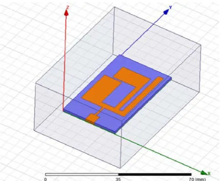
The geometry of the designed antenna is shown in the Figure 1.The antenna is made of a single patch on top, one layers of dielectric and a edge feed slot connected to the upper patch.
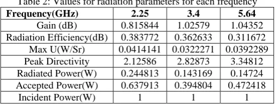
Table.1: Antenna specifications
Dimension W1 W2 W3 W4 h1 h2 h3 h4
Specification(mm) 17.5 10 23 32 25 07 14 05
IJEDR1503082
International Journal of Engineering Development and Research (www.ijedr.org)3
Figure 2: Design of Triple Band micro strip patch in HFSS software
III.RESULTS AND EXPLANATIONS
A. Return Losses
Figure 5 illustrates both the simulated and experimental results of the antenna return loss. Here, return loss is defined as
R =20log10 | Ґ| (5)
where Ґ is the reflection coefficient. As shown in this figure, simulated values of the first and second resonant frequencies are 2.31 GHz and 3.78 GHz, respectively. Current paths of the 1st and2nd modes are shown. Dash-dot lines show the average length of current paths for each mode. The resonant frequencies can be calculated approximately as follows:
𝑓𝑓1=2�ɛ𝑒𝑒𝑒𝑒𝑒𝑒𝑐𝑐 𝐿𝐿1 (6) 𝑓𝑓2=2�ɛ𝑐𝑐
𝑒𝑒𝑒𝑒𝑒𝑒𝐿𝐿2 (7)
𝑓𝑓3=2�ɛ𝑒𝑒𝑒𝑒𝑒𝑒𝑐𝑐 𝐿𝐿3 (8)
Where L1, L2 and L3 are the average lengths for current paths of the 1st and 2nd resonant modes and c is the free space velocity of light. The effective permittivity is also given by
ɛ𝑟𝑟𝑟𝑟𝑟𝑟 =ɛ𝑟𝑟+1
2 + ɛ𝑟𝑟−1
2 �1 + 10ℎ
𝑊𝑊� −0.555
(9)
Where h and W are height of the substrate and width of the patch. The return losses are shown in the below Figure 3.
Figure 3: Return losses
B. Radiation Pattern
The radiation field of the micro strip antenna may be determined using either an electric current model or a magnetic current model. In the electric current model, the current is used directly to find the far-field radiation pattern. The electric current for the (1,0) patch mode. If the substrate is neglected (replaced by air) for the calculation of the radiation pattern, the pattern may be found directly from image theory. If the substrate is accounted for, and is assumed infinite, the reciprocity method may be used to determine the far-field pattern. In the magnetic current model, the equivalence principle is used to replace the patch by a magnetic surface current that flows on the perimeter of the patch[9] [7].
IJEDR1503082
International Journal of Engineering Development and Research (www.ijedr.org)4
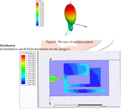
The radiation pattern is main concentration for the wide band application [12]. For wide band application the effect of the radiation up to 30 miles. The gain must be high for this type of application the radiation pattern isThe Figure 4 and 5 show the radiation pattern for the antenna at 5.64GHz. HPBW is the angular separation which the magnitude of the radiation pattern from the peak of the main beam decreases by 50% or -3 dB. HPBW (angle) is 70˚ for Optimum Frequency of 8.73 GHz.
Figure5: 3D-view of radiation pattern
D. Field Distribution
The E-field distribution and H-Field distribution for this design is
IJEDR1503082
International Journal of Engineering Development and Research (www.ijedr.org)5
Figure 7: H-field distribution for E-shape micro strip patch antennaFor the view of field distribution there is no uniform distribution in the single u-slot patch antenna. For non-uniform distribution of these fields the return losses are somewhat high. For decrease the return losses there must perfect matching between coaxial system and the radiating element then we can easily remove the return losses.
E. VSWR
Figure 8: VSWR for E-shape patch antenna
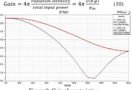
F. Gain
Another useful measure describing the performance of an antenna is the gain. Although the gain of the antenna is closely related to the directivity, it is a measure that takes into account the efficiency of the antenna as well as its directional capabilities. Remember that directivity is a measure that describes only the directional properties of the antenna, and it is therefore controlled only by the pattern. Gain of an antenna (in a given direction) is defined as “the ratio of the intensity, in a given direction, to the radiation intensity that would be obtained if the power accepted by the antenna were radiated isotropically [5] [7]. The radiation intensity corresponding to the isotropically radiated power is equal to the power accepted (input) by the antenna divided by 4π.” In equation form this can be expressed as
𝐺𝐺𝐺𝐺𝐺𝐺𝐺𝐺= 4𝜋𝜋𝑟𝑟𝑟𝑟𝑟𝑟𝑟𝑟𝑟𝑟𝑟𝑟𝑟𝑟𝑟𝑟𝑟𝑟𝑟𝑟𝑟𝑟𝑟𝑟𝑟𝑟𝑡𝑡𝑟𝑟𝑟𝑟𝑖𝑖𝑖𝑖𝑟𝑟𝑟𝑟𝑟𝑟𝑟𝑟𝑟𝑟𝑟𝑟𝑖𝑖𝑟𝑟𝑟𝑟𝑖𝑖𝑖𝑖𝑟𝑟𝑝𝑝𝑟𝑟𝑟𝑟 = 4𝜋𝜋𝑈𝑈(𝑖𝑖𝜃𝜃,𝜑𝜑)
𝑖𝑖𝑖𝑖 (10)
IJEDR1503082
International Journal of Engineering Development and Research (www.ijedr.org)6
best possible result. Substrate used was FR4epoxy which has a dielectric constant of 4.4. The results show the multiband antenna is able to operate with 2.25GHz, 3.4GHz and 5.64GHz frequencies. Due to the frequency of operation and compact area occupied, the proposed antenna is promising to be embedded within the different portable devices employing Wi-Fi, WiMAX and in different wireless applications.REFERENCES
[1] T. H. Kim, and D. C Park, “Compact Dual-Band Antenna with Double L-Slits for WLAN Operations,” IEEE Antennas and Wireless Propagation Letters, vol. 4, pp. 249-252, May 2005.
[2] C. Y. Pan, T. S. Horng, W. S. Chen, and C. H. Huang, “Dual Wideband Printed Monopole Antenna for WLAN/WiMAX Applications,” IEEE Antennas and Wireless Propagation Letters, Vol 6, pp. 149-151, Jan. 2007.
[3] L. Pazin, N. Telzhensky, and Y. Leviatan, “Multiband Flat-Plate
Inverted-F Antenna for Wi-Fi/WiMAX Operation,” IEEE Antennas and Wireless Propagation Letters, Vol. 7, pp. 197-200, Mar. 2008
[4] Zurcher, J. F., and F. E. Gardiol, Broadband Patch Antennas, Norwood, MA: Artech House, 1995.
[5] C.A. Balanis, “Antenna Theory: Analysis Design”, Third Edition, Chapter 14 - Microstrip Antennas, ISBN 0-471-66782-X Copyright © 2005 Jhon Wiley & Sons, Inc.
[6] I. J. Bhal and P. Bhartia, Microstrip Antennas, Artech House, Dedham, MA, 1980.
[7] James, J. R., and P. S. Hall, Handbook of Microstrip Antennas, Vol. 1, London: Peter Peregrinus Ltd., 1989.
[8] Derneryd, A. G. and A. G. Lind, ‘‘Extended Analysis of Rectangular Microstrip Resonator Antennas,’’ IEEE Trans. Antennas Propagation, Vol. AP–27, November 1979, pp. 846–849
[9] James, J. R., P. S. Hall, and C. Wood, Microstrip Antenna Theory and Design, London: Peter Peregrinus, 1981. [10] Girish Kumar, K. P. Ray, “Broadband Microstrip Antenna,” Artech House, Boston, London, 2003, pp. 38.
[11] M. T. Islam,M. Moniruzzaman, N. Misran, and M. N. Shakib, ‘Curve fitting based particle swarm optimization for UWB patch antenna’,
Journal of Electromagnetic Waves and Applications, vol. 23, no. 17– 18, pp. 2421–2432, 2009.
[12] M. Habib Ullah, M. T. Islam, J. S. Mandeep, “Printed Prototype of A Wideband S Shape Microstrip Patch Antenna for Ku/K Band Applications”, Applied Computational Electromagnetics Society Journal, 28(4), 307-310, 2012.
[13] M. T. Islam, M. Habib Ullah, “Analysis of A Dual Resonant Multiple Split Ring Patch Antenna”, International Journal of Circuit Theory and Applications, 2013.
[14] R. Azim, M. T. Islam, N. Misran, S. W. Cheung, and Y. Yamada, ‘Planar UWB antenna with multi-slotted ground plane’, Microwave and Optical Technology Letters, vol. 53, no. 5, pp. 966–968, 2011.