A Proposal for the Upgrade of the Muon Drift Tubes Trigger for
the CMS Experiment at the HL-LHC
NicolaPozzobon1,2,a, PierluigiZotto1,2, and FabioMontecassiano2
1Università degli Studi di Padova, Italy
2INFN Sezione di Padova, Italy
Abstract.A major upgrade of the readout and trigger electronics of the CMS Drift Tubes muon detector is foreseen in order to allow its efficient operation at the High Luminosity LHC. A proposal for a new L1 Trigger Primitives Generator for this detector is presented, featuring an algorithm operating on the time of charge collection measurements provided by the asynchronous readout of the new TDC system being developed. The algorithm is being designed around the implementation in state-of-the-art FPGA devices of the original development of a Compact Hough Transform (CHT) algorithm combined with a Majority Mean-Timer, to identify both the parent bunch crossing and the muon track parameters. The current state of the design is presented along with the performance requirements, focusing on the future developments.
1 Introduction
Muon identification at the CMS experiment relies on a redundant detection system exploiting three different technologies: Drift Tube chambers (DT) in the central region |η| < 1.2, Cathode Strip Chambers (CSC) in the forward region|η|>1.1 and Resistive Plates Chamber (RPC) in both regions [1]. Signals from all these sub-systems are used to build the Level 1 Trigger (L1) decision for the on-line identification of muon tracks. However, the currently available on-on-line momentum resolution does not allow to retain manageable trigger rates after the High Luminosity LHC upgrade is completed [2]. Several upgrades of the muon electronics are under design, including the replacement of the current DT readout and L1 local trigger. The current L1 DT local trigger electronics was produced in the early 2000 and is hosted on-detector, therefore it is old and suffering from radiation damage. Hence a project aiming to the full replacement of the readout and trigger electronics was started. Given the limited amount of information to be moved, the current design of the new readout foresees an asynchronous data feed via high speed optical link of all collected signals, straight from the detector, without any intermediate decision stage. The DT local Trigger Primitive Generator (TPG) will then need to operate on time-stamped data stored in large memories off-detector. This approach is not compatible with the current DT TPG [3], which is based on a synchronous track segment reconstruction designed around a time-dependent fitter for the parent bunch crossing identification. Therefore, a new, modern, fast and efficient trigger scheme needs to be developed.
honeycomb plate iron yoke
SL 3 /
SL 2 /
SL 1 /
x z
φ
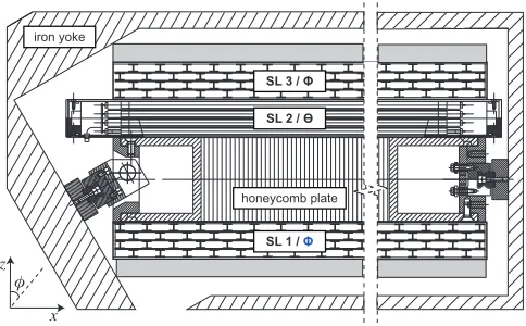
Figure 1.Layout of a CMS DT chamber. Wires are arranged in layers, and parallel layers are grouped four-by-four into super-layers. Each chamber features two super-layers in therφprojection and one super-layer in theθ projection. Each drift cell is 4.2 cm wide and 1.3 cm high, while the distancedbetween the centre of the tworφ
super-layers is 23.5 cm. Theθsuper-layer is not used in this preliminary study.
2 Requirements
The 240 CMS DT chambers, interleaved with the CMS solenoid return iron yoke, can be described as telescopes of position-sensitive detectors, grouped together in parallel layers, as shown in Figure1. Each chamber provides an array of charge collection timestimeasured from a common starting signal,
called BC0, distributed by the machine and corresponding to the first bunch crossing in an LHC cycle. These times are converted into drift time measurementsTi, once the parent bunch crossing timetpwith
respect to BC0 is identified.
The new trigger scheme must use the drift-times in order to identify approximately straight track segments1with an efficiency and a resolution comparable to the ones of the current trigger system: the required efficiency must be higher than 98% over a range spanning approximately±50◦ in the local angleφ, the angular resolution must be better than 30 mrad (3 mrad) using measurements from 4 (8) wires, and the resolution on track intercept must be better than 1.4 mm.2
Each drift timeTi is converted into a drift distance to the anode wire, but each reconstructed
muon hit in any drift time chamber comes accompanied by a second position measurement due to the unresolved left-right ambiguity. Therefore, the track segment reconstruction must deal with an amount of spurious position measurements of the same order of the actual crossing coordinates of the muon in addition to the noise contribution. The trigger must then provide robust identification of the muon within a non negligible amount of background with onlyO(10) measurements and limiting the amount of ghost tracks in order to keep rates at a manageable level, within fewμs latency.
The proposed approach is split in two parts: the determination of the parent bunch crossing time
tpby means of a mean-timing technique and the evaluation of the muon track parameters by means
of a fast and dedicated implementation of the Hough transform (HT). We will first discuss the HT
implementation assumingtpis exactly known, and afterwards introduce thetpcomputation method in
order to decouple algorithmic effects.
3 Hough transform for the DT TPG
The Hough transform [6–8] is a well-established pattern recognition technique worth being investi-gated for a new DT TPG, given its robustness and simplicity, but whose implementation requires a lot of computing resources. We performed a first evaluation study to identify and tailor a HT implemen-tation scheme that can match the efficiency and resolution requirements listed in Section2and which could be suitable for implementation in programmable logic devices. We have shown that a param-eter reduction, combined with a clever partitioning of the input dataset and dimensioning of the HT histograms, brings the size of HT histograms and the complexity of the computations compatible with the typical specifications of state-of-the-art FPGA devices [5]3. In this contribution we report only
on the status of our studies for the identification of track segments in therφprojection, therefore we refer to measurements of super-layers 1 (inner) and 3 (outer) according to the convention of Figure1. The layout of the CMS DT chambers intrinsically accounts for non-degenerate slope-intercept description using the reference system shown in Figure1. A straight track is therefore described by the equation:
x=−m·z+c,
where the local track angleφ =tan−1mis measured with respect to the orthogonal direction ˆz. For
each recorded time, the position of the layer defines thezcoordinate andxis the transverse coordinate reconstructed from the drift time. In the HT parameter space, each (x,z) measurement is transformed into a line of slopezand interceptx:
c=z·m+x. (1)
These lines fill the bins of a two-dimensional histogram in the (m,c) parameter space and intersect when the same parameters are found for different (x,z) points, thus originating an accumulation in the parameter space. The best parameters values are identified as the position within the parameter space where the majority of contributions is gathering.
The actual algorithm implementation features three independent HT histograms which are filled in parallel: one for super-layer 1, one for super-layer 3, and one combining both of them together. The histograms are then compared to each other in order to define the best values of muon track parameters. The DT drift cells in each super-layer are grouped into macro-cells spanning approximately 16 cm in
x, to reduce the number of input hits to be considered simultaneously for track identification, and partially overlapped, to ensure optimal redundancy and hermeticity for track finding up to|φ| ≈50◦. The coordinatezof each measured point becomes the slope of the corresponding line in the param-eter space. Such transformed lines can become degenerate with large values ofz, i.e. almost vertical and separated by very small angles. This can affect the identification of the peak in the parameter space, which is better identified by lines crossing each other with large and evenly distributed angles. This condition corresponds to having measurements evenly distributed aroundz= 0. Hence, when using only one super-layer, we setz=0 between its central layers, while in case both super-layers are used, we setz=0 on the median plane of the chamber.
Therefore, for a given track, the input measurements are naturally split into three different subsets, allowing to identify the track by means of three different HT histograms (aninner HTfor super-layer 1; anouter HTfor super-layer 3; achamber HT for both super-layers) that are recombined with each other after histogram filling completion. Histograms are recombined on a track-slope basis, being this
] ° [ φ local 60
− −40 −20 0 20 40 60
efficiency 0.0 0.2 0.4 0.6 0.8 1.0 1.2 4/4 6/8 ≥ integer CHT resid. [mrad] φ local 20
− −10 0 10 20
max N/N 0.0 0.2 0.4 0.6 0.8 1.0 1.2 4/4 6/8 8/8
integer CHT σ [mrad] = 10.55 ---2.13
°
| < 15
φ local | resid. [mm] 0 x local 6
− −4 −2 0 2 4 6
max N/N 0.0 0.2 0.4 0.6 0.8 1.0 1.2 4/4 6/8 8/8
integer CHT σ [mm] = 1.29 ---0.26
°
| < 15
φ
local |
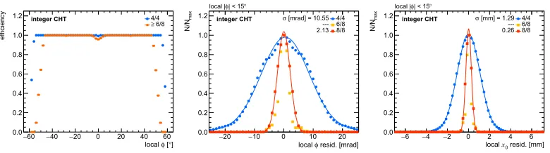
Figure 2. CHT algorithm efficiency for finding track segments with 4 aligned reconstructed hits in one super-layer (4/4) and for at least 6 aligned reconstructed hits in both super-layers (6/8), shown as a function of the local track angleφ(left). Resolution of the reconstructed local track angleφ(centre) and intercept x0 (right)
with 4 aligned reconstructed hits in one super-layer (4/4), with 6 aligned reconstructed hits in both super-layers (6/8), and with 8 aligned reconstructed hits in both super-layers (8/8), for tracks with local angle|φ| <15◦. The resolution is expressed as the square root of the variance of a weighted sum of two normal functions used to fit the distribution of the residuals. The muon crossing timetpis assumed to be exactly known at this stage, to
decouple the bunch crossing identification effects.
parameter non sensitive to the choice ofz =0. In a Standard HT (SHT) approach, this means that histograms are projected onto them- axis after a pre-defined threshold on the number of entries is applied to the parameter space bins. Different thresholds are used to assign a quality to the candidate track segment, the quality being higher for higher counts. Such projected histograms producem -bitsets, which are then combined together with a bitwise ‘AND’ operation in order to identify the smallest subset of slope values common to all the three subsets. The bestmvalue is then obtained by means of a simple clustering algorithm.
The track interceptcinn,out is recalculated for each single super-layer subset and afterwards
con-verted to the valuex0in the chamber reference frame. If both super-layers are available, the estimate
ofmcan be improved exploiting the large lever arm:
x0=cinn+cout
2 ,
m=cinn−cout
d .
If, on the contrary, only one super-layer returns a positive result,mis unchanged from the low reso-lutionm-bitset estimate, andx0is the extrapolation of the local intercept to the middle plane of the
chamber.
A Compact HT (CHT) approach was developed in order to reduce the number of parameters. The parameter reduction exploits the fact that each pair of aligned hits must return the same values form
andc. Given that onlymis used in the histogram recombination scheme, one can consider pairs of measurements and combine Equation (1) for two different measurements into
Δc= Δz·m+ Δx,
toΔc=0 is relevant for the determination of hit alignment. This allows to handle one-dimensional histograms, i.e. only theΔc ≈0 row of a two-dimensional (m,Δc) histogram. Defining the size of the bins and the best thresholds requires an accurate tuning of the available options. The best working points identified in our study indicate a size reduction of the HT histogram area, comparing the SHT and the CHT approach, by a factor≈35. The benefit on the histogram size of moving from the use of single hits of a SHT to couples of hits has the drawback of a more complicated handling of input hits. Efficiency and resolution for different qualities were evaluated with a fully-integer representation of the algorithm and are shown in Figure2, assuming the muon crossing time is exactly known. A first Register Transfer Language (RTL) high-level synthesis of the CHT algorithm has been performed showing that it can be implemented in a state-of-the-art FPGA, although the timing performance is still far from requirements. Variants of the method improving the latency are being studied.
4 Bunch crossing identification
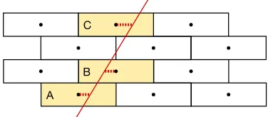
The current bunch crossing (BX) identification scheme is based on a time-dependent synchronous fitter (the BTI ASIC [9]), sampling different BX hypotheses with 12.5 ns precision. Since this scheme cannot work with the foreseen asynchronous data feed, we propose another way to exploit the mean-timing, which is one of the key features of the CMS DT chambers design since RD5 [10]. Any meaningful triplet of wires (labeled ‘A’, ‘B’, and ‘C’), in different layers within a super-layer and assuming a left-right hypothesis in each tube, is associated to a linear combinationLof the drift times
TA,TB,TCand the maximum drift time in a tubeTmax:
L(Tmax,TA,TB,TC)=0, (2)
where all coefficients inLare integer.4 One such example is presented in Figure3. The very same
linear combination can be made explicit in terms of the particle crossing timetp, inverting the relation
between the drift timeTiand the time to charge collection timesti
L(Tmax,tA,tB,tC)−SABC·tp=0, (3)
being the coefficients of the linear combinationLidentical in (2) and (3) for corresponding patterns, andSABCthe algebraic sum of the coefficients multiplyingTA,TB,TC in (2). The majority of the
meaningful patterns hasSABC0, making it straightforward to computetpat once for those patterns.
All meaningful patterns in a macro-cell are used to computetp by means of tables and counts,
without the need oftpsampling as done in the BTI. The most votedtpis chosen and used to convert
each measuredti into a pair of reconstructed positionsxi,leftandxi,right. If thetp computed from the
inner super-layer macro-cell is different from the one computed in the outer super-layer macro-cell, both hypotheses are tested: typically, only the good one returns a valid track, since the CHT histogram built from both super-layers naturally suppresses ghost track segments. The procedure can be then defined as a static Majority Mean-Timer (MMT). The performance of the MMT+CHT chain has been evaluated with a fully-integer representation of both algorithms, assigning each track a random BX over one LHC orbit, and the relevant figures of merit are shown in Figure4, without any check on the MMT result, and in Figure5, where only in-time muon candidates are plotted. A comparison between the two Figures shows that the evaluation technique does not introduce any resolution degradation, while introducing some out-of-time and therefore wrong triggers. Figure5shows also that the mean-timer is not working beyond|φ| ≈50◦where the contribution of single super-layers is crucial, while all in-time evaluations provide excellent resolution. The fraction of wrongtpidentifications at angles
|φ|<40◦is of the order of 10−4.
Figure 3.Example of a Mean-Timer equation for one particular triplet of wires and left-right crossing hypothesis (A is right, B is left and C is right), leading toL(Tmax,TA,TB,TC) =2TA+3TB+TC−2Tmax =0 andtp =
(2tA+tB+tC−2Tmax)/6.
] ° [ φ local 60
− −40 −20 0 20 40 60
efficiency 0.0 0.2 0.4 0.6 0.8 1.0 1.2 4/4 6/8 ≥ integer MMT+CHT resid. [mrad] φ local 20
− −10 0 10 20
max N/N 0.0 0.2 0.4 0.6 0.8 1.0 1.2 4/4 6/8 8/8
integer MMT+CHT σ [mrad] = 10.53 ---2.14
°
| < 15
φ local | resid. [mm] 0 x local 6
− −4 −2 0 2 4 6
max N/N 0.0 0.2 0.4 0.6 0.8 1.0 1.2 4/4 6/8 8/8
integer MMT+CHT σ [mm] = 1.29 ---0.26
°
| < 15
φ
local |
Figure 4.MMT+CHT algorithm efficiency for finding track segments with 4 aligned reconstructed hits in one super-layer (4/4) and with at least 6 aligned reconstructed hits in both super-layers (6/8), shown as a function of the local track angleφ(left). Resolution of the reconstructed local track angleφ(centre) and interceptx0(right)
with 4 aligned reconstructed hits in one super-layer (4/4), with 6 aligned reconstructed hits in both super-layers (6/8), and with 8 aligned reconstructed hits in both super-layers (8/8), for tracks with local angle|φ|<15◦. The resolution is expressed as the square root of the variance of a weighted sum of two normal functions used to fit the distribution of rhe residuals. Inclusive results are shown.
] ° [ φ local 60
− −40 −20 0 20 40 60
efficiency 0.0 0.2 0.4 0.6 0.8 1.0 1.2 4/4 6/8 ≥
int. MMT+CHT, in-time
resid. [mrad] φ local 20
− −10 0 10 20
max N/N 0.0 0.2 0.4 0.6 0.8 1.0 1.2 4/4 6/8 8/8
int. MMT+CHT, in-timeσ [mrad] = 10.65 ---2.14
°
| < 15
φ local | resid. [mm] 0 x local 6
− −4 −2 0 2 4 6
max N/N 0.0 0.2 0.4 0.6 0.8 1.0 1.2 4/4 6/8 8/8
int. MMT+CHT, in-time σ [mm] = 1.34 ---0.26
°
| < 15
φ
local |
5 Future perspective and concluding remarks
The design of a HT-based algorithm to be implemented in FPGA targeting the replacement of the CMS DT TPG upgrade for the HL-LHC is currently ongoing and promising. An extensive study of the main parameters of the algorithm has been completed and the resulting fully-integer simulation matches the performance of the floating point one. The BX identification based on Mean-Timer techniques is providing correct results, and there is still some margin for improvements. Also, the BX identification does not add any degradation in terms of resolution. This study will benefit from the evaluation of the results of the first RTL synthesis which will hint to bottlenecks and will suggest improvements. Other valuable input could be available from the inclusion of real-life effects as well as from running the algorithm on CMS collision data.
References
[1] The CMS Collaboration, JINST3, S08004 (2008) [2] N. Pozzobon et al., Nucl. Inst. & Meth. A824, 346 (2016) [3] P. Arce et al., Nucl. Inst. & Meth. A534, 441 (2004) [4] S. Betkhe et al., Nucl. Inst. & Meth. A416, 243 (1998)
[5] N. Pozzobon, F. Montecassiano, P. Zotto, Nucl. Inst. & Meth. A834, 81 (2016) [6] P.V.C. Hough, U.S. patent3,069,654(1962)
[7] J. Illingworth, J. Kittler, Comp. Vis. Graph. Image Proc.44, 87 (1988) [8] P. Mukhopadhyay, B.B. Chaudhuri, Pattern Recognition48, 993 (2015) [9] M.D. Giorgi et al., Nucl. Inst. & Meth. A438, 302 (1999)