Simulation and Dynamic Performance
analysis of HVDC Power Transmission Using
Wind Power Generation
Jeswin Ouseph 1, Dr. Jyoti shrivastava2
PG Student, Department of Electrical Engineering, SHIATS-DU Naini, Allahabad, India1
Assistant Professor, Department of Electrical Engineering, SHIATS-Deemed University, Allahabad India.2
ABSTRACT:This paper proposes a simulink model of wind turbine using induction generator and performance analysis of high voltage direct current power converter station. This paper also shows how wind power can easily be generated with help of induction generator. The need of developing such a system promoted the utilization of non-conventional energy resources like wind power. For a developing country like India the electrical energy much mire required to achieve the estimated targets within the specified period of time. Since the power generation is not only our concern but also power transmission have great importance to transport the electrical energy over long distance easily and efficienctly, which ensures uninterrupted and regulated power supply at load end. Hence this paper also proposes a model to transmit electrical power in DC form. Since it is difficult to load long extra high voltage (EHV) ac lines to their thermal limits as a sufficient margin is kept against transient instability. With the model proposed in this thesis, it will be possible to load these lines close to their thermal limits. The transmission lines are allowed to carry usual ac along with dc superimposed on it.
KEYWORDS—HVDC,HVAC, Wind Turbine, Energy, Integrated System, Flexible AC Transmission System (FACTS) .
I.INTRODUCTION
In recent years, environmental, right-of-way (Row), and economic concerns have delayed the construction of a new transmission line. The demand of electric power has shown steady growth but geographically it is quite uneven. The power is often not available at the growing load centers but at remote locations. Often the regulatory policies, environmental acceptability, and the economic concerns involving the availability of energy are the factors determining these locations. Now due to stability considerations, the transmission of the available energy through the existing ac lines has an upper limit. Thus, it is difficult to load long extra high voltage (EHV) ac lines to their thermal limits as a sufficient margin is kept against transient instability. The present situation demands for the fact that there is full utilization of available energy applying the new concepts to the traditional power transmission theory keeping in view the system availability and security. The flexible ac transmission system (FACTS) concepts is based on the application of power electronic technology to the existing ac transmission system, this improves stability to achieve power transmission close to its thermal limit. Simultaneous ac–dc power transmission was earlier proposed through a single circuit ac transmission line i.e. uni-polar dc link with ground as return path was used. The limitations of ground as return path is due to the fact that the use of ground may corrode any metallic material if it comes in its path. The instantaneous value of each conductor voltage with respect to ground becomes higher due to addition of dc voltage; hence more discs have to be added in each Insulator string so that it can withstand this increased voltage. The conductor separation distance was kept constant, as the line-to-line voltage remains unchanged. This thesis gives us the feasibility of converting a double circuit ac line into composite ac–dc power transmission line without altering the original line conductors, insulator strings and tower structures.
Another way to achieve the same goal is by the application of simultaneous ac–dc power transmission to the traditional power system in which the transmission lines carry superimposed dc current along with ac current. Addition of the dc power does not cause any instability and both ac and dc power flows independently.
Earlier it was proposed through a single circuit ac transmission line i.e. uni-polar dc link with ground as return path was used. The limitations of ground as return path is due to the fact that the use of ground may corrode any metallic material if it comes in its path. The instantaneous value of each conductor voltage with respect to ground becomes higher due to addition of dc voltage, hence more discs have to be added in each insulator string so that it can withstand this increased voltage. The conductor separation distance was kept constant, as the line-to-line voltage remains unchanged. This thesis gives us the feasibility of converting a double circuit ac line into composite ac–dc power transmission line without altering the original line conductors, insulator strings and tower structures.
Our approach is based on the fact that the power transfer enhancement is achieved without any alteration in the existing Extra High Voltage ac line. The objective is to utilize the advantage of parallel ac–dc transmission by loading the line close to its upper thermallimit.
The figure below shows cost and distance curve between HVAC and HVDC system.
Fig. 1. Cost of HVDC and HVAC systems for offshore connection
Problems associated with HVAC systems are as follows:
(a) The Current Density increases due to the increase in line loading by series capacitors. (b) Higher surface voltage gradient on conductors hence skin effect.
(c) Corona problems: Audible Noise, Radio Interference, Corona Energy Loss, and TV Interference.
(d) Electrostatic field under the line is high.
(e) Switching Surge Over voltage causes more difficulty in insulation than lightning and power frequency voltages.
(f) Increased Short-Circuit currents.
II.THEORY OF SIMULTANEOUS AC-DCTRANSMISSION
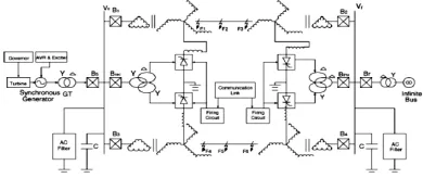
Fig. 2 depicts the basic model for simultaneous ac-dc power flow through a dual circuit ac transmission line. Line commutated 12-pulse rectifier bridge is used in conventional HVDC and the dc power is injected to the neutral point of the zig-zag connected secondary of sending end transformer and is recovered back to ac again by the line commutated 12-pulse bridge inverter at the receiving end side. The inverter bridge is also connected to the neutral of zig-zag connected winding of the receiving end transformer to recover back the dc current to the inverter.
The dual circuit ac transmission line carriers both three-phase ac and dc power. Each conductor of each transmission line carries one third of the total dc current with ac current superimposed. Since the resistance is equal in all the three phases of secondary winding of zig-zag transformer and the three conductors of the line, the dc current is equally divided in all the three phases. The conductor of the second transmission line provides return path for the dc current to flow. The saturation of transformer due to dc current can be removed by using zig-zag connected winding at both ends. The fluxes produced by the dc current (Id / 3) flowing through each winding of the core of a zig-zag transformer have equal magnitude and opposite in direction and hence cancel each other. At any instant of time the net dc flux becomes zero. Thus, the dc saturation of the core is removed. A reactor Xd with higher value is used to reduce harmonics in dc current. In the absence of third order harmonics or its multiple and zero sequence, under normal operating conditions, the ac current flow through each transmission line gets restricted between the zig-zag connected windings and the conductors of the transmission line. The presence of these components may only be able to produce negligible current through the ground due to higher value of Xd
.
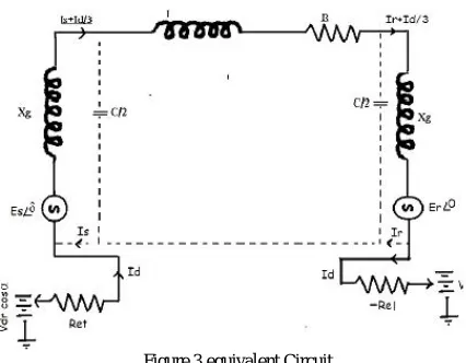
Assuming constant current control of rectifier and constant extinction angle control of inverter,the equivalent circuit of the model considering single ac line under steady-state operating condition is given in Fig. 3.Figure.3 equivalent Circuit
The ac current return path is denoted by brisk lines in the figure. The second transmission line acts as the return path for dc current, and each conductor of the line carries (Id /3) along with the ac current per phase and the maximum values of rectifier and inverter side dc voltages are Vdro and Vdio respectively. The line parameters per phase of each line R, L and C. Rcr and Rci are thecommutating resistances, and, _ is the firing angle and _ is the extinction angles of rectifier and inverter.
The chief methodology of solving the equations is by neglecting the resistive drops because of dc currents giving a set of algebraic expressions for ac voltage and current, and also for active and reactive powers in terms of A, B, C, D parameters of each line. These may be written as:
Es = AER + BIR--- (1)
Is = CER + DIR ---(2)
Ps + jQs = -Es*ER*/B* + D*ES2/B*--- (3)
If we neglect the resistive drops in the zigzag transformers and the tie lines, the dc current Id, dc power Pdr and Pdi of
each rectifier and inverter may be expressed as:
Id=[Vdro Cosα - Vdio Cos γ ]/[ Rcr +Req - Rci ] ---(5)
Pdr = Vdr*Id --- (6)
Pdi = Vdi*Id --- (7)
Reactive powers needed by the converters are: Qdr = Pdr *tanθr --- (8)
Qdi = Pdi *tanθi --- (9)
cosθr = [cosα + cos( α+ μr)]/2 ---(10)
cosθi = [cosγ + cos(γ+ μi)]/2 ---(11)
μiis the commutation angles of inverter and μr is the commutation angle of rectifier and the overall active and reactive powers at both the ends are: Pst = Ps + Pdr and Prt = PR + Pdi ---(12)
Qst = Qs + Qdr and Qrt = QR + Qdi --- (13)
Transmission loss for each line is: PL = (PS + Pdr) – (PR + Pdi) ---(14)
Ia is the rms ac current through the conductor at any part of the line, the rms current per conductor of the line becomes: I = [Ia2 + (Id/3)2]1/2; Power loss for each line = PL = 3I2R. The total current I in any of the conductors is offset from zero. Now by setting the net current through the conductor similar to its thermal limit(Ith): Ith = [Ia2 + (Id/3)2]1/2 ---(15)
Let Vp be per phase rms voltage of the initial ac line. Also Let us consider Va be the per phase voltage of the ac part of simultaneous ac-dc tie line with constant dc voltage Vd composed on it.As the insulators are unchanged, the peak voltage in the two cases must be equal. If the rated conductor current with respect to its allowable temperature increase is Ith and Ia = X * Ith; X ( too less than unity) hence the dc current becomes: Id = 3 x (sqrt (1-x2) ) Ith ---(16)
The total current I in all the conductors are` asymmetrical but the two original zero-crossings in each one cycle in current wave are possessed for (Id/3Ia) <1.414.
The instantaneous value of voltage of each conductor that is phase to ground voltage can be written as the dc voltage Vd with a composition of sinusoidally varying ac voltages that has rms value Eph and the peak value being:
Emax = V + 1.414 Eph
Electric field of the composite AC-DC line also consists of the field produced by the dc line feeding power and also the ac line creating a superimposed effect of electric fields. It can be
easily seen that the sudden changes in electric field polarity occurs and it changes its sign twice in a single cycle if (Vd/Eph) < 1.414. Therefore, we are free from incurring higher creepage distance for insulator discs used in HVDC lines .
Each conductor has to be insulated for the maximum Emax but the fact is line to line voltage has no component of dc
voltages and ELL(max) = 2.45 Eph. Therefore, we come to the conclusion that conductor to conductor separated distance is found out only by ac voltage of the line in lieu of the total superimposed one.
Pdc/Pac = (Vd * Id)/(3 * Eph * Ia * cos_)
= (k * sqrt(1-x2))/(x * cosθ ) ---(17) Total power
Pt = Pdc + Pac = (1 + [k * sqrt (1-x2)]/(x * cosθ)) * Pac ---8)
Detailed analysis of the filter and instrumentation networking which are required for the proposed scheme and also short current ac design for protective scheme is out the scope of present work, but preliminary analysis qualitatively presented below says that generally used techniques in HVDC/ac composite system can be adopted solely for this purpose. Different values of ac filters and dc filters are used in HVDC system and these may be connected to the delta side of the transformer and zigzag neutral respectively to filter out higher harmonics.
that is (n*p+1)th order and the (n*p)th order from dc and ac supplies. Moreover ,filters also may be omitted for very low values of Vd and Id. In the neutral terminals of zigzag transformer winding dc current and dc voltages can be found out by incorporating common methods that are used in HVDC system. Conventional or capacitive voltage transformer as used in EHV ac lines to measure stepped down ac component of transmission line voltage. The composite ac-dc voltage in the transmission line does not trouble the working of cvts. Linear couplers that has high air-gap core may be used for measuring ac component of line current as the dc component of line current cannot saturate high air-gap cores.
III. RESULT
The fallowing simulation results show the successful transmission of HVDC power transmission using wing power generation. Vdc represents DC power transmitted between two converter stations. The integrated power systems sending
end voltage first converted into DC with the help of universal bridge and then it is inverted into high voltage AC with the help of three phase inverter which in a IGBT. With the help of IGBT triggering of circuit commutation can be controlled and hence power transmission can also be controlled easily.
In above figure 4 output of three phase inverter and filtered ac power transmitted to load is shown along with modulation index.
Fig.5 FFT analysis
Fig.6 THD analysis
fig.5 and fig.6 represents the total harmonic distortion of selected signal, which is in this case three phase ac power at load i.e. Vload .The THD is this proposed model at the load end is 3.99% ,which reprents suceesful and efficient
transmission of power of a system containing conventional AC power generation and wind generation.
IV.CONCLUSION
Today HVDC is very important issue in transmission energy. In near future this technology probably will be developing very intensive. Influence on future may have intensive spread of renewable energy source, also wind farm which need undersea connections. Also problem of cascade blackout, can be reduced by application of HVDC. Intensive, very large investments in e.g in China and India shows that high-voltage direct current will very important in the future, especially in big, new-industries countries
.
SPUE: In this attack, an attacker’s objective is to maximize its own spectrum usage. When selfish attackers detect a
REFERENCES
[1] H. Rahman, “Upgradation of Existing EHVAC Line by Composite AC-DC Transmission”, International Conference on Communication, Computer and Power (ICCCP'09), MUSCAT, February 15-18, 2009.
[2] H. Rahman and B. H. Khan, Senior Member, IEEE, “Power Upgrading of Transmission Line by Combining AC–DC Transmission”, IEEE Transactions on Power Systems, Vol.
22, No. 1, February 2007.
[3] T. Vijay Muni, T. Vinoditha and D. Kumar Swamy, “Improvement of Power System Stability by Simultaneous AC-DC Power Transmission” International Journal of Scientific & Engineering Research Volume 2, Issue 4, April-2011.
[4] Prabha Kundur-power system stability and control Tata Mcgraw Hill edition, New Delhi 1993, 11th reprint 2011.
[5] N. G. Hingorani, “FACTS—flexible A.C. transmission system,” in Proc. Inst. Elect. Eng. 5th. Int. Conf. A.C. D.C. Power Transmission. [6] Padiyar.’HVDC Power Transmission System.’ New Age International Publishers, New
Delhi, 2nd revised edition 2012.
[7] I W Kimbark.’Direct Current Transmission Vol-I.’Wiley, New York, 1971.
[8] Clerici A., Paris L. and Danfors P. “HVDC conversion of HVAC Line to Provide Substantial Power Upgrading”, IEEE transactions on Power Delivery, vo1.1,1991 pp:324-333.