A Wideband Medium-Gain Vertically Polarized Omnidirectional
Antenna Array
Long Yang*
Abstract—A medium-gain vertically polarized omnidirectional antenna array (VPOA) with wide
bandwidth is proposed in this paper. Initially, a conventional printed dipole antenna with integrated balun (IB) is introduced to use as the wideband element. Then, four antenna elements are alternately arranged in the vertical direction to achieve high gain. Moreover, the four elements are excited by a shunt-fed feeding network which is utilized to provide uniform amplitude and phase for the elements. The feeding network has a common ground with the balun, and it can be easily integrated with the IB. Furthermore, two metallic cylinders placed in the normal direction of the substrate are used as two reflectors to improve the gain variation in the horizontal plane. In order to validate the design method, a prototype is fabricated and measured. The measured results indicate that the proposed antenna has an impedance bandwidth of 56% (1.12–2 GHz) for VSWR2 and a simple structure with lateral size of 0.45λ0 (λ0 is the free-space wavelength at center frequency). In addition, stable omnidirectional radiation patterns are obtained with gains around 6.5 dB and the gain variations in the horizontal plane less than 2 dB across the operating band.
1. INTRODUCTION
Vertically polarized omnidirectional antennas with high performance are paid more and more attention with the rapid development of modern wireless communications [1–4]. A vertically polarized omnidirectional antenna with the advantages of wide band, high gain, stable omnidirectional radiation pattern and being feasible and convenient to integrate with the feeding network is more likely widely adopted in a variety of services.
In the last few years, a great many VPOAs have been proposed. However, most of them can hardly guarantee to meet all the requirements mentioned above. Typically, vertical dipoles and monopoles are the most common vertically polarized omnidirectional antennas [5, 6]. However, their narrow bandwidths and limited gains are still challenges for future applications. By transposing the outer and inner conductors in a long coaxial cable, coaxial collinear antennas have gains more than 10 dBi [7, 8], but they suffer from narrow impedance bandwidths (less than 10%). Later, an omnidirectional planar microstrip antenna [9] and an omnidirectional planar slot antenna [10] are proposed, and they are composed of a series of sections of microstrip antenna alternately arranged at each junction and a series of rectangular-shaped loop slots etched on two parallel strip lines, respectively. Though they can achieve high gain above 6 dBi, their 10-dB impedance bandwidths are both less than 10%, and their beam directions are sensitive to the operation frequency, resulting in unstable radiation patterns. By using back-to-back printed dipole elements, the planar VPOA in [11] was convenient to be arrayed for a higher gain and obtained a bandwidth of 5.5%. In order to improve the impedance bandwidth of the VPOA antenna with back-to-back printed elements, a few effective approaches have been investigated [13–17]. By using a printed dipole with an integrated balun [12], the antenna array with 8 elements in [13]
Received 28 July 2018, Accepted 25 September 2018, Scheduled 16 October 2018 * Corresponding author: Long Yang ([email protected]).
170 Yang
achieves a bandwidth of more than 40% with a high gain. However, its omnidirectionality is not good due to its unidirectional radiation pattern. Based on a coupling feed structure, the printed dipole antenna in [14] achieves an operating bandwidth about 45.6%. In [15], unsymmetrical dipole elements and parasitic strips were employed to generate dual bandwidths of 20.2% and 21.3% for 2.6 GHz and 3.5 GHz bands, respectively. And its gains in the two operating bands are above 6.5 dBi. In [16], a novel VPOA antenna installed with three units, each of which utilized 3-D dipoles and parasitic dipoles, vertically installed and each 120◦ rotated compared to the adjacent one, was introduced to yield the increased bandwidth about 56% for VSWR < 1.5 and a gain from 5.7 to 8.0 dBi. As reported in [17], a wideband omnidirectional antenna array with nonsymmetric U-strip stubs antennas is proposed. Its operating bandwidth could exceed 60% by using non-symmetric U-strip stubs antennas to excite additional resonant modes. However, all these three antennas in [14–17] unfortunately bring out bulky and complicated geometry at the cost of an enlarged lateral size. Other approaches for high gain concentrate in dual-band instead of broadband for covering ranges for mobile communications based on using microstrip patches and genetic algorithm optimization are proposed [18–20]. These antennas are able to cope simultaneously with two services at two different bands with high gain; however, their total bandwidths are still not wide enough for an application with 50% bandwidth.
In this letter, a wideband medium-gain VPOA using wideband printed dipole antenna elements is presented. Firstly, a conventional printed dipole antenna with integrated balun is explored to design the wideband array element. After that, the arrangement methods of the wideband elements to form a VPOA array with small gain variation in the horizontal plane are carefully investigated. Then, two metallic cylinders placed in the normal direction of the substrate, aiming to further improve the omnidirectional radiation performance. In addition, a shunt-fed network is designed to guarantee stable pattern that has a common ground with the wideband antenna, which can easily integrated with the balun and the radiators. Finally, the proposed VPOA is fabricated and tested. Details of the proposed printed dipole-array antenna are described, and experimental results of a prototype are presented. It is verified in experiment that the impedance bandwidth (VSWR2) of the antenna is 56%. Moreover, the developed design has a stable gain about 6.5 dB and small gain variation less than 2 dB across the band with small lateral size of 0.45λ0. The array may find applications in many wideband omnidirectional communication systems due to its advantages.
2. ANTENNA DESIGN AND DISCUSSION
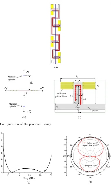
Figure 1 shows the configuration of the proposed antenna. It consists of four wideband printed dipole antenna elements with IB, as shown in Fig. 1(a), a one-to-four shunt-fed network and two metallic cylinders, as shown in Fig. 1(b). The dipole antenna element is printed on a 1 mm-thick substrate (εr= 2.65, tanδ = 0.002), with a width of 35 mm. The shunt-fed network to feed the antenna element is printed on the same side of the substrate with the IB, which is advantageous to the integration. Two metallic cylinders are used as reflectors to achieve an ideal omnidirectional pattern. The design procedure of the antenna array and the acquirement of the parameters will be presented in the following content.
2.1. Design of Wideband Antenna Element
In order to achieve wideband property for the antenna array, the design of wideband antenna element cannot be more important. Thus a wideband antenna element is first explored.
(a)
(b) (c)
Z
Y
+Y
X Y
d3
-Y
+X -X Metallic
cylinder
Metallic cylinder
wa
wb
za
zb
Gap zab
wd
Ld
ground wg
Lb
Lab
z
X
La
double-side printed dipole
Figure 1. Configuration of the proposed design.
-30 -20 -10 0
0
30
60
90
120
150 180
210 240 270
300 330
-30
-20
-10
0
E plane (phi=00
) H plane (phi=900
)
Freq=1.6 GHz
1.2 1.4 1.6 1.8 2.0
1 2 3 4 5 6 7
VS
W
R
Freq (GHz)
(a) (b)
172 Yang
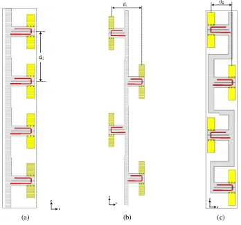
antenna element. The detail parameters for the final optimal antenna simulated by HFSS 15 are listed:
La = 45 mm, Lb = 38 mm, Ld = 94 mm, Lab = 45 mm, Wa = 2.7 mm, Wb = 1.88 mm, Wd = 18 mm,
Wg = 9 mm, Gap= 1 mm. Consequently, the impedance bandwidth of the dipole antenna for VSWR ≤ 2 is about 50%, as shown in Fig. 2(a). As can be seen from Fig. 2(b), the antenna element has unidirectional radiation pattern because of the influence of the ground.
2.2. Evolution of the Array
In order to radiate vertically polarized wave, the wideband antenna element should be vertically placed. Besides, more elements should be used to form arrays for improving antenna gain. Three different arrays are explored and analyzed.
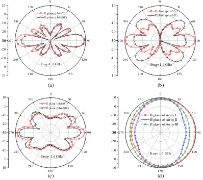
Figure 3 shows the evolution of the array with 4 wideband elements mentioned above. Four elements placed along the +zaxis form Array I with their beams both pointing to +yaxis. The distance between the array elements is set to d0 = 140 mm ≈ 0.75λ0. It is easy to see that the energy Array I radiates will not uniformly distribute in the azimuth plane due to the unidirectional radiation pattern of the element, as shown in Fig. 4(a). The gain in the +yaxis is 5 dB larger than that in the−yaxis. Then, to improve this, Array II is proposed, as shown in Fig. 3(b), with the second and fourth elements in Array I rotated 180 degrees around thez axis while the other parameters remain unchanged. The distance in the y axis between the array elements in Array II is set to d1 = 104 mm ≈ 0.55λ0. Though Array II improves the energy distribution in they axis, itsEplane at phi = 90◦ deteriorates due to large spacing between elements in the y axis direction, still leading to uneven energy coverage in the azimuth plane, as shown in Fig. 4(b). Finally, Array III is proposed, as shown in Fig. 3(c), with the distance between the array elements in the y axis decreases from d1 to d2 = 52 mm ≈ 0.28λ0. It is worth mentioning that the ground bends into Z shape. From Fig. 4(c), we can see that the E plane at phi = 90◦ and
(a) (b) (c)
-30 -20 -10 0 10 0 30 60 90 120 15 0 180 21 0 240 270 300 33 0 -30 -20 -10 0 10
E plane(ph i=00
) E plane(ph i=900)
Freq=1. 6 GHz
-30 -20 -10 0 10 0 30 60 90 120 15 0 180 21 0 240 270 300 33 0 -30 -20 -10 0 10
E plane(ph i=00
) E plane(ph i=900
)
Freq= 1. 6 GHz
-30 -20 -10 0 10 0 30 60 90 120 15 0 180 21 0 240 270 300 33 0 -30 -20 -10 0 10
E plane(ph i=00
) E plane(ph i=900
)
Freq= 1. 6 GHz
-30 -20 -10 0 10 0 30 60 90 120 15 0 180 21 0 240 270 300 33 0 -30 -20 -10 0 10
H plane of Array I H plane of Array II H plane of Array III
Freq= 1.6 GHz
(a) (b)
(c) (d)
Figure 4. The radiation patterns of different arrays at 1.6 GHz. (a) E planes of Array I. (b)E planes
of Array II. (c)E planes of Array III. (d)H planes of Array I, II and III.
the energy distribution in the y axis of Array III are improved compared to that of Array II. Fig. 4(c) shows theH planes of the three different arrays at 1.6 GHz. It is apparent that Array III has the most uniform radiation energy in the azimuth plane among these three arrays.
2.3. Integrated Feeding Network
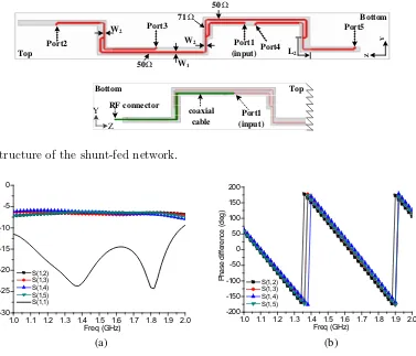
Shunt-fed network can provide the elements with coincident excitation. Thus a shunt-fed feeding network is designed to feed Array III, and its structure is shown in Fig. 5. The network adopts microstrip transmission line to integrate with the elements which has a common ground with the antenna elements. The network has an input port (denoted by Port 1) connected to the coaxial cable and four output ports (denoted by Ports 2, 3, 4 and 5) connected to the four elements. The characteristic impedances of all the ports are set to 50 Ω, and the widths of the strip lines connected to them are set to W1 (2.7 mm). To make a good matching condition at each junction, there is an impedance transformation line with a characteristic impedance of 70 Ω. Its length is L2 (about 0.25λg), and its width is W2 (1.5 mm).
174 Yang Z Y Port1 (input) Port2 Port3 Port4 Port5 W1 W2 71Ω 50Ω 50Ω W2 L2 coaxial cable RF connector Y Z Port1 (input) Top Bottom Bottom Top
Figure 5. Structure of the shunt-fed network.
1.0 1.1 1.2 1.3 1.4 1.5 1.6 1.7 1.8 1.9 2.0 -30 -25 -20 -15 -10 -5 0 M a g n itu d e o f S-Pa ra m e te rs ( d B) Freq (GHz) S(1,2) S(1,3) S(1,4) S(1,5) S(1,1)
1.0 1.1 1.2 1.3 1.4 1.5 1.6 1.7 1.8 1.9 2.0 -200 -150 -100 -50 0 50 100 150 200 P h as e di ff e re nc e ( d eg) Freq (GHz) S(1,2) S(1,3) S(1,4) S(1,5) (a) (b)
Figure 6. Simulated EM S-parameters and phase difference of the feeding network. (a) EM S
-parameters. (b) Phase difference.
2.4. Improving of the Unevenness
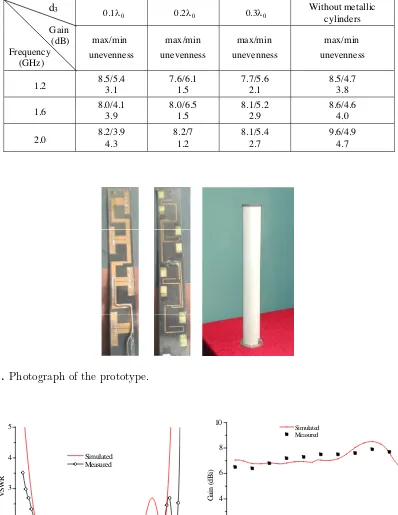
As we can see from Figs. 4(c) and (d), it is found that it has almost the same energy distribution in the +y axis as in the −y axis due to the symmetry of the antenna structure, so does it in the x axis. It is predictable that the gain in the x axis is larger than that in the y axis due to the unidirectional performance of the elements. Thus, the unevenness in the azimuth plane of Array III is still not good enough. To further decrease the large energy distribution discrepancy in the y axis and x axis of the presented antenna, two metallic cylinders that are used as reflectors are placed parallel to the z axis in the +x axis and −x axis, respectively, with a distance of d3 from the z axis. Actually, in this paper, the two metallic cylinders act as two passive dipoles. Their lengths and diameters affect the mutual impedance between the passive dipole and the active dipole, which further affect the radiation pattern of the array [24]. By properly optimizing the location and the length of the metallic cylinders, the omnidirectionality in the horizontal plane can be improved. Their lengths are about 2.8λ0 which corresponds to the length of the four-element array, and their diameters are 2 mm after optimization. Table 1 shows the unevenness in the azimuth plane of Array III with metallic cylinders with different distances (d3 = 0.1λ0, 0.2λ0 and 0.3λ0) from thez axis. From Table 1 we can see that the unevenness is about 4 dB in the azimuth plane without metallic cylinders. When the metallic cylinders are added, the unevenness is improved. The final optimal distance is d3 = 0.2λ0, and the optimal unevenness is about 1.5 dB.
3. EXPERIMENTAL RESULTS
Table 1. Gain and unevenness versus different d3.
d3
Gain (dB) Frequency
(GHz)
Without metallic cylinders
max/min unevenness
max /min unevenness
max/min unevenness
max/min unevenness
1.2 8.5/5.4 3.1 7.6/6.1 1.5 7.7/5.6 2.1 8.5/4.7 3.8
1.6 8.0/4.1 3.9 8.0/6.5 1.5 8.1/5.2 2.9 8.6/4.6 4.0
2.0 8.2/3.9 4.3 8.2/7 1.2 8.1/5.4 2.7 9.6/4.9 4.7 0.1O 0.2O 0.3O
Figure 7. Photograph of the prototype.
1.0 1.1 1.2 1.3 1.4 1.5 1.6 1.7 1.8 1.9 2.0 2.1 1
2 3 4 5
VSW
R
Freq (GHz) Simulated Measured
1.0 1.1 1.2 1.3 1.4 1.5 1.6 1.7 1.8 1.9 2.0 0
2 4 6 8 10
Ga
in
(
dB
i)
Freq (GHz)
Simulated Measured
(a) (b)
176 Yang
radome were used in measurements. The total size of the antenna is about 0.45λ0 ×0.45λ0 ×2.8λ0. The measurements were carried out by a network analyzer (Agilent E8363B) and a far-field measured system in an anechoic chamber.
Figure 8(a) shows the measured and calculated VSWR against frequency for the proposed antenna. The measured bandwidth for VSWR≤2 is 56% (1.12–2 GHz) which is slightly wider than the simulated one of 47% (1.15–1.85 GHz). The little difference is caused by the acceptable manufacturing tolerance. Fig. 8(b) depicts the measured and calculated gains versus frequency in the +x axis. As shown in
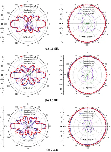
-40 -30 -20 -10 0 0 30 60 90 12 0 15 0 180 21 0 24 0 27 0 30 0 33 0 -40 -30 -20 -10 0 Simulated co-pol Measured co-pol Simulated cr-pol Measured cr-pol XOZ plane -40 -30 -20 -10 0 0 30 60 90 12 0 150 180 210 24 0 270 30 0 330 -40 -30 -20 -10 0 XOY plane -40 -30 -20 -10 0 0 30 60 90 12 0 15 0 180 21 0 24 0 27 0 30 0 33 0 -40 -30 -20 -10 0 XOZ plane -40 -30 -20 -10 0 0 30 60 90 12 0 150 180 210 24 0 270 30 0 330 -40 -30 -20 -10 0 XOY plane -40 -30 -20 -10 0 0 30 60 90 120 150 180 210 240 270 300 330 -40 -30 -20 -10 0 XOZ plane -40 -30 -20 -10 0 0 30 60 90 12 0 150 180 210 24 0 270 30 0 330 -40 -30 -20 -10 0 XOY plane
(a) 1.2 GHz
(b) 1.6 GHz
(c) 2 GHz
Simulated co-pol Measured co-pol Simulated cr-pol Measured cr-pol Simulated co-pol Measured co-pol Simulated cr-pol Measured cr-pol Simulated co-pol Measured co-pol Simulated cr-pol Measured cr-pol Simulated co-pol Measured co-pol Simulated cr-pol Measured cr-pol Simulated co-pol Measured co-pol Simulated cr-pol Measured cr-pol
Figure 9. Simulated and measured radiation patterns in the (a) elevation (Φ = 0◦) and (b) azimuth
Fig. 8(b), the measured gain is about 6.5 dBi across the frequency from 1.25 GHz to 2.0 GHz with a peak gain of 7.7 dBi at 1.85 GHz. The gain in the low operating band is slightly smaller than the simulated one. The discrepancy between the simulated and measured gains is likely due to the manufacturing and measurement errors.
Figure 9 shows the measured and calculated radiation patterns in the elevation plane (xoz plane) and azimuth (xoy plane) plane at 1.2, 1.6 and 2 GHz respectively. As can be seen from Fig. 9, the proposed antenna operates with good omnidirectional radiations. The beam pointing is stable when operating frequency changes. The gain variations in the azimuth planes are 1.5 dB, 1.6 dB, 2.0 dB respectively at the three frequencies which is slightly higher than the simulated ones due to the fabrication tolerance. The cross-polarized levels are less than −20 dB in all directions of horizontal planes.
4. CONCLUSION
A wideband omnidirectional VP antenna is proposed in this paper. A wideband printed dipole antenna with integrated balun used as array element is introduced to increase the impedance bandwidth significantly. The antenna array constructed by four wideband antenna elements is designed to achieve high gain. The evolution of the array is explored and discussed to obtain small gain variation in the azimuth plane. Furthermore, a shut-fed network integrated with the balun is adopted to feed the array. Finally, two metallic cylinders used as reflectors are employed to further improve the unevenness. A prototype of the antenna is designed, fabricated, and measured to validate the performance. Measured results show that the impedance bandwidth for VSWR ≤2 is 56% (1.12–2 GHz). The measured gain is above 6.5 dB, and the out-of-roundness of the antenna is less than 2 dB across the operation band. Therefore, the proposed antenna can be a good candidate for the various communication systems due to its advantages of simple structure, wide bandwidth and excellent radiation properties.
REFERENCES
1. Sierra-Perez, M., F. L. Heras-Andres, and J. A. G. D. Lope, “Low-cost printed collinear array antenna,” IEEE Antennas and Propag. Magazine., Vol. 43, No. 5, 23–30, 2001.
2. Hsiao, F.-R. and K. L. Wong, “Omnidirectional planar folded dipole antenna,” IEEE Trans. Antennas Propag., Vol. 52, No. 7, 1898–1902, 2004.
3. Zivanovic, B., T. M. Weller, and C. Costas, “Series-fed microstrip antenna arrays and their application to omni-directional antennas,”IEEE Trans. Antennas Propag., Vol. 60, No. 10, 4954– 4959, 2012.
4. Wei, K., Z. Zhang, B. W. Chen, et al., “A triband shunt-fed omnidirectional planar dipole array,” IEEE Antennas Wireless Propag. Lett., Vol. 9, 850–853, 2010.
5. Lau, K. F. and K. M. Luk, “A wideband monopolar wire-patch antenna for indoor base station applications,” IEEE Antennas Wireless Propag. Lett., Vol. 4, 155–157, 2005.
6. Row, J.-S., S.-H. Yeh, and K.-L. Wong, “A wide-band monopolar plate-patch antenna,” IEEE Trans. Antennas Propag., Vol. 50, 1328–1330, 2002.
7. Judasz, T. J. and B. B. Balsley, “Improved theoretical and experimental models for the coaxial colinear antenna,” IEEE Trans. Antennas Propag., Vol. 37, No. 3, 289–296, 1989.
8. Kiang, J. F., “Analysis of linear coaxial antennas,”IEEE Trans. Antennas Propag., Vol. 46, No. 5, 636–642, 1998.
9. Bancroft, R. and B. Bateman, “An omnidirectional planar microstrip antenna,” IEEE Trans. Antennas Propag., Vol. 52, No. 11, 3151–3153, 2004.
10. Chen, X., K. Huang, and X. B. Xu, “A novel planar slot array antenna with omnidirectional pattern,” IEEE Trans. Antennas Propag., Vol. 59, No. 12, 4853–4857, 2011.
178 Yang
12. Edward, B. and D. Rees, “A broadband printed dipole with integrated balun,”Microw. J., 339–344, May 1987.
13. Li, R. L., T. Wu, B. Pan, et al., “Equivalent-circuit analysis of a broadband printed dipole with adjusted integrated balun and an array for base station applications,” IEEE Trans. Antennas Propag., Vol. 57, No. 7, 2180–2184, 2009.
14. Zhang, Z.-Y. and C.-B. Zhang, “Wideband omnidirectional printed dipole antenna with coupling feed for wireless communication applications,” Progress In Electromagnetics Research C, Vol. 38, 89–99, 2013.
15. Lu, J.-H., S.-W. You, and H.-M. Chin, “Planar dual-band dipole array for LTE/WiMAX access points,” Proceedings of ISAP 2014, 329–330, 2014.
16. Yu, Y. F., J. Xiong, and R. Wang, “A wideband omnidirectional antenna array with low gain variation,”IEEE Antennas Wireless Propag. Lett., Vol. 15, 386–389, 2016.
17. Wang, H., S. He, and Y. F. Yu, “A wideband omnidirectional antenna array,” IEEE Antennas Wireless Propag. Lett., Vol. 15, 386–389, 2016.
18. Puente, C., J. Anguera, and C. Borja, “Dual-band dual-polarized antenna array,” US Pat. 6937206B2, 2005.
19. Jayasinghe, J. W., J. Anguera, and D. N. Uduwala, “A high-directivity microstrip patch antenna design by using genetic algorithm optimization,”Progress In Electromagnetics Research C, Vol. 37, 131–144, 2013.
20. Jayasinghe, J. W., D. N. Uduwala, and J. Anguera, “Increasing the directivity of a microstrip patch array by genetic optimization,” Journal of National Science Foundation, Vol. 43, No. 1, 83–89, 2015.
21. Robers, W. K., “A new wideband balun,”Proceedings of the IRE, Vol. 45, 1628–1631, 1957. 22. Baeer, R. and J. W. Wolfe, “A printed circuit balun for use with spiral antennas,” IRE Trans. on
MTT, Vol. 8, 319–325, 1960.