Identification of Structural Changes in Protocols
to Evaluate Bandwidth Utilization
Vani.K Maitraye.M
Assistant Professor UG Student
Department of Computer Science & Engineering Department of Electronics and Communication Engineering Saveetha Engineering College, Thandalam Saveetha Engineering College, Thandalam
Abstract
Protocol analysis is the process of capturing and analyzing the packets in a live environment in order to identify any unusual activities like presence of Trojans, root kits or other activities initiated by hackers. It can be used to find out delay in network communications, congestion experienced in the network, source and destination ports and other critical parameters of packets including MTU and signatures. In this paper, Protocol analysis is done by capturing the packets in transit, from a live network environment using network packet analyzing, and to identify protocol manipulation by hackers and unusual communications, attack signatures, unauthorized sniffing or ping sweep, scanning and hacker behavior / pattern. The result shows evaluation of bandwidth utilizations and an effective way of identifying threats.
Keywords: ARP Request, Bandwidth utilization, DNS and Network forensics, Protocol Analysis
________________________________________________________________________________________________________ I. INTRODUCTION
When two machines are communicating in a network, the first packet transmitted is ARP Request. It is broadcasted to all machines for getting the destination machine’s MAC address, the MAC address specified in the APR Request packet is compared with the destination machine’s MAC address. If they match then an ARP Reply packet is sent by the destination machine. If the MAC address is not specified in the ARP Request, then the machines will compare the IP addresses. If the IP addresses matches then it will send an ARP Reply packet otherwise it will drop the packet which is depicted in Fig. 1 [1].
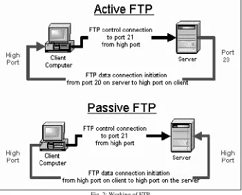
FTP does the connection and transmission through the ports 20 and 21, Port number 20 is used for data connection and 21 is used for control connection which is shown in Fig. 2. During file transmission the client machine specifies the port number through which the FTP server should transfer the data. The client machine communicates with DNS Server for getting the IP addresses of the web servers. DNS server provides the IP address of the web server using which the client machine communicates with web server [2].
Fig. 2: Working of FTP
The logs of various perimeter devices (Firewall, Domain Controllers, Servers, hosts) are analyzed to identify hacker behavior or the signatures of virus or worms or any malicious communications. These logs are recorded after the activity is over [3]. The delay in analyzing such logs causes sufficient damage before identification of the threat. These are not live and hence it is very difficult to mitigate the attacks.
Protocol analysis has been done by capturing the packets in transit, from a live network environment using network packet analyzers like Wireshark, Network minor or any other sniffing tool. This enables user to identify protocol manipulation by hackers and unusual communications, attack signatures, unauthorized sniffing or ping sweep, scanning and hacker behavior per pattern.
II. PACKET CAPTURING
The packet capturing is done by the client, it sends the ARP Request to identify the DNS Machine and the DNS responds with an ARP Response. The client machine communicates with DNS Server for getting the IP address of the web server. DNS server provides the IP address of the web server then the client machine communicates with web server. This can be done by the following steps
1) Client sends the ARP Request to identify the DNS Machine 2) DNS sends the ARP Response
3) Client sends DNS Request 4) DNS send DNS Response
5) Client sends the ARP Request for web server 6) Web server sends the ARP Response 7) Three way handshaking is done.
TCP(SYN)
TCP(SYN,ACK)
TCP(ACK)
8) Client sends HTTP Request
9) Web server sends the HTTP Response
III. PROTOCOL ANALYSIS
Analysis of ARP-Address Resolution Protocol, a network layer protocol used to convert an IP address into a physical address (called a DLC address), such as an Ethernet address. A host wishing to obtain a physical address broadcasts an ARP request onto the TCP/IP network. The host on the network that has the IP address in the request then replies with its physical hardware address. When an incoming packet destined for a host machine on a particular local area network arrives at a gateway, the gateway asks the ARP program to find a physical host or MAC address that matches the IP address.
The ARP program looks for the address in the ARP cache and if it finds the address, the packet can be converted to the right packet length and format and sent to the machine. If the IP address is not found in the ARP cache, ARP broadcasts a request packet in a special format to all the machines on the LAN to see if any machine knows that it has that IP address associated with it. A machine that recognizes the IP address as its own replies to the sender and ARP updates the ARP cache for future reference and then sends the packet to the MAC address which is replied. Fig. 3 shows the ARP header with bit values where the ARP information is stored which will be analyzed in the captured packets.
0 15
7 31
Hardware Type Protocol Type
Hardware Address Length Protocol Address
Length Opcode
Sender Hardware Address
Sender Protocol Address (bytes 3-4) Target Hardware Address
Target Protocol Address Fig. 3: ARP header
TCP is a very important protocol in the Internet. More than half of the traffic in Internet uses TCP.
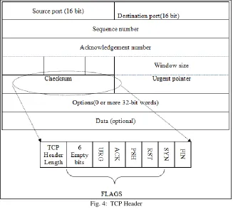
TCP Packet Structure
TCP Packet = TCP Header (20 bytes) + DATA (max of 65,495).
Number of words (w) is included in the TCP Header length (n) = w x n = 20byte.
In the above packet = 32 x 5 = 160bits /8 = 20bytes (default word length = 32bit)
The size of header indicates the start of the data.
Sequence and Acknowledge numbers are both 32bit in size.
The dashed lines between TCP Header and flags are empty 6bits and are not used.
Next to the empty 6bits are 1bit flags.
Flags field:
URG – Urgent Flag
ACK – Acknowledge Flag
PSH – Push Flag
RST – Reset Flag
SYN – Sync Flag
FIN – Finish Flag
Window size indicates the available buffer memory in the stack for communication.
Checksum is used to calculate the integrity of the TCP Segment
Urgent pointer is used along with the URG flag. It tells the receiving end where exactly the priority ends for the Data.
Options field includes few more parameters.
Data field is where the actual data/payload from the upper layers is stored.
URG
Urgent flag, it very rarely used in today’s protocols, it informs the receiving end about a priority data in the TCP segment. This flag is set along with the Urgent Pointer which informs when the priority ends for the data in the segment.
ACK
PSH
Push flag is used to push the data without any intermediate buffering (storing). In a TCP header if the PSH flag is set to 1 then it will not be buffered at any intermediate nodes, it will be simply pushed into the network without any intermediate buffering.
RST
Reset flag is used to reset/teardown an existing/established TCP session.
Example: When a service is running on a network port e.g. http on port 80, it runs its corresponding application service. When a remote machine tries to access this service it initially establishes a TCP connection to this port using 3-way handshake. If the http service is stopped on this port, it interrupts the connection and acknowledges to the requesting machine with a TCP RST flag set to 1. Another situation is when we are actively working on, for example a Telnet session, and if by mistake if we close the telnet window the telnet service on the host machine’s port 23 will stop and it immediately sends a TCP with RST flag set to 1 and once the remote machine receives this, it will tear down the connection without any delay or acknowledgement.
SYN
SYN flag is a well-known flag in TCP and is used to initiate a TCP session. Before the actual data starts to flow, a TCP segment with 0 data bytes are sent to the remote machine with the SYN flag is set to 1, after the three way handshake a dedicated session is established between the source machine and the target machine for the actual data to transfer.
Example: When opening any website the first step done by the TCP protocol is sending a SYN packet (though initially a DNS query is sent for the name resolution). And once a session is established then the data starts flowing, eventually presenting with the website, considering that it is available. Anything can go wrong in this transmission, in such cases we might get several errors/messages on the browser based on the nature of the issue. A simplified 3-way TCP handshake is shown below.
FIN
Finally the FIN flag is used to negotiate between the peer systems that the communication is over and they can drop the connection/session gracefully. Basically, it tears down the TCP virtual connection. FIN is a 4-way handshake which appears in the last packet of a session. Fig. 4 describes each flag analysis in the TCP packet.
Fig. 4: TCP Header
Fig. 5: UDP Header
ICMP is an error reporting protocol which is used to report to the source IP address when network faces the network devices problems which prevents delivery of IP packets. Any IP network device has the capability to send, receive or process ICMP messages. ICMP is not a transport protocol that sends data between systems. While ICMP is not used regularly in end-user applications, it is used by network administrators to troubleshoot Internet connections in diagnostic utilities including ping and trace route. ICMP header is shown in Fig. 6.
Fig. 6: ICMP Header
IV. IDENTIFICATION OF CHANGES IN PARAMETER
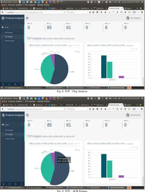
Fig. 8: TCP – Flag Analysis
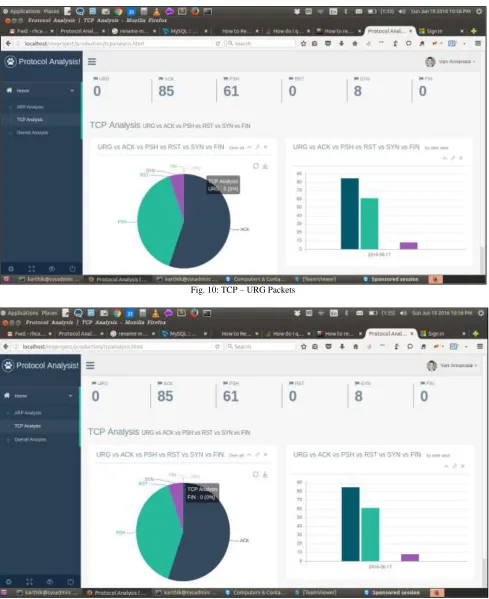
Fig. 10: TCP – URG Packets
Fig. 12: TCP – RST Packets
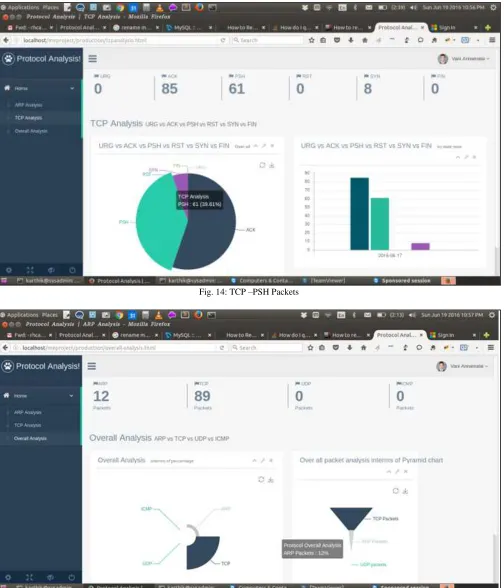
Fig. 14: TCP –PSH Packets
Fig. 15: Overall Analysis
V. RESULT AND DISCUSSION
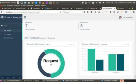
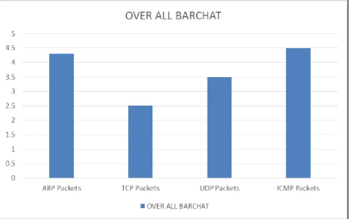
The stored information in the table are analyzed and graphical output is generated. In ARP Packets the number of Response and Request packets are analyzed which is shown in Fig. 16. In TCP packet the number of ACK, SYN, PSH, RST, FIN are analyzed and shown in Fig. 17. Finally overall analysis is done for TCP, ARP, UDP and ICMP packets which is shown in Fig. 18.
Table – 1 ARP Packet Contents
Source Address Destination Address Opcode Date 192.168.1.6 192.168.1.5 Request 2016-06-17 21:30:45 192.168.1.5 192.168.1.8 Request 2016-06-17 21:31:30 192.168.1.5 192.168.1.9 Request 2016-06-17 21:32:11 192.168.1.9 90:48:9a:f5:a7:B1 Response 2016-06-17 21:34:08 192.168.1.9 192.168.1.5 Request 2016-06-17 21:34:27 192.168.1.5 C8:3a:35:c3:70:47 Response 2016-06-17 21:35:z
Fig. 16: ARP Packet Analysis
Fig. 18: Overall Packets Analysis
VI. CONCLUSION
In this paper the protocol analysis is done by capturing the packets in transit, from a live network environment using network packet analyzer and Wireshark, this enables the user to identify protocol manipulation by hackers and unusual communications, attack signatures, unauthorized sniffing or ping sweep, scanning and hacker behavior / pattern. These captured packets were analyzed continuously for optimum bandwidth utilization, to mitigate identified threats and to change Baseline configuration to strengthen security. This analysis will be useful for information gathering, legal evidence identification and intrusion detection in the area of digital forensics.
REFERENCES
[1] Circiumarescu, L.D.; Predusca, G.; Angelescu, N.; Puchianu, D.,”Comparative Analysis of Protocol RIP, OSPF, RIGRP and IGRP for Service Video
Conferencing, E-mail, FTP, HTTP, Control Systems and Computer Science (CSCS), Pages: 584 - 589 IEEE Conference Publications, 2015.
[2] Tapio Levä, Henna Suomi ,”Techno-economic feasibility analysis of Internet protocols: Framework and tools”, Computer Standards & Interfaces, Volume
36, Issue 1, Pages 76-88,November 2013.
[3] Minitrack, Nance, Kara; Bishop, Matt ,”Introduction to Digital Forensics”, 48th Hawaii International Conference on : Education, Research, and Practice