Electrooxidation of Formic Acid and Formaldehyde
on the Fe
3
O
4
@Pt Core-Shell
Nanoparticles/Carbon-Ceramic Electrode
Habibi, Biuck*
+; Ghaderi, Serveh
Electroanalytical Chemistry Laboratory, Department of Chemistry, Faculty of Sciences, Azarbaijan Shahid Madani University, Tabriz, I.R. IRAN
ABSTRACT: In the present work, the electrooxidation of formic acid and formaldehyde; potentially important fuels for future fuel cells, was investigated on the Fe3O4@Pt core-shell nanoparticles/carbon-ceramic electrode (Fe3O4@Pt/CCE). The Fe3O4@Pt nanoparticles were prepared via a simple and fast chemical method and their surface morphology, nanostructure properties, chemical composition, crystal phase, and electrochemical behavior were investigated by scanning electron microscope, transmission electron microscope, X-ray diffraction, energy dispersive X-ray spectroscopy and electrochemical methods, respectively. Then the electrocatalytic activity of the Fe3O4@Pt/CCE toward the oxidation of formic acid and formaldehyde was studied in details. The primary electrochemical analysis shows that the Fe3O4@Pt/CCE has superior catalytic activity and stability for formic acid and formaldehyde oxidation compared to Pt-alone nanoparticles on the carbon-ceramic electrode (Pt/CCE). The present investigation demonstrates that the Fe3O4@Pt/CCE electrocatalyst may play a significant role in future fuel cell applications.
KEYWORDS:Fe3O4@Pt nanoparticles; Core-shell; Carbon-ceramic electrode; Electrooxidation; Formic acid; Formaldehyde; Fuel cell.
INTRODUCTION
Future energy concerns demand a transition from fossil fuels to new energy sources that are more environmentally benign, eco-friendly and renewable. A promising way for accomplishing this goal is to utilize fuel cells to convert the chemical energy directly into electricity. The advantages of using fuel cells for the production of electricity in clean, environmentally friendly, silent and efficient way have been demonstrated in the literatures [1, 2]. In the recent years, development of the fuel cells that operate based on direct oxidation
of small organic molecules without any external reforming has attracted remarkable interest because of their applications as the alternative power sources, ranging from portable power for consumer electronics to transport applications. This technology is more effective than the conventional power sources and can provides cleaner and cheaper energy depending on the chosen fuel [3-5]. The electrooxidation reaction of small organic molecules such as methanol [6], ethanol [7, 8], formic acid and formaldehyde [9, 10] with potential application
* To whom correspondence should be addressed.
as fuel has received much attention for fuel cells due to their attractive properties. With regard to fuel cell reactions, formic acid electrooxidation is gaining more and more attention, not only for its model role in the electrooxidation of small organic molecules, but also it is a promising fuel that was used in direct formic acid fuel cells (DFAFCs). DFAFCs are noteworthy as proper power sources for portable electronic devices, because formic acid is non-toxic, not inflammable, has high power density, low fuel crossover and thus its storage and transportation are safe [11-13]. On the other hand, as noticed from the structure, formaldehyde is the simplest organic molecules and often considered as a model molecule in the investigations of the electrooxidation behavior of larger organic species. In addition, knowledge of the reactivity of formaldehyde in an electrochemical environment is important for various applications including fuel cells [14, 15] and electrochemical detection [16]. Therefore, the electrooxidation of formaldehyde at various electrocatalysts has been receiving much attention [17, 18]. In addition, a series of studies shows that formaldehyde is one of the main products of methanol electrooxidation and further studies of formaldehyde oxidation are necessary for better understanding of methanol oxidation. For these reasons, formaldehyde electrooxidation had been studied under a wide range of conditions at the various electrocatalysts [19-21]. Moreover, recent data show that the formaldehyde fuel cells are attractive alternative for the proton exchange membrane fuel cell (PEMFCs) applications [22-24].
One of the key problems in PEMFCs and DFAFCs is the development of anodic materials with high electroactivity toward the oxidation of formaldehyde and formic acid. Platinum (Pt) is regarded as a most common and effective electrocatalyst for oxidation of these fuels because of its superior catalytic activity [25]. However, despite the advantages, the high cost and poor poison tolerance still prevent the commercial utilization of Pt and Pt-based electrocatalysts. Great attempts in the recent years have been dedicated to construction of functional Pt nanostructures with designed shapes and sizes in order to obtain higher electrocatalytic activity and better Pt utilization [26, 27]. A new rout to prepare highly active and durable electrocatalysts with low Pt loading involves the production of bimetallic nanoparticles with a core-shell structure [28, 29]. Bimetallic nanoparticles with a core-shell structure display dual physicochemical
performance [28, 30, 31], by inheriting the functional properties of both the core metal as well as the shell metal, thus gradually becoming a main class of materials in catalysis research. Compared with traditional precious metal electrocatalysts and alloy electrocatalysts, bimetallic core-shell nanoparticles composed of transition metal core and precious metal shell are considered as the potential candidates for electrocatalysis [28, 32, 33]. As a result, core-shell structure is an effective and useful way to increase the utilization efficiency of precious metal electrocatalysts. Pt-based core-sell structure electrocatalysts display unique advantages, such as low Pt loading and high output power density and have attracted more and more interest in recent years because of their suitable and novel electrocatalytic properties as the anodes or cathodes in the fuel cells applications [28, 32, 34-36].
In this work, we report the preparation of the Fe3O4@Pt core-shell nanoparticles by a facile and fast
chemical method. The structure, morphology, composition and electrochemical properties of the prepared core-shell nanoparticles were characterized by X-Ray Diffraction (XRD), Scanning Electron Microscope (SEM), Energy Dispersive X-ray (EDX) spectroscopy Transmission Electron Microscope (TEM) and electrochemical methods. Electrocatalytic activity of the obtained electrocatalyst, Fe3O4@Pt core-shell nanoparticles supported on the
carbon-ceramic electrode (Fe3O4@Pt/CCE), toward the
oxidation of formic acid and formaldehyde was assessed by voltammetric and chronoamperometric techniques. It was found that the Fe3O4@Pt/CCE was catalytically
more active than Pt/CCE and had satisfactory stability and reproducibility when stored in ambient conditions or continues cycling.
EXPERIMENTAL SECTION Reagents and materials
The chemical reagents including; H2PtCl6.5H2O,
Fe(NO3)3.9H2O, NaBH4, formic acid, formaldehyde,
H2SO4 and high purity graphite powder were purchased
from Merck corporation. Methyl trimethoxy silane (MTMOS) was from Fluka. All of the solutions were prepared using double distilled water.
Synthesis of Fe3O4@Pt nanoparticles
The Fe3O4@Pt nanoparticles were prepared using
and NaBH4 as reducing agent [37]. To acquire the Fe3O4
cores, the metallic salt solution [Fe(NO3)3.9H2O,0.02 M]
was added dropwise into the solution containing the reducing agent [NaBH4, 0.01 M] at room temperature and
mechanically stirred. The obtained product was separated by centrifugation at 3000 rpm and washed with double distilled water. To synthesis of the Fe3O4@Pt
nanoparticles, the Fe3O4 cores were suspended on a fresh
reducing solution of NaBH4 (0.01 M) and the solution of
the H2PtCl6.5H2O (0.02 M) was slowly added under
mechanically stirring and then the mixture was stirred for 30 min at 25 ◦C. During this period, the color of the mixture gradually turned black from orange, indicating that the Fe3O4@Pt nanoparticles have been formed.
Finally, the obtained product was separated by centrifugation at 3000 rpm, washed with double distilled water and dried [37].
Preparation of the Fe3O4@Pt/CCE electrocatalyst Carbon-Ceramic Electrode (CCE) was used as a substrate for the electrocatalyst supporting. The preparation of sol-gel derived CCE was the same as our previous works [38, 39]. Briefly, a portion of 0.9 mL MTMOS was mixed with 0.6 mL methanol and 0.6 mL of 0.5 M HCl as catalyst. The mixture was magnetically stirred for 45 min until a homogeneous solution resulted. Next, 0.3 g graphite powder was added and the mixture was mixed for several minutes (about 15 min). Subsequently, the homogenized mixture was tightly packed into a Teflon tube (with 3.9 mm inner diameter and 10 mm length) and dried for at least 24 h at room temperature. A copper wire was inserted through the other end to set up electric contact. The CCE surface was polished with 1500 emery paper and was rinsed with double distilled water. The Fe3O4@Pt/CCE electrocatalyst was prepared as follows:
20.0 mg of Fe3O4@Pt nanoparticles was ultrasonically
suspended in 5 ml solution containing double distilled water and 5% wt Nafion (50 µL) for about 30 min to obtain a well-dispersed ink. Then 5 µL of well-dispersed ink was quantitatively transferred onto the pre-polished CCE surface by using a micropipette and dried under ambient condition.
Materials characterization
XRD patterns were recorded by a Bruker AXS model D8 Advance (Karlsruhe, Germany) instrument, using
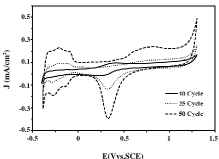
Fig. 1: Cyclic voltammograms of Fe3O4@Pt/CCE electrocatalyst
(10, 25 and 50th cycle) in 0.5 M H2SO4 electrolyte at scan rate
of 50 mV/sc.
Cu-Kα radiation source (1.54 Å) at 40 kV and 35 mA
at room temperature. The 2θ angular regions between 7◦ and 90◦ were explored at a scan rate of 5◦ min-1.
SEM was carried out on A LEO1430 vp (Carl Zeiss, Germany) instrument equipped with an EDX device. The particle shape and surface morphology of the electrocatalyst was confirmed by TEM, which was carried out on a Carl Zeiss 906 E (Cottingen, Germany) microscope operating at an accelerating voltage of 10 kV and grid size 200 mesh.
Electrochemical evaluations
All electrochemical measurements were conducted in a standard three-electrode electrochemical cell using an AUTOLAB PGSTAT-100 (potentiostat/galvanostat) equipped with a USB electrochemical interface and controlled by GEPS software. The electrocatalyst (Fe3O4@Pt/CCE or Pt/CCE) was used as a working
electrode. A platinum wire was used as a counter electrode and potentials were determined using a Saturated Calomel Electrode (SCE). All experiments were performed at room temperature in 0.5 M H2SO4
solution. Before electrochemical tests, pretreatment of the electrocatalyst was performed by cyclic voltammetry between -0.3 and 1.2 V for 50 cycles at a scan rate of 50 mV s-1 in 0.5 M H
2SO4 solution (Fig. 1). As can be seen, by
cycling of the potential in the subsequent scans, adsorption/desorption of hydrogen peaks and formation and reduction of surface Pt oxide peaks were grown and reached to final and stable form after 50 cycles.
-0.5 0 0.5 1 1.5
E(Vvs.SCE)
0.5
0.3
0.1
-0.1
-0.3
-0.5
J
(
mA
/c
m
RESULTS AND DISCUSSION
Physicochemical characterization of the Fe3O4@Pt nanoparticles
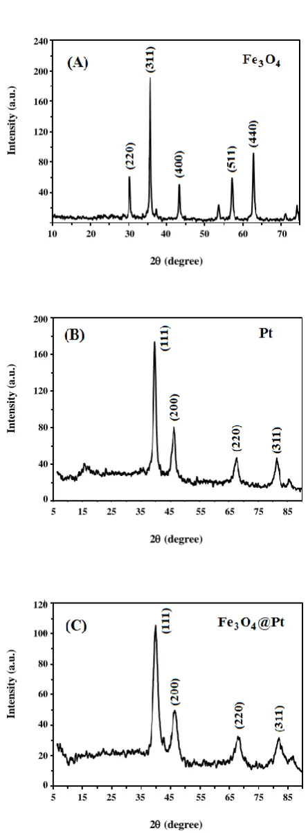
XRD analysis was used to the structural characterization of the Fe3O4@Pt nanoparticles. The
XRD patterns of the Fe3O4 cores, Pt-alone nanoparticles
and Fe3O4@Pt core-shell nanoparticles are displayed in
Fig. 2. The XRD pattern of the Fe3O4 cores [Fig. 2(A)]
has some diffraction peaks corresponded to the formation of ferric-ferrous oxide (FeO.Fe2O3) with a cubic
spinel-type phase structure [35]. The diffraction peaks at 2θ = 39.28◦, 35.68◦, 43.28◦, 57.12◦ and 62.76◦ are attributed
to the (220), (311), (400), (511) and (440) planes of the cubic spinel-type magnetite structure of Fe3O4 cores,
respectively [35, 40]. Fig. 2(B) shows the XRD pattern of the Pt-alone nanoparticles nanostructure. In this diffractogram, the (111), (200), (220) and (311) planes at 2θ = 39.9◦, 46.4◦, 67.6◦ and 81.7◦ are related to
face-centered-cubic (fcc) structure of Pt, respectively. The XRD pattern of the Fe3O4@Pt core-shell nanoparticles
(Fig. 2(C)) has four diffraction peaks centered at 2θ of about 39.96◦, 46.76◦, 67.96◦ and 81.36◦ which can be assigned to the (111), (200), (220) and (311) facets of the Pt face centered cubic (fcc) lattice structure, respectively. Due to the presence of Fe3O4 into the fcc structure of Pt,
the Pt reflections are shifted slightly to higher values of 2θ, which indicates a contraction of the lattice and the formation of Fe3O4@Pt core-shell nanoparticles [41, 42].
Based on the XRD results, it can be confirmed that the Fe3O4@Pt core-shell nanoparticles are composed of
a Fe3O4 core with Pt shell covering.
The surface morphology of the Fe3O4@Pt
nanoparticles was investigated by SEM and the corresponding result is shown in Fig. 3(A). As can be seen, the SEM image of the Fe3O4@Pt nanoparticles
shows uniform morphology, spherical structure and their sizes are around 20-30 nm. In order to specify the chemical composition of the Fe3O4@Pt nanoparticles
the EDX analysis was used [inset of Fig. 3(A)]. As seen in the inset of Fig. 3(A), the presence of only Pt element peaks in the EDX spectrum can be attributed to the fact that the surface of Fe3O4 cores was fully covered by a Pt
layer. On the other hand, the absence (or the minor presence) of Fe and O peaks confirms a complete coating of the Fe3O4 cores by the Pt shell. To more confirmation
of the core-shell structure of the Fe3O4@Pt nanoparticles,
Fig. 2: XRD patterns of (A) Fe3O4 cores, (B) Pt-alone
nanoparticles and (C) Fe3O4@Pt nanoparticles.
10 20 30 40 50 60 70
2 (degree)
240
200
160
120
80
40
0
In
te
n
si
ty
(
a
.u
.)
5 15 25 35 45 55 65 75 85
2 (degree)
200
160
120
80
40
0
In
te
n
si
ty
(
a
.u
.)
5 15 25 35 45 55 65 75 85
2 (degree)
120
100
80
60
40
20
0
In
te
n
si
ty
(
a
.u
Fig. 3: SEM image of (A) the Fe3O4@Pt core-shell nanoparticles (inset: EDX spectrum of Fe3O4@Pt core-shell nanoparticles) and
(B) TEM image of the Fe3O4@Pt core-shell nanoparticles (inset: particle size distribution from several different regions).
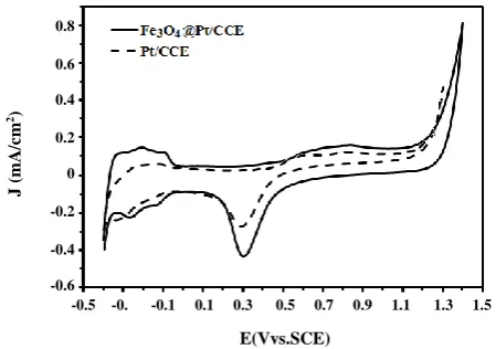
Fig. 4: Cyclic voltammograms of Fe3O4@Pt/CCE (black line)
and Pt/CCE (dashed line) in 0.5 M H2SO4 electrolyte at scan
rate of 50 mV s−1.
the TEM investigation was applied. Fig. 3(B) shows the TEM image of the Fe3O4@Pt nanoparticles. As seen
from the TEM image, the Fe3O4@Pt nanoparticles are
spherical in shape and have a spherical core-shell structure, with evenly distributed particles of similar size ranging from 20 to 30 nm as seen in inset of Fig. 3(B). The histogram [inset of Fig. 3(B)] for particle size distribution includes the analysis of several different regions of the sample.
Electrochemical characterization of the Fe3O4@Pt/CCE electrocatalyst
Electrochemical Active Surface Area (EASA) is a main factor in the characterization of the electrocatalysts and a conventional way of comparing electrocatalysts activities
to normalize the anodic or cathodic current in the electrocatalysis reactions [43, 44]. According to the humps at low potentials that are related to the adsorption/desorption of hydrogen on the Cyclic Voltammetry (CV) curves, EASA of the electrocatalysts was determined from CV curves by calculating the charge transfer involved in hydrogen adsorption/desorption [45, 46]. EASA of the Fe3O4@Pt/CCE electrocatalyst was determined by CV
profile which obtained in 0.5 M H2SO4 solution at a scan
rate of 50 mV/s, Fig. 4 (black line). For comparison, the CV of the Pt/CCE is also recorded in the same solution and is shown in Fig. 4 (dashed line). The typical anodic and cathodic peaks (humps) at low potentials are related to the adsorption/desorption of hydrogen on the Pt surface at the Fe3O4@Pt/CCE electrocatalyst. The anodic
peak and its corresponding cathodic peak in the potential range from 0.2 to 0.9 V are due to the formation and reduction of surface Pt oxide, respectively. Comparison of the CV grams of Fe3O4@Pt/CCE electrocatalyst and
Pt/CCE in Fig. 4 shows that both oxidation and reduction currents of the adsorption/desorption of hydrogen on the Fe3O4@Pt/CCE electrocatalyst are much higher than
those on the Pt/CCE. For the calculation of the EASA the following equation was used [47]:
EASA (m2 g-1 Pt) = Q
H / [Qref × Pt loading] (1)
In which QH indicates the coulombic integrated
charge associated with the hydrogen adsorption region (mC), Qref has a corresponding value of 0.21 mC/cm, which
is the charge for a monolayer adsorption of hydrogen on surface of Pt.
-0.5 -0. -0.1 0.1 0.3 0.5 0.7 0.9 1.1 1.3 1.5
E(Vvs.SCE)
0.8
0.6
0.4
0.2
0
-0.2
-0.4
-0.6
J
(
mA
/c
m
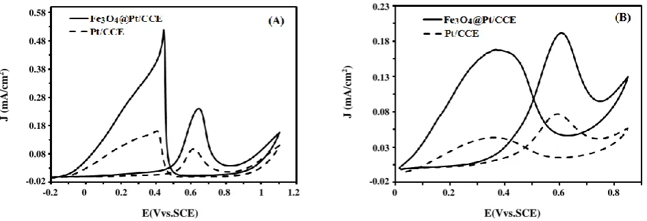
Fig. 5: Cyclic voltammograms of the Fe3O4@Pt/CCE (black line) and Pt/CCE (dashed line) in (A) 0.5 M H2SO4 + 0.2 M
formic acid and (B) in 0.5 M H2SO4 + 0.2 M formaldehyde at scan rate of 50 mV/s.
The roughness factor (Γ) is another important parameter that characterizes the electrocatalytic properties of an electrocatalyst. Γ is the ratio between the real surface area (SReal) and the geometric surface area
(SGeo) of an electrocatalyst, and EASA is SReal per unit
electrocatalyst loading [48]. SReal can be obtained from
charge for hydrogen adsorption as SReal = QH/Qref.
The SReal, Γ and EASA values for Fe3O4@Pt/CCE
electrocatalyst and Pt/CCE were calculated to be [11.47 cm2,
91.32 and 60.25 m2/g] and [3.90 cm2, 31.05 and 20.49 m2/g],
respectively. The EASA of the Fe3O4@Pt/CCE
electrocatalyst is about 3 times higher than that of the Pt/CCE, confirming that the core-shell electrocatalyst could improve the use ratio of the Pt metal [49, 50]. These results indicate the presence of large numbers of active sites on the surface of Fe3O4@Pt/CCE
electrocatalyst.
Electrooxidation of the formic acid and formaldehyde on the Fe3O4@Pt/CCE electrocatalyst
Electrooxidation of the formic acid and formaldehyde on the Fe3O4@Pt/CCE electrocatalyst was evaluated by
cyclic voltammetry. Fig. 5 shows the CVs of Fe3O4@Pt/CCE electrocatalyst in a 0.5 M H2SO4 solution
containing 0.2 M of these fuels. It can be seen that the electrooxidation these fuels (both for formic acid and for formaldehyde) on the Fe3O4@Pt/CCE electrocatalyst
associate with two well-defined oxidation peaks: one in the forward scan and the other in the backward scan. It is believed that the anodic peak in the forward scan
can be ascribed to the oxidation of freshly chemisorbed species coming from fuels adsorption, while another anodic peak in the backward scan is primarily associated with the removal of carbonaceous species not completely oxidized in the forward scan [51-53]. From the CVs in Fig. 5; the electrooxidation of formic acid (Fig. 5A) and the electrooxidation of formaldehyde (Fig. 5B) on the Fe3O4@Pt/CCE (black lines) and Pt/CCE (dashed lines),
it was concluded that the improved anodic peak current densities for these fuels oxidation on the Pt active sites at the Fe3O4@Pt/CCE with respect to the Pt/CCE might be
due to the effect of the geometric parameters induced by the formation of core-shell structure. This allows that a large number of catalytically active sites to be present on the available surface of the Fe3O4@Pt particles which is
in agreement with the obtained results; EASA of the Fe3O4@Pt/CCE electrocatalyst is about three times
higher than that of Pt/CCE. Furthermore, due to the synergetic effect between Fe3O4 and Pt, the inter-atomic
Pt-Pt distances on the Fe3O4@Pt/CCE electrocatalyst
might be changed, which can results in more facile fuel adsorption and oxidation due to the modified surface and electronic properties [54, 55]. The greater electrocatalytic activity of the Fe3O4@Pt/CCE with
respect to the Pt/CCE was also confirmed by the lower onset potential on it. Onset potential for formic acid and formaldehyde oxidation on the Fe3O4@Pt/CCE is about
100 mV less than Pt/CCE, which indicate that the breaking of C-H bonds of fuels and subsequent removal of intermediates such as COad by oxidation with
0 0.2 0.4 0.6 0.8
E(Vvs.SCE)
0.23
0.18
0.13
0.08
0.03
-0.02
J
(
mA
/c
m
2) 0.58
0.48
0.38
0.28
0.18
0.08
-0.02
J
(
mA
/c
m
2)
-0.2 0 0.2 0.4 0.6 0.8 1 1.2
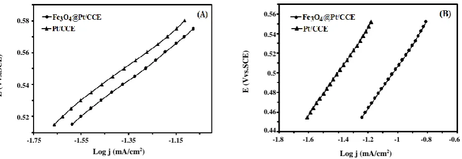
Fig. 6: Tafel plots of the Fe3O4@Pt/CCE (●) and Pt/CCE (▲) in (A) 0.2 M formic acid and
(B) 0.2 M formaldehyde at scan rate 10 mV/s.
OHad supplied by Pt-OH sites or other sources are much
easier on the Fe3O4@Pt/CCE electrocatalyst than on the
Pt/CCE [49, 56].
In order to further comparing of the electrocatalytic activity of the Fe3O4@Pt/CCE and Pt/CCE, the kinetic
parameters for the formic acid and formaldehyde electrooxidation on the Fe3O4@Pt/CCE and Pt/CCE
electrocatalysts were evaluated. The polarization curves are plotted according to E (V vs. SCE) versus log J (mA/cm-2) and shown in Fig. 6 [Fig. 6(A) for formic
acid electrooxidation on the Fe3O4@Pt/CCE (●) and
Pt/CCE (▲) and Fig. 6(B) for formaldehyde electrooxidation on the Fe3O4@Pt/CCE (●) and Pt/CCE
(▲) electrocatalysts], which are known as “Tafel plots” and follow the below Tafel Equation [57]:
ɳ = a + b log J (2)
a = −2.303RT log Jₒ/α n′F (3)
b = 2.303RT/α n′F (4)
The constants R and F denote the universal gas constant and the Faraday constant, respectively, T is the temperature (in K), α is the charge transfer coefficient of the reaction, Jₒ is the exchange current density, n′ is the number of electrons transferred in the rate-determining step and the value of b is the Tafel slope. The Tafel slopes on the Fe3O4@Pt/CCE and Pt/CCE electrocatalysts
are 201 and 203 mV/dec respectively for formic acid and 220 and 221 mV/dec respectively for formaldehyde (at 298 K). So the value of αn′ can be calculated by Eq. (4). The values of αn′ on the Fe3O4@Pt/CCE and Pt/CCE
electrocatalysts were obtained to be 0.31 and 0.29 respectively on the Fe3O4@Pt/CCE and Pt/CCE for
formic acid and 0.30 and 0.32 respectively on the Fe3O4@Pt/CCE and Pt/CCE for formaldehyde. The
rate-determining electron transfer is a one-electron process,
n′=1 [58]; thus, α values should be 0.31 and 0.30 on the
Fe3O4@Pt/CCE respectively for formic acid and
formaldehyde, and 0.29 and 0.32 on the Pt/CCE respectively for formic acid and formaldehyde [59]. From the values of the Tafel slope and αn′, a mechanism which going through the active intermediates with one electron exchange in the rate-determining step can be proposed [60, 61] for the electrooxidation of formic acid and formaldehyde and it can be concluded that the reaction pathway was principally the same for both electrocatalysts. By extrapolating the Tafel line, to the point where the overpotential equals zero, the exchange current density can be obtained. A higher exchange current density for electrochemical reactions implies a faster reaction, which is another important factor for efficient and good electrocatalyst performance [59-62]. Values of 2.03 × 10⁻² mA/cm2 and
0.63× 10⁻² mA/cm2 were obtained for the exchange
current density on the Fe3O4@Pt/CCE for formic acid and
formaldehyde, respectively and values of 1.64 × 10⁻² mA/cm2
and 0.49 × 10⁻² mA/cm2 were obtained on the
Pt/CCE for formic acid and formaldehyde, respectively. The Fe3O4@Pt/CCE electrocatalyst yielded a higher
exchange current density compared with the Pt/CCE electrocatalyst, which may be related to the improved electrocatalytic activity in the fuels electrooxidation reaction.
-1.8 -1.6 -1.4 -1.2 -1 -0.8 -0.6
Log j (mA/cm2)
0.56
0.54
0.52
0.5
0.48
0.46
0.44
E
(
V
v
s.
S
C
E
)
0.58
0.56
0.54
0.52
E
(
V
v
s.
S
C
E
)
-1.75 -1.55 -1.35 -1.15
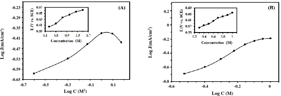
Fig. 7: The logarithmic plots of the peak current density at various fuel concentrations for (A) formic acid and (B) formaldehyde. Insets show E (V vs. SCE) in the forward scan versus fuel concentration (M) at a scan rate of 50 mV/s.
Effect of fuels concentration and scan rate on the electrocatalytic activity
The effect of fuel concentration on the electrooxidation of these fuels was investigated on Fe3O4@Pt/CCE electrocatalyst at a fixed H2SO4
concentration; 0.5 M. Fig. 7 shows the effect of fuel concentration on the anodic peak current density of formic acid (Fig. 7A) and formaldehyde (Fig. 7B) electrooxidation on the Fe3O4@Pt/CCE electrocatalyst.
According to the experimental data, the anodic peak current density increases with the increasing of the formic acid and formaldehyde concentration up to 1.0 and 0.9 M, respectively, after which it remains at almost constant values independent of the fuel concentration for formaldehyde and decreases at higher concentration for formic acid. This can be ascribed to the saturation of active sites with fuel that inhibits the OH- adsorption on
Pt sites and causes to a decrease of anodic peak current density [63]. On the other hand, when the fuel concentration increases, the forward oxidation peak potential (Ef) and backward oxidation peak potential (Eb)
shift toward positive potential (insets of Fig. 7). This may occur because; the poisoning rate of the Pt electrocatalyst increases with increasing the fuel concentration and the oxidative removal of the strongly adsorbed intermediates would shift to a more positive potential [64-66]. The logarithmic plot of the peak current density of fuel oxidation with its concentration produces a straight line of a slope equal to the order of the reaction with respect to fuel concentration according to the relation:
Rate α J = k Cn (5)
log J = log k + n log C (6)
where J is the peak current density, k is the reaction rate constant, C is the bulk concentration and n is the reaction order. The slope of the curve of log J (mA/cm2)
versus log C (M) is 0.35 and 1.05 for formic acid and formaldehyde, respectively. Therefore, the reaction order of formic acid and formaldehyde oxidation reaction is about 0.35 and 1.05 at the Fe3O4@Pt/CCE electrocatalyst,
respectively.
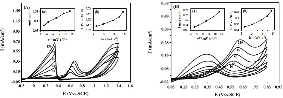
In order to explain the kinetic characterization of formic acid and formaldehyde oxidation on the Fe3O4@Pt/CCE electrocatalyst, a further investigation
was performed. The effect of scan rate on the electrooxidation of formic acid and formaldehyde was also studied and the obtained results are shown in Fig. 8 (A) and Fig. 8 (B), respectively. The results clearly indicate that the peak current density associated to fuel electrooxidation increases linearly with increasing of the scan rate. The relation between the peak current density obtained at the forward scan and square of root of scan rate (v1/2) is shown in the insets (a) of the Fig. 8. This
reveals that the electrooxidation of formic acid and formaldehyde on Fe3O4@Pt/CCE electrocatalyst is
a diffusion-controlled process [67]. Additionally, the Ef shifts positively with increasing scan rate (v).
A linear relationship can be obtained between Ef and ln (v),
as shown in the insets (b) of the Fig. 8. This indicates that the oxidation of formic acid and formaldehyde is completely an irreversible process [68]. Since the diffusion
-0.6 -0.4 -0.2 0
Log C (M)
0.2
0
-0.2
-0.4
-0.6
-0.8
L
o
g
J
(mA/
cm
2) -0.23
-0.29
-0.35
-0.41
-0.47
-0.53
-0.59
-0.65
L
o
g
J
(mA/
cm
2)
-0.7 -0.5 -0.3 -0.1 0.1
Fig. 8:Cyclic voltammograms of Fe3O4@Pt/CCE electrocatalyst in (A) 0.5 M H2SO4 + 0.2 M formic acid and
(B) 0.5 M H2SO4 + 0.2 M formaldehyde at different scan rates. Insets of (a): plots of the peak current density versus
the square root of scan rates and insets of (b): E (V vs. SCE) versus the ln v (mV/s).
coefficient of the fuels, D, which reflects the charge-transport rate within the liquid film near the electrocatalyst surface, is an important physiochemical property in the fuel cells science, its determination for formic acid and formaldehyde oxidation on the Fe3O4@Pt/CCE electrocatalyst could be useful. We knew
that for a completely irreversible reaction such as
electrooxidation of these fuels, the relationship between
diffusion coefficient and bulk concentration can be described by the following equation [69]:
J=2.99 ×10⁵ n′ (αn
α)1/2 CD1/2v1/2 (7)
where, J is the peak current density measured (mA/cm2),
D and C are the diffusion coefficient (cm2/s) and the
bulk concentration (mol/cm3), respectively. v is the
scan rate (mV/s), and n′ is the number of electrons transferred in the sum of the reactions. In this case,
the value of D was obtained as 9.4×10⁻⁷ cm2/s and
1.37×10⁻⁶ cm2/s on Fe
3O4@Pt/CCE electrocatalyst for
formic acid and formaldehyde, respectively [59, 70].
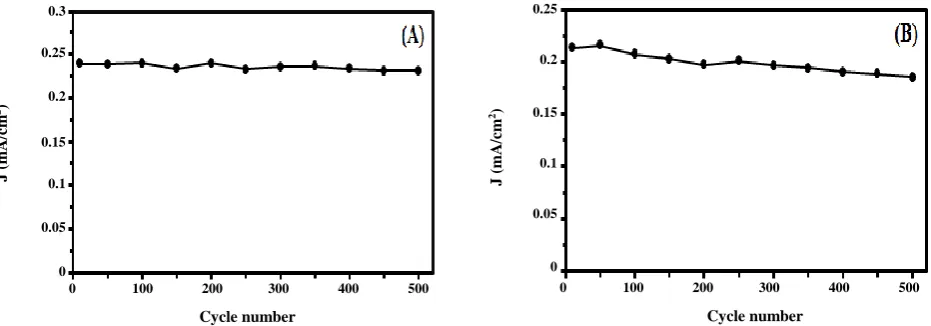
Lon-term stability and chronoamperometric study To determine the durability of Fe3O4@Pt/CCE
electrocatalyst, the forward anodic peak current density is investigated for 500 cycles of potential cycling. Multi-cycle CV was performed in 0.5 M H2SO4 + 0.2 M fuel
solution for examining the long-term stability and the resulted forward anodic peak current density was measured and shown in Fig. 9. It can be observed that during repeated scan cycles, the anodic peak current
density on the Fe3O4@Pt/CCE electrocatalyst exhibited
a gradual drop, which may be related to structural changes of the electrocatalyst surface and/or degradation of Pt particles on the surface. After 500 cycles, the anodic peak current density remains at 96.53 % of the 1th cycle (the best performing cycle) for formic acid and 86.96 % of the 1th cycle (the best performing cycle) for formaldehyde. It can be observed that Fe3O4@Pt/CCE electrocatalyst
exhibits much slow degradation. It is concluded that due to the presence of Fe3O4 cores, Fe3O4@Pt/CCE
electrocatalyst exhibits high long-term stability [47]. For more detail investigation of electrocatalytic activity of Fe3O4@Pt/CCE electrocatalyst,
chronoamperometry measurements were studied. Chronoamperometric experiments were widely applied to explore the catalytic stability and also to study the antipoisoning ability of the electrocatalysts [71, 72]. The chronoamperometric experiments were measured at 0.65 V and 0.60 V for formic acid and formaldehyde vs. SCE, respectively for 2000 s. Fig. 10 shows the chronoamperometric curves of the Fe3O4@Pt/CCE and
Pt/CCE electrocatalysts in 0.5 M H2SO4 containing 0.2 M
fuel. As observed, the current densities of formic acid and formaldehyde electrooxidation on Fe3O4@Pt/CCE and
Pt/CCE electrocatalysts drop quickly at the beginning, and then become relatively stable. The initial surge of current is due to a charging current. A gradual and slower decay of the current density with time during chronoamperometry measurements implies that the electrocatalyst has high anti-poisoning ability [73]. 0.05 0.15 0.25 0.35 0.45 0.55 0.65 .75 0.85 0.95
E (Vvs.SCE)
0.58
0.48
0.38
0.28
0.18
0.08
-0.02
J
(
mA
/c
m
2) 1.35
1.15
0.95
0.75
0.55
0.35
0.15
-0.05
J
(
mA
/c
m
2)
-0.2 0 0.2 0.4 0.6 0.8 1 1.2 1.4 1.6
Fig. 9:Long-term stability of the Fe3O4@Pt/CCE electrocatalyst in (A) 0.5 M H2SO4 + 0.2 M formic acid solution and
(B) 0.5 M H2SO4 + 0.2 M formaldehyde at scan rate of 50 mV/s.
Fig. 10:Chronoamperometric curves for the Fe3O4@Pt/CCE and Pt/CCE electrocatalysts in
(A) 0.5 M H2SO4 + 0.2 M formic acid solution (Polarization potential: 0.65 V) and (B) 0.5 M H2SO4 + 0.2 M
formaldehyde solution (Polarization potential: 0.60 V) for 2000 s.
Because, when the suitable fixed potential was applied to the working electrode, due to the continuous oxidation of fuel molecules on the electrode surface, poisoning products such as CO begin to accumulate at the electrocatalyst surface and lead to a decrease in the oxidation current density. But if the removing reaction of intermediates on the electrocatalyst has high kinetics (anti-poisoning ability), the kinetics of fuel oxidation kept up high and consequently a slower decay of the current density with time was obtained [74]. As can be seen in Fig. 10, during the whole procedure, the Fe3O4@Pt/CCE
electrocatalyst exhibited higher current density and lower rate of current density decay than Pt/CCE. These results
are in good agreement with voltammetric studies and indicate that the presence of Fe3O4 improves the tolerance
of Pt nanoparticles against the poisoning species such as CO and CO-like intermediates, thus improving the catalytic activity and the stability of Pt nanoparticles [47].
CONCLUSIONS
Fe3O4@Pt core-shell nanoparticles/carbon-ceramic
electrode (Fe3O4@Pt/CCE) was successfully prepared
using a facile, cost effective and efficient approach. The Fe3O4@Pt core-shell nanoparticles structure has been
demonstrated by several techniques including XRD, SEM, EDX, TEM and electrochemical methods.
0 100 200 300 400 500
Cycle number
0.25
0.2
0.15
0.1
0.05
0
J
(
mA
/c
m
2) 0.3
0.25
0.2
0.15
0.1
0.05
0
J
(
mA
/c
m
2)
0 100 200 300 400 500
Cycle number
0.3
0.25
0.2
0.15
0.1
0.05
0
J
(
mA
/c
m
2)
0 500 1000 1500 2000
Time (s)
0 500 1000 1500 2000
Time (s)
0.4
0.3
0.2
0.1
0
J
(
mA
/c
m
The electrooxidation of formic acid and formaldehyde was investigated on the Fe3O4@Pt/CCE electrocatalyst
using cyclic voltammetry and chronoamperometry techniques. The Fe3O4@Pt/CCE show higher
electrocatalytic activity and good stability compared to Pt-alone nanoparticles on the carbon-ceramic electrode (Pt/CCE). This suggests that there was an electronic effect and promising effect of the core-shell structure on the properties of the Fe3O4@Pt/CCE electrocatalyst.
Therefore, the Fe3O4@Pt nanostructure has obvious
structural advantages in phrases of unique electrocatalytic properties, easy and clean processing, and saving expensive metals, which propose their great potential for use in fuel cell technologies.
Acknowledgment
The authors gratefully acknowledge the Research Council of Azarbaijan Shahid Madani University for financial support.
Received : July 8, 2015 ; Accepted : Jan. 18, 2016
REFERENCES
[1] Serrano E., Rus G., García-Martínez J.,
Nanotechnology for Sustainable Energy, Renew. Sust. Energy Rev., 13: 2373-2384 (2009).
[2] Carrette L., Friedrich K. A., Stimming U., Fuel Cells: Principles, Types, Fuels, and Application, Chem. Phys. Chem., 4: 162-193 (2000).
[3] Lamy C., Belgsir E. M., Léger J. M., Electrocatalytic Oxidation of Aliphatic Alcohols: Application to the Direct Alcohol Fuel Cell (DAFC), J. Appl. Electrochem., 31: 799-809 (2001).
[4] Corti H. R., Gonzalez E. R., “Direct Alcohol Fuel Cells: Materials, Performance, Durability and Applications”, Springer (2014).
[5] Xiong L., Manthiram A., Nanostructured Pt–M/C (M= Fe and Co) Catalysts Prepared by a Microemulsion Method for Oxygen Reduction in
Proton Exchange Membrane Fuel Cells,
Electrochim. Acta, 50: 2323-2329 (2005).
[6] Hamidi P., Ojani R., Razmi H., Razavipanah I., High Catalytic Performance of Pt Nanoparticles via Support of Conducting Polymer for Electrooxidation of Methanol at Carbon Ceramic Electrode, J. Iran. Chem. Soc., 12: 667-676 (2015).
[7] Razavipanah I., Rounaghi Gh.H., Arbab Zavvar M.H.,
Electrochemical Preparation of Effective and Low Cost Catalyst for Electrooxidation of Ethanol, J. Iran. Chem. Soc., 10: 1279-1289 (2013).
[8] Habibi B., Mohammadyari S., Facile Synthesis of Pd Nanoparticles on Nano Carbon Supports and Their Application as an Electrocatalyst for Oxidation of Ethanol in Alkaline Media: The Effect of Support,
Int. J. Hydrogen Energy, 40: 10833-10846 (2015). [9] Habibi B., Delnavaz N., Pt-CeO2/Reduced Graphene
Oxide Nanocomposite for the Electrooxidation of Formic Acid and Formaldehyde. RSC Adv., 5: 73639-73650 (2015).
[10] Habibi B., Mohammadyari S., Palladium Nanoparticles/Nanostructured Carbon Black Composite on Carbon-Ceramic Electrode as an Electrocatalyst for Formic Acid Fuel Cells, J. Taiwan Inst. Chem. Ene., 58: 245-251 (2016). [11] Wen W., Li Ch., Li W., Tian Y., Carbon-Supported
Pd-Cr Electrocatalysts for the Electrooxidation of Formic Acid that Demonstrate High Activity and Stability, Electrochim. Acta, 109: 201-206(2013). [12] Habibi B., Delnavaz N., Carbon-Ceramic Supported
Bimetallic Pt-Ni Nanoparticles as an Electrocatalyst for Oxidation of Formic Acid, Int. J. Hydrogen Energy, 36: 9581-9590 (2011).
[13] Habibi B., Delnavaz N., Electrocatalytic Oxidation of Formic Acid and Formaldehyde on Platinum
Nanoparticles Decorated Carbon-Ceramic
Substrate, Int. J. Hydrogen Energy, 35: 8831-8840 (2010).
[14] Raoof J.B., Hosseini S.R., Ojani R., Aghajani S.,
Fabrication of Bimetallic Cu/Pd Particles Modified Carbon Nanotube Paste Electrode and Its Use Towards Formaldehyde Electrooxidation, J. Mol. Liq., 204: 106-111 (2015).
[15] Yu Y., Su W., Yuan M., Fu Y., Hu J.,
Electrocatalytic Oxidation of Formaldehyde on Nickel Ion Implanted-Modified Indium Tin Oxide Electrode, J. Power Sources, 286: 130-135 (2015).
[16] Lei T., Zhang Sh., Li D., Zhang W., huang Sh., Xie Ch.,
The Influence of Au and Pt Electrodes on the Stability of TiO2 under UV Light Activation for
Sensing Formaldehyde in Moisture Circumstances.
[17] Jianga C., Chena H., Yua C., Zhanga S., Liua B., Kong J., Preparation of the Pt Nanoparticles Decorated Poly(N acetylaniline)/MWNTs Nanocomposite and Its Eelectrocatalytic Oxidation Toward Formaldehyde,
Electrochim. Acta, 54: 1134-1140 (2009).
[18] Raoof J.B., Ojani R., Abdi S., Hosseini S.R., Highly Improved Electrooxidation of Formaldehyde on Nickel/poly (o toluidine)/Triton X-100 Film Modified Carbon Nanotube Paste Electrode, Int. J. Hydrogen Energy, 37: 2137-2146 (2012).
[19] Colussi S., Boaro M., Rogatis L., Pappacena A., Leitenburg C., Llorca J., Trovarelli. A, Room Temperature Oxidation of Formaldehyde on Pt-Based Catalysts: A Comparison between Ceria and Other Supports (TiO2, Al2O3 and ZrO2). Catal. Today, 253:
163-171 (2015).
[20] Gamelas J.A.F., Oliveira F., Evtyugina M.G., Portugal I., Evtuguin D.V., Catalytic Oxidation of Formaldehyde by Ruthenium Multisubstituted Tungstosilicic Polyoxometalate Supported on Cellulose/Silica Hybrid, Appl. Catal., A, 509: 8-16 (2016).
[21] QuZh., Chen D., Sun Y., Wang Y., High Catalytic Activity for Formaldehyde Oxidation of AgCo/APTES@MCM-41 Prepared by Two Steps Method, Appl. Catal., A, 487: 100-109 (2014). [22] Wang D., Wang J., Lu Sh., Jiang S.P., Facile
Synthesis of Sub-Monolayer Sn, Ru, and RuSn Decorated Pt/Nanoparticles for Formaldehyde Electrooxidation, J. Electroanal. Chem., 712: 55-61 (2014).
[23] Raoof J.B., Hosseini S. R., Rezaee Sh., Preparation o Pt/poly(2-Methoxyaniline)-sodium Dodecyl Sulfate Composite and Its Application for Electrocatalytic Oxidation of Methanol and Formaldehyde,
Electrochim.Acta, 141: 340-348 (2014).
[24] Yu Y., Wang T., Fu Y., Su W., Hu J., Platinum Nanoparticles Ion Implanted-Modified Indium Tin Oxide Electrode for Electrocatalytic Oxidation of Formaldehyde, Int. J. Hydrogen Energy, 39: 17617-17621 (2014).
[25] Habibi B., Pournaghi-Azar M.H., Composite Electrodes Consisting Pt Nano-Particles and Poly (aminophenols) Film on Pre-treated Aluminum Substrate as Electrocatalysts for Methanol Oxidation,
J. Solid State Electrochem., 14: 599-613 (2010).
[26] Habibi B., Pournaghi-Azar M.H., Abdolmohammad-Zadeh H., Razmi H., Electrocatalytic Oxidation of Methanol on Mono and Bimetallic Composite Films: Pt and Pt–M (M=Ru, Ir and Sn) Nano-particles in Poly(o-aminophenol), Int. J. Hydrogen Energy, 34: 2880-2892 (2009).
[27] Antolini E., Formation of Carbon-Supported PtM Alloys for Low Temperature Fuel Cells: A Review,
Mater. Chem. Phy., 78: 563-573 (2003).
[28] Ghosh Chaudhuri R., Paria S., Core/Shell Nanoparticles: Classes, Properties, Synthesis Mechanisms, Characterization, and Applications.
Chem. Rev., 112: 2373-2433 (2012).
[29] Sieben J.M., Alvarez A.E., Comignani V., Duarte M.M.E., Methanol and Ethanol Oxidation on Carbon Supported Nanostructured Cu Core Pt-Pd Shell Electrocatalysts Synthesized via Redox Displacement,
Int. J. Hydrogen Energy, 39: 11547-11556 (2014). [30] Otoufi M.K., Shahtahsebebi N., Kompany A.,
Goharshadi E., A Systematic Growth of Gold Nanoseeds on Silica for Silica@Gold Core-Shell Nanoparticles and Investigation of Optical Properties,
Int. J. Nano Dimension, 5: 525-531 (2014).
[31] Gelali A., Solymani SH., Elahi M., Ghodseahi T., Zahrabi H., Vesaghi M. A., Ahmadi Rad M., Shafiekhani A., Ahmadpourian A., Fabrication of Cu-Ni Core-Shell Nanoparticles by CO Deposition of RF-PECVD and RF-Sputtering, Iran. J. Surf. Engineering, 11: 39-43 (2011).
[32] Zhong C. J., Maye M.M., Core–Shell Assembled Nanoparticles as Catalysts. Adv. Mater., 13: 1507-1511 (2001).
[33] Yang H., Platinum-Based Electrocatalysts with Core-Shell Nanostructures. Angew. Chem. Int. Ed., 50: 2674-2676 (2011).
[34] Long N.V., Hien T.D., Asaka T., Ohtaki M., Nogami M.,
Synthesis and Characterization of Pt-Pd Nanoparticles with Core-Shell Morphology: Nucleation and Overgrowth of the Pd Shells on the As-Prepared and Defined Pt Seeds, J. Alloys Compd., 509: 7702-7709 (2011).
[36] Luo J., Wang L., Mott D., Njoki P. N., Lin Y., He T., Xu Z., Wanjana B. N., Lim I. I. S., Zhong C. J.,
Core/Shell Nanoparticles as Electrocatalysts for Fuel Cell Reactions, Adv. Mater., 20: 4342-4347 (2008).
[37] Sánchez-Padilla N.M., Montemayor S.M., Torres L.A., Rodríguez Varela F.J., Fast Synthesis and Electrocatalytic Activity of M@Pt(M [ Ru, Fe3O4, Pd)
Core-Shell Nanostructures for the Oxidation of Ethanol and Methanol, Int. J. Hydrogen Energy, 38: 12681-12688 (2013).
[38] Habibi B., Dadashpour E., Carbon-Ceramic Supported Bimetallic Pt-Ni Nanoparticles as an Electrocatalyst for Electrooxidation of Methanol and Ethanol in Acidic Media,Int. J. Hydrogen Energy, 38: 5425-5434 (2013).
[39] Habibi B., Dadashpour E., Electrooxidation of 2-Propanol and 2-Butanol on the Pt–Ni Alloy Nanoparticles in Acidic Media, Electrochim. Acta, 88: 157-164 (2013).
[40] Sánchez-Padilla N.M., Acosta D., Morales-Acosta M.D., Montemayor S. M., Rodríguez-Varela F.J.,
Catalytic Activity and Selectivity for the ORR of Rapidly Synthesized M@Pt (M [ Pd, Fe3O4, Ru)
Core-Shell Nanostructures, Int. J. Hydrogen Energy, 39: 16706-16714 (2014).
[41] Li Z., He Ch., Cai M., Kang Sh., A Shen P.K.,
Strategy for Easy Synthesis of Carbon Supported Co@Pt Core-Shell Configuration as Highly Active Catalyst for Oxygen Reduction Reaction, Int. J. Hydrogen Energy, 37: 14152-14160 (2012).
[42] Zhang M., Yan Z., Xie J., Core/shell Ni@Pd Nanoparticles Supported on MWCNTs at Improved Electrocatalytic Performance for Alcohol Oxidation in Alkaline Media, Electrochim. Acta, 77: 237-243 (2012).
[43] Padayachee D., Golovko V., Marshall A. T., The Effec of MnO2 Loadin on the Glycerol
Electrooxidation Activi of Au/MnO2/C Catalysts,
Electrochim. Acta, 98: 208-217 (2013).
[44] Yan Z., Meng H., Kang Shen P., Meng Y., Ji H.,
Effect of the Templates on the Synthesis of Hollow Carbon Materials as Electrocatalyst Supports for Direct Alcohol Fuel Cells, Int. J. Hydrogen Energy, 37: 4728-4736 (2012).
[45] Trasatti S., Petrii O.A., Real Surface Area Measurements in Electrochemistry, Pure Appl. Chem., 63: 711-734 (1991).
[46] ChaparroA.M., Martín A.J., Folgado M.A., Gallardo B., Daza L., Comparative Analysis of the Electroactive Area of Pt/C PEMFC Electrodes in Liquid and Solid Polymer Contact by Underpotential Hydrogen Adsorption/Desorption, Int. J. Hydrogen Energy, 34: 4838-4846 (2009).
[47] Camachoa B.R., Moraisa C., Valenzuela M.A., Alonso-Vantea N., Enhancing Oxygen Reduction Reaction Activity and Stability of Platinum via Oxide-Carbon Composites, Catal. Today, 202: 36-43 (2013). [48] Rezaei B., Havakeshian E., Ensafi A.A., Fabrication
of a Porous Pd Film on Nanoporous Stainless Steel Using Galvanic Replacement as a Novel Electrocatalyst/Electrode Design for Glycerol Oxidation, Electrochim. Acta, 136: 89-96 (2014). [49] Zhang M., Yan Z., Xie J., Core/shell Ni@Pd
Nanoparticles Supported on MWCNTs at Improved Electrocatalytic Performance for Alcohol Oxidation in Alkaline Media, Electrochim. Acta, 77: 237-243 (2012).
[50] Xu W., Zhua Sh., Li Zh., Cui Zh., Yang X.,
Synthesis and Catalytic Properties of Pd Nanoparticles Loaded Nanoporous TiO2 Material,
Electrochim. Acta, 114: 35-41 (2013).
[51] Qin Y.H., Yang H.H., Lva R.L., Wang W.G., Wang C.W., TiO2 Nanotube Arrays Supported Pd
Nanoparticles for Ethanol Electrooxidation in Alkaline Media, Electrochim. Acta, 105: 372-277 (2013). [52] Zhu J., Zhao X., Xiao M., Liang L., Liu Ch., Liao J.,
Xing W., The Construction of Nitrogen-Doped Graphitized, Carbon-TiO2 Composite to Improve the
Electrocatalyst for Methanol Oxidation, Carbon, 72: 114-124 (2014).
[53] Liang R., Hu A., Persic J., Zhou Y.N., Palladium Nanoparticles Loaded on Carbon Modified TiO2
Nanobelts for Enhanced Methanol Electrooxidation,
Nano-Micro Lett, 5: 202-212 (2013).
[55] Santiago E.I., Varanda L.C., Villullas M.J., Carbon-Supported Pt-Co Catalyst Prepared by a Modified Polyol Process as Cathodes for PEM Fuel Cells,
J. Phys. Chem. C, 111: 3146-3151 (2007).
[56] Wu G., Swaidan R., Cui G., Electrooxidations of Ethanol, Acetaldehyde and Acetic Acid Using PtRuSn/C Catalysts Prepared by Modified Alcohol-Reduction Process, J. Power Sources, 172: 180-188 (2007).
[57] Wanga X., Maa G., Zhua F., Lina N., Tanga B., Zhang Zh., Preparation and Characterization of Micro-arc-induced Pd/TM(TM = Ni, Co and Ti) Catalysts and Comparison of Their Electrocatalytic Activities Toward Ethanol Oxidation, Electrochim. Acta, 114: 500-508 (2013).
[58] Zhou W., Lee J.Y., Highly Active Core-Shell Au@Pd Catalyst for Formic Acid Electrooxidation,
Electrochem. Commun., 9: 1725-1729 (2007). [59] Ma C., Jin Y., Shi M., Chu Y., Xu Y., Jia W., Yuan Q.,
Chen J., Pan H., Dai Q., Highly Active Pd/WO3
-CNTs Catalysts for Formic Acid Electrooxidation and Study of the Kinetics, Ionics, 20: 1419-1426 (2014). [60] Wang Y., Wu B., Gao Y., Tang Y., Lu T., Xing W.,
Liu C., Kinetic Study of Formic Acid Oxidation on Carbon Supported Pd Electrocatalyst, J. Power Sources, 192: 372-375 (2009).
[61] Lović J.D., Tripković A.V., Gojković S. Lj., Popović K. Dj., Tripković D.V., Olszewski P., Kowal A., Kinetic Study of Formic Acid Oxidation on Carbon-Supported Platinum Electrocatalyst, J. Electroanal. Chem., 581: 294-302 (2005).
[62] Jovanović V.M., Tripković D., Tripković A., Kowal A., Stoch J., Oxidation of Formic Acid on Platinum Electrodeposited on Polished and Oxidized Glassy Carbon, Electrochem. Commun., 7: 1039-1044 (2005).
[63] Liu Y., Wang L., Wang G., Deng C., Wu B., Gao Y.,
High Active Carbon Supported PdAu Catalyst for Formic Acid Electrooxidation and Study of the Kinetics. J. Phys. Chem. C. 114: 21417-21422 (2010).
[64] Habibi E., Razmi H., Glycerol Electrooxidation on Pd, Pt and Au Nanoparticles Supported on Carbon Ceramic Electrode in Alkaline Media, Int. J. Hydrogen Energy, 37: 16800-16809 (2012).
[65] Rezaei M., Tabaian S. H., Fatmehsari Haghshenas D.,
The Role of Electrodeposited Pd Catalyst Loading on the Mechanisms of Formic Acid Electro-Oxidation. Electrocatalysis, 5: 193-203 (2014). [66] Lu H.T., Yang Z.J., Yang X., Fan Y., CeO2
Nanotubes Supported Pd Electrocatalysts for Formic Acid Oxidation. Electrocatalysis, 6: 255-262 (2015). [67] Khorasani-Motlagh M., Noroozifar M., Ekrami-Kakhki M. S., Investigation of the Nanometals (Ni and Sn) in Platinum Binary and Ternary Electrocatalysts for Methanol Electrooxidation, Int. J. Hydrogen Energy, 36: 11554-11563 (2011). [68] ÓSullivan E. J. M., White J. R., Electro‐Oxidation of
Formaldehyde on Thermally Prepared RuO2 and
Other Noble Metal Oxides. J. Electrochem. Soc., 136: 2576-2583 (1989).
[69] Brett C.M.A., Brett M.O., “Electrochemistry: Principles, Methods, and Applications”, Oxford University Press, Oxford, (2002).
[70] Ojani R., Safshekan S., Raoof J.B., Silver Nanoparticle Decorated Poly(2-aminodiphenylamine) Modified Carbon Paste Electrode as a Simple and Efficient Electrocatalyst for Oxidation of Formaldehyde, Chin. J. Catal., 35: 1565-1570 (2014).
[71] Wen W., Li Ch., Li W., Tian Y., Carbon-Supported Pd-Cr Electrocatalysts for the Electrooxidation of Formic Acid that Demonstrate High Activity and Stability, Electrochim.Acta, 109: 201-206 (2013). [72] Kakati N., Maiti J., Lee S.H., Yoon Y.S., Core Shell
Like Behavior of PdMo Nanoparticles on Multiwall Carbon Nanotubes and Their Methanol Oxidation Activity in Alkaline Medium, Int. J. Hydrogen Energy, 37: 19055-19064 (2012).
[73] Tan H., Ma X., Sheng L., An K., Yu L., Zhao H., Xu J., Ren W., Zhao X., Direct Synthesis of Few-Layer Graphene Supported Platinum Nanocatalyst for Methanol Oxidation, Jap. J. Appl. Phys, 11: 117101 (2014).
[74] Zhang Q., Pan D., Zhang H. Y., Han H.T.,