ORIGINAL ARTICLE
Performance Analysis and Improvement
of Flat Torque Converters Using DOE Method
Guang‑Qiang Wu
1,2*, Jie Chen
1and Wen‑Jie Zhu
1Abstract
Automotive torque converters have recently been designed with an increasingly narrower profile for the purpose of achieving a smaller axial size and reducing weight. Design of experiment (DOE) and computational fluid dynam‑ ics (CFD) techniques are applied to improve the performance of a flat torque converter. Four torque converters with different flatness ratios (0.204, 0.186, 0.172, and 0.158) are designed and simulated first to investigate the effects of flatness ratio on their overall performance, including efficiency, torque ratio, and impeller torque factor. The simulation results show that the overall performance tends to deteriorate as the flatness ratio decreases. Then a parametric study covering six geometric parameters, namely, inlet and outlet angles of impeller, turbine, and stator is carried out. The results demonstrate that the inlet and outlet angles play an important role in determining the performance charac‑ teristics of a torque converter. Furthermore, the relative importance of the six design parameters is investigated using DOE method for each response (stall torque ratio and peak efficiency). The turbine outlet angle is found to exert the greatest influence on both responses. After DOE analysis, an optimized design for the flat torque converter geometry is obtained. Compared to the conventional product, the width of the optimized flat torque converter torus is reduced by about 20% while the values of stall torque ratio and peak efficiency are only decreased by 0.4% and 1.7%, respec‑ tively. The proposed new optimization strategy based on DOE method together with desirability function approach can be used for performance enhancement in the design process of flat torque converters.
Keywords: Torque converter, Flatness ratio, Computational fluid dynamics (CFD), Parametric study, Design of experiment (DOE)
© The Author(s) 2018. This article is distributed under the terms of the Creative Commons Attribution 4.0 International License (http://creat iveco mmons .org/licen ses/by/4.0/), which permits unrestricted use, distribution, and reproduction in any medium, provided you give appropriate credit to the original author(s) and the source, provide a link to the Creative Commons license, and indicate if changes were made.
1 Introduction
Torque converters are an important part of automatic transmissions in automobiles and other vehicles. It pro-vides automatic torque amplification according to the different rotational speed between the input and output speeds without any active control, inherently suppressing engine torque fluctuations. Because it significantly affects the fuel economy, launch feeling and drivability, interests in the development of a high efficiency and performance have been increased recently.
In recent years, with the development of computer technology, computational fluid dynamics (CFD) has been widely used in hydraulic machine design and opti-mization. Zhao et al. [1] optimized a double-channel
pump’s impeller by combined using of CFD, multi-objective genetic algorithm (MOGA) and artificial neu-ral networks (ANN). Li et al. [2] carried out an entropy production analysis to investigate the hump characteris-tics of a pump turbine based on CFD simulations. Sho-jaeefard et al. [3], Tan et al. [4] studied effects of some geometric parameters on fluid dynamic characteristics of a centrifugal pump by CFD. Many researchers have also studied the flows in torque converters by using CFD codes employing various methods [5, 6]. Since a number of variables are involved in the design of a torque con-verter, it is very difficult to achieve an optimal design. In order to improve the converter performance, it is required to obtain detailed understanding and relation-ship between the governing parameter and its effect on the performance, including efficiency, torque ratio and impeller torque factor. Kubo et al. [7] described the rela-tionship between the design parameters used to define
Open Access
*Correspondence: [email protected]
the geometry of an automotive torque converter and the resultant efficiency in relation to the internal flow charac-teristics. Shin et al. [8, 9] investigated the effect of reac-tor blade geometry with varying thickness ratios, scroll angles and slot angles on the performance of a torque converter. Song et al. [10] presented an integrated design process TDOS (Torque converter Design Optimization System) including torque converter geometry designer, 3D CFD analysis module, and design optimizer. The sys-tem was used to investigate the effect of design param-eters on the performance.
Most passenger cars with small and medium size engines have adopted a front-wheel-drive layout in recent years. Torque converters accordingly have been designed with an increasingly narrower profile for the purpose of achieving a smaller axial size and reducing weight. A number of researchers have studied the flat torque con-verter employing both analytical and experimental meth-ods. Ejiri et al. [11] manufactured and tested four torque converters with different flatness ratios. The experimen-tal results show that the overall performance deteriorates when the flatness ratio is reduced to less than about 0.2. Kim et al. [12] investigated effects of the stator with two different shapes suitable for an axially squashed torus on hydraulic performance variation. Ochi et al. [13], Kietlinski et al. [14], and Usui et al. [15] developed new super-flat torque converters to provide free space for new equipments without much depreciation of efficiency. Abe et al. [16] employed newly developed stator blades to develop the fluid flow channels for a thin type torque converter with a flattening ratio of 50%, while maintain-ing torque converter performance. Yan et al. [17] pro-posed a flexible flat torque converter and estimated the influence of the flatness ratio on performance. Liu et al. [18] investigated the internal flow characteristics of the flat torque converter based on elliptical design path. However, there are no reports regarding combination effect of the blade geometry including inlet and outlet angles of impeller, turbine, and stator on the flat torque converter performance characteristics.
DOE method is widely used to find the importance level of the design parameters with respect to the optimi-zation target and obtain the best combination of design variables. Park et al. [19] studied a methane-fueled gas engine generator with addition of hydrogen using DOE method. Hatami et al. [20] applied central compos-ite design based on DOE to obtain an optimal design of the vane geometry for a variable geometry turbine. Taghavifar et al. [21] applied DOE evaluation to intro-duce the optimum injection strategy-chamber geometry of diesel engine. However, there have been relatively few applications of DOE method to flat torque converters optimization.
In this paper, the main objective is to improve the over-all performance of a flat torque converter by using DOE method and CFD calculations. Firstly, performance char-acteristics of four torque converters with different flat-ness ratios are investigated. Then, the sensitivity analysis is used to analyze the influence of inlet and outlet angles of impeller, turbine, and stator on the performance of a flat torque converter. Finally, the optimization analy-sis is performed by using DOE post-processing analyanaly-sis together with desirability function approach.
2 Flat Torque Converter Design 2.1 Torus Design
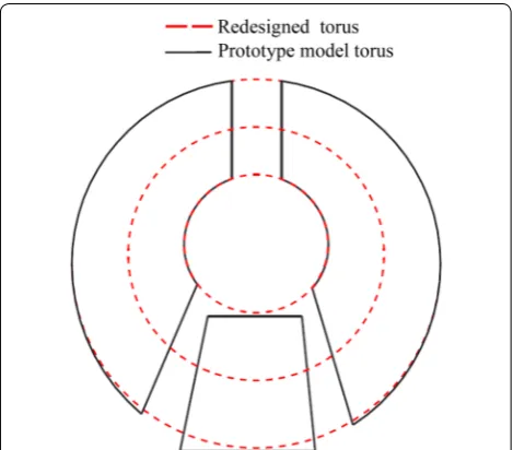
The flat torque converter design started with the defini-tion of the torus shape. A torque converter with 250 mm nominal diameter was chosen as the prototype model. Elliptical design method was used to redesign the mean streamline of the torque converter and flatness ratio was redefined as the rate of major axis and minor axis. The redefined flatness ratio is represented by the symbol e in this paper. Given the flow area in the circular path, in the proposed torque converter model, was assumed con-stant, the shell and the core shapes were also redesigned. The torus design result compared with prototype model torus is shown in Figure 1.
As shown in Figure 1, the redesigned torus shows good agreement with the prototype model torus so that it could be used to design flat torque converters. Four torque con-verters with different flatness ratios were designed and referred to here as type 1 to type 4, in decreasing order of flatness ratio, as shown in Table 1.
Figure 1 Comparison of redesigned torus with prototype model
Figure 2 illustrates the approach to shorten the axial dimension of the fluid flow channel. The torus could be flattened without changing the inlet radius R1 , and outlet radius R2 of each blade element. The design parameters were unchanged as much as possible except the flatness ratio and the stator axial length was pro-portional to the torque converter axial length. In this present paper, four types of torus with different flatness ratio are designed using the same method.
2.2 Blade Design
The impeller and turbine blades were designed to match the flat torus without changing in their inlet and outlet angles on the design path, a curve that bisects the flow passage cross-sectional area. The impeller had 31 blades and the turbine had 29 blades, which all had the thickness of 1.0 mm. The blades of four different stators all had the same distribution of thickness, it fea-tures relatively thick profile, which was better hydraulic performance than thin blades. They were also identical to each other inlet and outlet angle except for shapes. The inlet and outlet angles on the design path for the three elements are shown in Table 2.
3 Flat Torque Converter Design 3.1 Computational Method
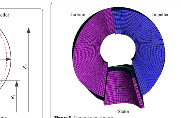
To represent the complex geometry of a torque converter and generate the computational mesh in an appropriate way, ICEM and Pro/Engineer respectively, were used. The computational mesh is given in Figure 3 where one blade passage is shown for each element to illustrate the mesh distribution in the computational field when about 81,000 grid cells in total were used. The leakage between the elements and also between an element and the core flow were disregarded. A cyclic boundary condi-tion was imposed on both peripheral boundaries outside a blade passage. A no-slip wall boundary condition was also imposed on all the walls bounding the domain, with a spin applied as necessary. The interfaces between ele-ments have been handled by using the explicit multiple reference frame (MRF) method which allows the prob-lem to be solved in a different rotating reference, instead of a transient moving mesh. The inherent advantage of the MRF approach was the ability to build the computa-tional mesh of each of the rotating components indepen-dently. A second-order upwind differencing scheme was utilized and the standard k-ε model was also used for the turbulence. Steady state simulations were performed for a range of speed ratios from 0.0 to 0.9 while maintaining an impeller speed of 2000 r/min.
Table 1 Parameters of torus with different flatness ratios Parameters Type 1 Type 2 Type 3 Type 4
Nominal diameter D (mm) 250 250 250 250
Width of torus W (mm) 51 46.40 42.95 39.53
Flatness ratio e0 0.204 0.186 0.172 0.158
Redefined flatness ratio e 1.0 0.9 0.8 0.7
Figure 2 Approach to decrease axial length of torus
Table 2 Inlet and outlet angles of three elements
Parameters Impeller Turbine Stator
Inlet angle β1 (°) 131 34 97.5
Outlet angle β2 (°) 50 144 21
3.2 Results and Discussion
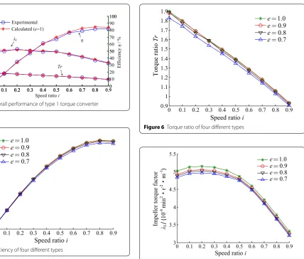
Four torque converters with different flatness ratio were calculated using a CFD code in order to evaluate the change in their overall performance, including efficiency η , torque ratio Tr and impeller torque factor I . The accu-racy of the evaluation results was highly dependent on the accuracy of the CFD results. Therefore, it was impor-tant to obtain reliable CFD results. Figure 4 compares the measured and calculated overall performance for the type 1 torque converter. As indicated here, the tendencies of the experimental data correlated relatively well with the calculated results, confirming that the computational method is valid in general.
Figure 5 shows the overall efficiencies calculated for all four types of torque converters. As the flatness ratio e decreases, the overall efficiency decreases, which is quite remarkable at high speed ratio. The main cause of this decline in overall efficiency was attributed to a greater loss within the fluid flow channels due to flattening. Fig-ure 6 describes the torque ratio Tr versus the speed ratio i with four types of torque converters. It is of note that the type 2 ( e=0.9 ) has nearly the same values with the
reference type ( e=1.0 ), and the other types show the lower torque ratio throughout the whole range of speed ratios. Figure 7 illustrates the impeller torque factor com-parison among the four types. Among the four types, the type 4 ( e=0.7 ) shows the lowest value of impeller torque factor I . When the flatness ratio e decreases, the mag-nitude of the impeller torque factor I tends to decrease especially at low speed ratio. Based on the results in Fig-ures 5, 6, 7, it is concluded that the overall performance tends to deteriorate as the flatness ratio e decreases.
4 Optimal Design of a Flat Torque Converter
The trend in future automatic-transmission designs is to achieve comparable performance to traditional designs but with reduced mass and in less space. The challenge in torque converter design is to develop a reduced-width torus without sacrificing performance. In this paper, CFD is used to analyze numerous iterations of torque convert-ers to optimize the torus for the allowed space. The type 4 torque converter with flatness ratio 0.158 ( e=0.7 ) was chosen as the study object.
0 0.1 0.2 0.3 0.4 0.5 0.6 0.7 0.8 0.9 0 1 2 3 4 5 6 7 8 9 10
0 0.1 0.2 0.3 0.4 0.5 0.6 0.7 0.8 0 50 100
0 0.1 0.2 0.3 0.4 0.5 0.6 0.7 0.8 0.90 10 20 30 40 50 60 70 80 90 100
Calculated (e=1)
Speed ratio i
Torque ratio
Tr
Impeller torque factor
λI
/ (
10
-6min
2gr
-2g m -1) Efficiency η / %
λI η
Tr Experimental
Figure 4 Overall performance of type 1 torque converter
0 0.1 0.2 0.3 0.4 0.5 0.6 0.7 0.8 0.9 0 10 20 30 40 50 60 70 80 90
Speed ratio i
Efficiency
η
/ % e 0.7
0.8
e 0.9 e 1.0 e
Figure 5 Efficiency of four different types
0 0.1 0.2 0.3 0.4 0.5 0.6 0.7 0.8 0.9 0.9 1 1.1 1.2 1.3 1.4 1.5 1.6 1.7 1.8 1.9
Speed ratio i
Torque ratio
Tr ee 0.70.8
0.9
e 1.0
e
Figure 6 Torque ratio of four different types
0 0.1 0.2 0.3 0.4 0.5 0.6 0.7 0.8 0.9 3 3.5 4 4.5 5 5.5
Speed ratio i
Impeller torque facto
r λI / ( 10 -6 mi n 2 g r -2 g m -1 ) 0.7 e 0.8 e 0.9 e 1.0 e
4.1 Sensitivity Analysis of Inlet and Outlet Angles
Since the blade transmits all of the torque of a torque converter, its design is of utmost importance. In fact, each of the blades would receive working fluid without shock, deflect the flow smoothly throughout the length of blade passage, and discharge the fluid at the optimum angle at all conditions of speed ratio and torque distribu-tion. Unfortunately, it is very difficult to meet optimal requirements. In the present study, a sensitivity analysis was used to investigate the effect of the blade geometric parameters on the torque converter performance charac-teristics. The main parameters investigated in this paper were inlet and outlet angles of the impeller, turbine, and stator. To improve the design efficiency, a software was developed for generating the blades with various inlet and outlet angles [22]. The blades of type 1 torque con-verter with inlet and outlet angles shown in Table 2 were chosen as the reference blades in order to compare the performances of the others. Finally, blades of the impel-ler, turbine, and stator with various inlet and outlet angles (5°, 10°, or 15° below and above the reference value of the parameter) were generated.
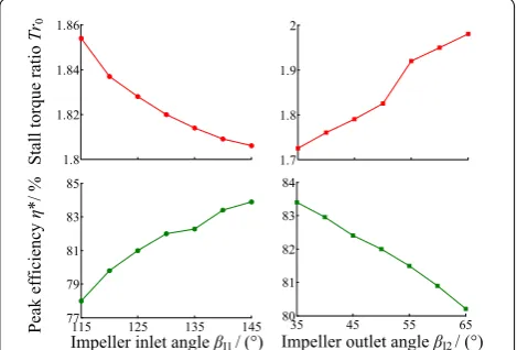
Torque converters with different blades were calcu-lated using the above-mentioned computational method in order to evaluate the effect of inlet and outlet angles on their overall performance, including peak efficiency η∗ and stall torque ratio Tr0 . Figure 8 shows the sensitivity of impeller inlet and outlet angles on the performance char-acteristics of the converter. The impeller inlet angle βI1 ranges from 115° to 145° while the outlet angle βI2 ranges from 35° to 65°. In the range of βI1 , performance Tr0 decreases with increase of angle, whereas η∗
increases. Conversely, the increase of βI2 causes increase of Tr0 and decrease of η∗
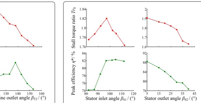
. Figure 9 provides the sensitivity of turbine inlet and outlet angles on the performance characteristics of the converter. The turbine inlet angle βT1 ranges from 20° to 55° while the outlet angle βT2 ranges from 120° to
155°. It is of note that the torque converter with reference blades shows the highest value of Tr0 among simulation cases with different βT1 and highest value of η∗ among
simulation cases with different βT2 . The simulation case
with βT1 five degree lower than the reference blade shows drastically decreases in η∗
. It is seen that Tr0 decreases with increase of βT2 . Figure 10 illustrates the
sensitiv-ity of stator inlet and outlet angles on the performance characteristics of the converter. The stator inlet angle βS1 ranges from 80° to 115° while the outlet angle βS2 ranges
from 5° to 40°. Similarly, the simulation case with refer-ence blades shows the highest Tr0 value among cases with different βS1 . Performance η∗ increases first and then decreases with increase of βS1 . It is found that both
per-formance Tr0 and η∗
decrease with increase of βS2.
Based on the results in Figures 8, 9, 10, it is concluded that the inlet and outlet angles of the impeller, turbine and stator play an important role in determining the per-formance characteristics of a torque converter including stall torque ratio and peak efficiency. The sensitivity anal-ysis provides useful information of the influence of design parameters individually on the flat torque converter, but not provides information on their combinations effect. Later, a DOE technique would be used to gauge the com-bination effect of these six dominant parameters.
4.2 DOE Method
Design of experiments (DOE) is a collection of math-ematical and statistical techniques to reduce the number of experiments in order to find the effect of parameters affecting a response in a process, thereby aiming for a reduction in both costs and time [23–25]. It is also useful to obtain a great deal of information through an action to reduce the number of simulations. The aim is to select some points that the numerical simulations should be investigated and can be adopted for planning, conduct-ing, analyzconduct-ing, and interpreting controlled tests in order to evaluate the factors that control the value of a param-eter or group of paramparam-eters. A DOE method sets out configurations (or arrangements) to be conducted using an appropriate orthogonal array; the terminology used in these arrays includes “factors”—an item that is to be varied during the simulations, “level”—the number of times a factor is to be varied during the simulations and “configuration number”—the number of simulations that are required to be run to complete the analysis [26]. For this paper six main geometrical parameters of a torque converter are selected as design variables (factors), which are the inlet and outlet angles mentioned above. For each design parameter, five different values (levels) were assigned. So 25 (L25[56]) configurations with differ-ent combinations were generated for DOE. The original values of the six parameters are listed in Table 2 and the
35 45 55 65
80 81 82 83 84 1.7 1.8 1.9 2
115 125 135 145
77 79 81 83 85 1.8 1.82 1.84 1.86
Impeller inlet angle βI1/(°)
Stall torque ratio
Tr0
Impeller outlet angle βI2/ (°)
Peak efficiency
η
*/
%
step values were chosen to be 3° for each factor. The final configurations for DOE can be constructed as shown in Table 3.
4.3 Numerical Simulation
The 25 cases with different blade dimensions were simu-lated using the above-mentioned method. Stall torque ratio and peak efficiency were selected as the dynamic characteristic and economic characteristic, respectively, to evaluate the performance characteristics of the flat torque converter. The simulation results are also pre-sented in Table 3. It can be seen that among the cases, numbers 14 and 19 have the two best results of stall torque ratio, and number 19 and 15 have the two best results of peak efficiency. It is clear that the maximum stall torque ratio and the maximum peak efficiency can not be obtained at the same time. So, an optimization study is needed to improve the overall performance of the flat torque converter.
4.4 DOE Post‑processing and Optimization
The processing of the data obtained from DOE could be described as below. Firstly, the 25 cases were grouped by the levels of a factor. Taking factor turbine inlet angle βT1
as example, five groups could be obtained and each of them had the same value (as shown in Table 3). The aver-age value of the stall torque ratio Tr0 of each group could be calculated as follows:
(1) K1=
1.7996+1.8055+1.8359+1.8055+1.7852
5
=1.80634,
(2) K2=
1.7621+1.7961+1.8014+1.8147+1.8199
5
=1.79884,
To be more clear, the influence levels K1 , K2 , K3 , K4 , and K5 were the average stall torque ratio when turbine inlet angle βT1 equaled 28°, 31°, 34°, 37°, and 40°, respectively.
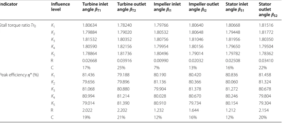
Then, the peak efficiency could be processed by the same method. In addition, range R was defined as the differ-ence between maximum and minimum values. Finally, the overall DOE analysis data was calculated and shown in Table 4.
The range R reflects the influence level of each geo-metrical parameter on the hydrodynamic characteris-tics of a torque converter. The contribution value C was defined as the percentage of the R value of a specific fac-tor to the total R values of all the factors. A factor with larger R would have more influence on torque converter performance indicators, and was considered as an impor-tant factor during converter design. While factors with small range value R would be considered as less impor-tant factors during design procedure. It could be found in Table 4 that, parameters turbine outlet angle βT2 and
stator outlet angle βS2 are the two most important fac-tors. To be more precise, the descending sort of range R is βT2> βS2 > βT1> βS1> βI2> βI1 for stall torque ratio, and βT2> βS2> βT1> βI2> βI1> βS1 for peak efficiency. Therefore, more focuses are needed on the (3) K3=
1.7699+1.7996+1.8269+1.8455+1.8347
5
=1.81532,
(4) K4=1.7806
+1.7982+1.7717+1.8426+1.8364
5 =1.8059,
(5) K5=
1.7998+1.7516+1.7817+1.7995+1.8106
5
=1.78864,
120 130 140 150 160
79 80 81 82 83 1.65 1.75 1.85 1.95
20 30 40 50 60
74 76 78 80 82 84 1.74 1.76 1.78 1.8 1.82 1.84
Peak efficiency
η
*/
%
Turbine inlet angle βT1/(°)
Stall torque ratio
Tr0
Turbine outlet angle βT2/ (°)
Figure 9 Turbine inlet and outlet angles sensitivity analysis
1.6 1.7 1.8 1.9 2
5 15 25 35 45
76 80 84 88 92
80 90 100 110 120
74 76 78 80 82 84 1.76 1.78 1.8 1.82 1.84
Peak efficiency
η
*/
%
Stator inlet angle βS1/(°)
Stall torque ratio
Tr0
Stator outlet angle βS2/ (°)
Table 3 Configurations and simulation results in DOE
Case number Factors Responses
Turbine inlet angle βT1 (°)
Turbine outlet angle βT2 (°)
Impeller inlet angle βI1 (°)
Impeller outlet angle βI2 (°)
Stator inlet angle βS1 (°)
Stator outlet
angle βS2 (°) Stall torque ratio Tr0
Peak efficiency η∗ (%)
1 28 138 125 44 91.5 15 1.7996 80.96
2 28 141 128 47 94.5 18 1.8055 81.65
3 28 144 131 50 97.5 21 1.8359 82.98
4 28 147 134 53 100.5 24 1.8055 81.23
5 28 150 137 56 103.5 27 1.7852 80.36
6 31 138 128 50 100.5 27 1.7621 78.34
7 31 141 131 53 103.5 15 1.7961 79.17
8 31 144 134 56 91.5 18 1.8014 80.29
9 31 147 137 44 94.5 21 1.8147 80.37
10 31 150 125 47 97.5 24 1.8199 80.11
11 34 138 131 56 94.5 24 1.7699 77.19
12 34 141 134 44 97.5 27 1.7996 79.82
13 34 144 137 47 100.5 15 1.8269 82.36
14 34 147 125 50 103.5 18 1.8455 82.76
15 34 150 128 53 91.5 21 1.8347 83.21
16 37 138 134 47 103.5 21 1.7806 79.24
17 37 141 137 50 91.5 24 1.7982 81.25
18 37 144 125 53 94.5 27 1.7717 79.53
19 37 147 128 56 97.5 15 1.8426 83.24
20 37 150 131 44 100.5 18 1.8364 81.71
21 40 138 137 53 97.5 18 1.7998 80.21
22 40 141 125 56 100.5 21 1.7516 77.59
23 40 144 128 44 103.5 24 1.7817 79.24
24 40 147 131 47 91.5 27 1.7995 78.47
25 40 150 134 50 94.5 15 1.8106 81.56
Table 4 Overall DOE analysis data Indicator Influence
level Turbine inlet angle βT1
Turbine outlet angle βT2
Impeller inlet angle βI1
Impeller outlet angle βI2
Stator inlet angle βS1
Stator outlet angle βS2
Stall torque ratio Tr0 K1 1.80634 1.78240 1.79766 1.80640 1.80668 1.81516
K2 1.79884 1.79020 1.80532 1.80648 1.79448 1.81772
K3 1.81532 1.80352 1.80756 1.81046 1.81956 1.80350
K4 1.80590 1.82156 1.79954 1.80156 1.79650 1.79504
K5 1.78864 1.81736 1.80496 1.79014 1.79782 1.78362
R 0.02668 0.03916 0.00990 0.02032 0.02508 0.03410
C 17% 25% 7% 13% 16% 22%
Peak efficiency η∗ (%) K
1 81.436 79.188 80.190 80.420 80.836 81.458
K2 79.656 79.896 81.136 80.366 80.060 81.324
K3 81.068 80.880 79.904 81.378 81.272 80.678
K4 80.994 81.214 80.028 80.670 80.246 79.804
K5 79.014 81.390 80.910 79.734 80.154 79.304
R 2.022 2.202 1.232 1.644 1.212 2.154
optimization of turbine outlet angle and stator outlet angle in the design phase, in order to achieve better per-formance of the flat torque converter. It should be noted that the results may have some difference with the con-clusions studied before. This is possible caused by the level selection of design parameters. In the present study, the desirability function was used to carry out the opti-mization [27]. The optimization results depend on the response weights of stall torque ratio and peak efficiency. In this study, optimization analysis was performed pro-vided that the stall torque ratio and peak efficiency had the same response weight. The results show that case 19, that is, 37° for βT1 , 147° for βT2 , 128° for βI1 , 56° for
βI2 , 97.5° for βS1 , and 15° for βS2 , have the best overall performance of the flat torque converter. Compared to the conventional product ( e=1.0 ), the flat torque con-verter with flatness ratio 0.158 ( e=0.7 ) is developed that reduce the width of the torus by about 20%. The axial length of the optimal flat torque converter and its weight have been substantially reduced while the values of stall torque ratio and peak efficiency are only decreased by 0.4% and 1.7%, respectively.
5 Conclusions
1. DOE method based on CFD technique is applied to obtain an optimized design of a flat torque con-verter geometry. To this end, 25 cases with different inlet and outlet angles of impeller, turbine, and stator are designed, constructed and simulated. The main advantage of DOE is its ability to consider the com-bination effect of design parameters on performance, as it is not limited to traditional one-factor-at-a-time approach.
2. The analysis of the DOE array identified the domi-nant geometrical influences on the performance of the flat torque converter. In general, the turbine out-let angle and stator outout-let angle are the two strongest influences on the converter performance characteris-tics, including stall torque ratio and peak efficiency. 3. Based on the calculation results in DOE,
desirabil-ity function approach is employed to optimize the flat torque converter geometry. It should be noted that the maximum values of stall torque ratio and peak efficiency can not be obtained at the same time. Finally, the best design configuration is achieved at case 19, that is, 37° for turbine inlet angle, 147° for turbine outlet angle, 128° for impeller inlet angle, 56° for impeller outlet angle, 97.5° for stator inlet angle, and 15° for stator outlet angle. The optimiza-tion method first used in performance improvement of flat torque converters can provide fundamental guidelines for designers.
Authors’ Contributions
G‑QW and JC were in charge of the whole trial; JC wrote the manuscript; JC and W‑JZ assisted with sampling and laboratory analyses. All authors read and approved the final manuscript.
Author details
1 School of Automotive Studies, Tongji University, Shanghai 201804, China. 2 Institute of Industrial Science, The University of Tokyo, Tokyo 153‑8505, Japan. Authors’ Information
Guang‑Qiang Wu, born in 1965, is currently a professor and a PhD candi‑ date supervisor at School of Automotive Studies, Tongji University, China and
Institute of Industrial Science, the University of Tokyo, Japan. He received his PhD degree from Jilin University, China, in 1994. His main research interests include advanced design theory and method of the automobile.
Jie Chen, born in 1988, is currently a PhD candidate at School of Automo-tive Studies, Tongji University, China. His main research interests include flow simulation, modification and optimal design theory for the torque converter.
Wen‑Jie Zhu, born in 1989, is currently a master candidate at School of Automotive Studies, Tongji University, China. His research interests include flow simulation, modification and optimum design theory for the torque converter.
Competing Interests
The authors declare that they have no competing interests.
Funding
Supported by National Natural Science Foundation of China (Grant No. 51575393).
Publisher’s Note
Springer Nature remains neutral with regard to jurisdictional claims in pub‑ lished maps and institutional affiliations.
Received: 21 July 2016 Accepted: 2 August 2018
References
[1] B Zhao, Y Wang, H Chen, et al. Hydraulic optimization of a double‑chan‑ nel pump’s impeller based on multi‑objective genetic algorithm. Chinese Journal of Mechanical Engineering, 2015, 28(3): 634–640.
[2] D Li, R Gong, H Wang, et al. Entropy production analysis for hump characteristics of a pump turbine model. Chinese Journal of Mechanical Engineering, 2014: 1–10.
[3] M H Shojaeefard, M Tahani, M B Ehghaghi, et al. Numerical study of the effects of some geometric characteristics of a centrifugal pump impeller that pumps a viscous fluid. Computers & Fluids, 2012, 60: 61–70. [4] L Tan, B Zhu, S Cao, et al. Influence of blade wrap angle on centrifugal
pump performance by numerical and experimental study. Chinese Jour-nal of Mechanical Engineering, 2014, 27(1): 171–177.
[5] G Q Wu, P Yan. System for torque converter design and analysis based on CAD/CFD integrated platform. Chinese Journal of Mechanical Engineering, 2008, 21(4): 35–39.
[6] D Yu, V Korivi, P Attibele, et al. Torque converter CFD engineering Part I: torque ratio and K factor improvement through stator modifications.
SAE Transmission and Driveline Systems Symposium, Detroit, USA, March 4, 2002: 2002–01–0883.
[7] M Kubo, E Ejiri. A loss analysis design approach to improving torque con‑ verter performance. SAE Transmission and Driveline Systems Symposium, Detroit, USA, February 25, 1998: 981100.
[8] S Shin, K J Kim, D J Kim, et al. The effect of reactor blade geometry on the performance of an automotive torque converter. SAE Transmission and Driveline Systems Symposium, Detroit, USA, March 4, 2002: 2002–01–0885. [9] S Shin, B C Lee, J H Hong, et al. Performance improvement using a slotted
[10] K Song, K Kim, J Park, et al. Development of the integrated process for torque converter design and analysis. SAE Technical paper, Detroit, USA, April 15, 2008: 2008‑01‑0785.
[11] E Ejiri, M Kubo. Influence of the flatness ratio of an automotive torque converter on hydrodynamic performance. Journal of Fluids Engineering, 1999, 121(3): 614–620.
[12] G Kim, J Jang. Effects of stator shapes on hydraulic performances of an automotive torque converter with a squashed torus. SAE Transmission and Driveline Systems Symposium, Detroit, USA, March 4, 2002: 2002–01–0886. [13] T Ochi, H Takeichi, H Kimura, et al. Development of a super‑flat torque
converter for the new Toyota FWD 6‑speed automatic transaxle. SAE Transmission and Driveline Systems Symposium, Detroit, USA, March 4, 2006: 2006–01–0149.
[14] T Kietlinski, M Fingerman. 248 mm elliptical torque converter from daim‑ lerchrysler corporation. SAE Transmission and Driveline Systems Symposium, Detroit, USA, March 4, 2007: 2007–01–0241.
[15] T Usui, T Okaji, T Muramatsu, et al. Development of a compact ultra‑flat torque converter equipped with a high‑performance damper. SAE Inter-national Journal of Engines, Detroit, USA, April 22, 2015, 8(2015–01–1088): 1374–1378.
[16] H Abe, M Tsuruoka, A Muto, et al. Development of super ultra flat torque converter with multi plate lock‑up clutch. SAE International Journal of Engines, Detroit, USA, April 21, 2009, 2(2009–01–0141): 48–55. [17] Q D Yan, C Liu, W Wei. Numerical simulation of the flow field of a flat
torque converter. Journal of Beijing Institute of Technology, 2012, 21(3): 309–314.
[18] C B Liu, W X Ma, X L Zhu, et al. Design method of flat hydrodynamic torque converter for passenger car based on elliptic torus. Journal of Jilin University (Engineering and Technology Edition), 2010, 40(4): 1039–1043, 2010. (in Chinese)
[19] J Park, H Cha, S Song, et al. A numerical study of a methane‑fueled gas engine generator with addition of hydrogen using cycle simulation
and DOE method. International Journal of Hydrogen Energy, 2011, 36(8): 5153–5162.
[20] M Hatami, M C M Cuijpers, M D Boot. Experimental optimization of the vanes geometry for a variable geometry turbocharger (VGT) using a design of experiment (DoE) approach. Energy Conversion and Manage-ment, 2015, 106: 1057–1070.
[21] H Taghavifar, S Jafarmadar, H Taghavifar, et al. Application of DoE evalua‑ tion to introduce the optimum injection strategy‑chamber geometry of diesel engine using surrogate epsilon‑SVR. Applied Thermal Engineering, 2016, 106: 56–66.
[22] L J Wang, G J Wu, G Hwan. Design strategy for modification of torque converters based on variation law of blade angle. Journal of Tongji Univer-sity (Natural Science), 2011, 39(11):1673–1679. (in Chinese)
[23] M Hatami, M Jafaryar, D D Ganji, et al. Optimization of finned‑tube heat exchangers for diesel exhaust waste heat recovery using CFD and CCD techniques. International Communications in Heat and Mass Transfer, 2014, 57: 254–263.
[24] M Hatami, D D Ganji, M Gorji‑Bandpy. Experimental and thermodynami‑ cal analyses of the diesel exhaust vortex generator heat exchanger for optimizing its operating condition. Applied Thermal Engineering, 2015, 75: 580–591.
[25] M Hatami, D D Ganji, M Gorji‑Bandpy. Experimental and numerical analysis of the optimized finned‑tube heat exchanger for OM314 diesel exhaust energy recovery. Energy Conversion and Management, 2015, 97: 26–41.
[26] R Spence, J Amaral‑Teixeira. A CFD parametric study of geometrical vari‑ ations on the pressure pulsations and performance characteristics of a centrifugal pump. Computers & Fluids, 2009, 38(6): 1243–1257. [27] A Sagbas. Analysis and optimization of surface roughness in the ball