Flame Spread of Fuel Droplets along an Array at
Normal Gravity
Narayan P. Sapkal1
1
Department of Mechanical Design Engineering, Pukyong National University, South Korea
Abstract: Experimental investigations on flame spread along a droplet array have been conducted at 0.1 MPa ambient pressure for the fuel droplets under normal gravity. The liquid fuels used in the current experiment are diesel, kerosene and C-heavy oil. Flame spread rates were measured from direct images of flame spread detected by a camcorder for droplet diameter of 1.0 mm. Results show that, the limiting flame spread occur at specific droplet spacing because, under normal gravity natural convection induces the upward flow of hot gases into a plume above the burning droplets and limits the lateral transfer of the thermal boundary layer. As a result, flame spread might not occur further in normal gravity. As the droplet spacing becomes smaller, the flame spread rate increases due to enhanced vaporization and chemical reaction. Then it attains a maximum value at a specific spacing. A further decrease in droplet spacing causes the spread rate to decrease due to the cooling effect by the large latent heat of vaporization.
Keywords: Flame spread rate; droplet array; droplet spacing; droplet ignition; normal gravity
I. INTRODUCTION
A major portion of the energy produced in the world today comes from the burning of liquid hydrocarbon fuels in the form of droplets. Understanding the fundamental physical processes involved in droplet combustion is not only important in energy production but also in propulsion, in the mitigation of combustion generated pollution, and in the control of the fire hazards associated with handling liquid combustibles.
Flame spread phenomenon of a different fuel droplet array have been investigated by researchers [1-4]. Flame spread of linear droplet array is the simplest configuration to study flame spread mechanism among droplets of fuel spray. Therefore, fundamental research on flame spread of fuel droplet array is expected to provide basic but essential knowledge on flame propagation mechanism of fuel spray. Also, flame spread among fuel droplets would occur in formation process of group flame which surrounds multiple droplets. The knowledge about flame spread in liquid fuel sprays is of vital importance especially when considering flame stability in apparatus such as gas turbine combustors, diesel combustors, and oil burning burners. The flame spread in liquid fuel sprays greatly depends on very complicated aerodynamics, thermodynamic and chemical processes. The interaction between liquid droplets make the phenomenon exceedingly complex and highly unsteady. In this point of view, researches on flame spread in one-dimensional droplet arrays have provided valuables clues, through which one might enhance the understanding of initial combustion characteristics of real spray combustors [1-2]. There are many excellent reviews related to spray combustion [5-6] and interactive droplet vaporization and combustion [7-8]. As for the flame spread of a fuel droplet array some researchers [9-10] experimentally investigated the flame spread rates of a volatile fuel droplets (n-heptane, benzene and ethanol) and reported that the spread rates increase monotonically as the spacing between adjacent droplets becomes smaller.
It has been reported that flame spread time, which is dependent upon droplet spacing and size is well correlated to immersion depth as defined by Schlieren images [1]. It was shown that the ignition delay time of an unburnt droplet is much longer than the time required for the flame to propagate from the local ignition site over the unburnt droplet and thus this leads to a non-uniform flame spread rate along a droplet array [2]. The behavior of flame spread might be remarkably different with and without natural convection. In the absence of gravity, a spherical thermal boundary layer is transferred with time from burning droplet to unburnt one. Subsequently, some part of the gaseous mixture layers ignited and the flame propagates flammable mixture layers, so that the flame develops around the unburnt droplet. From the above literature review, previous researches have not addressed the behavior of flame spread rate at ambient pressure 0.1 MPa under normal gravity for hydrocarbon fuels such as diesel, kerosene or C-heavy oil. Under normal gravity, natural convection induces the upward flow of hot gases into a plume above the burning droplets and limits the lateral transfer of the thermal boundary layer. As a result, flame spread might not occur in normal gravity, though in microgravity flame spreads under the same conditions according to the previous researches [2].
II. EXPERIMENTAL APPARATUS AND METHOD
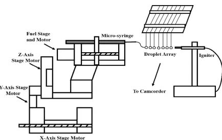
[image:3.612.83.565.75.327.2]Fig 1. Schematic diagram of experimental apparatus
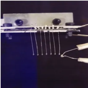
Fig 2. Schematic representation of droplet array generation system
[image:3.612.92.526.350.624.2]horizontal line in a droplet array. The suspenders are made of silica fiber with the diameter of 130 ± 5 μm and the end is of sphere with the diameter of 300 ± 25 μm for an easy attachment of fuel droplet. The suspender is bent twice for the delicate arrangement of droplet array on the jig. The fuel supply system consists of a micro-syringe of inner volume of 50 μl and a four-axis stage manipulator with a stepping motor of the high accuracy of ± 8.3 x 10⁻⁴μl. The fuels used are diesel, kerosene and C-heavy oil. The calibrated fuel supply to the suspenders is controlled by commands of computer software program with precedently detected positions. The shape of the suspended droplet is ellipsoidal and the equivalent droplet diameter is calibrated using the following formula [2,4].
D
(
D
12D
2)
1/3 (1)where D1 is the short diameter D2 is the long diameter
and the maximum measurement error of the supplied droplet diameter is ± 2.7 %.
A solenoidal electric igniter is made of Pt/Rh 13 % wire with the diameter of 0.3 mm. The igniter is charged by an electric current of 0.8 A for 0.7 sec to ignite the first droplet and then flame continues to spread to unburnt droplets. The flame spread rate is measured using camcorder camera system in such a way that, firstly direct images of flame spread were converted into a monochromatic image with a 1/60 s camcorder camera and images were enhanced by IMADJUST function of MATLAB. Then binary image was obtained by taking the threshold value (127 out of the intensity value of 0-255) using the image histogram. The position (X) of the value of the outermost edge of the image was defined as the tip of the flame, and the mean value of the rate of change of the flame tip over time was defined as the flame propagation speed (Sw) as below,
sw
dX
/
dt
(2)III.RESULTS AND DISCUSSIONS
[image:4.612.163.447.429.714.2]A. Droplet Array Ignition
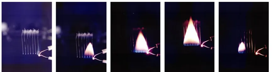
Fig 4. Flame propagation example with each droplet of 1 mm in diameter and 2.5 mm spacing between droplets
Initially, experiments were performed to make one dimensional droplet array. The suspender made from silica fiber were mounted on the jig as shown in the Figure 2 and 3. Since the suspenders undergoes ignition transition depending on the energy of the igniter, up to three droplet arrays from the igniter are under influence of the ignition transition. Therefore, seven suspenders are used to calculate the flame propagation speed for the remaining five liquid fuel droplets. If the droplet is attached to the suspender by maintaining the diameter of the suspender up to its end, the droplet will fall to the bottom. Therefore, to prevent this, the end of the suspender is heated by the lighter flame to heat the suspender tip and make the tip dissolve. Hence, suspender tip diameter could be increased and droplets were attached to the suspenders using micro-syringe connected with four-axis stage motor after detection of position for each suspender by computer program. Here, droplet size is calibrated by attaching a droplet to the first suspender as shown in Figure 3. If the stepper motor pushes the micro-syringe a certain amount of fuel, droplets will fall into the suspender according to the number of rotations of the stepper motor. After droplet formation, the suspended droplet diameter was measured from photograph using equation 1. Hence, the same calibrated size droplets were formed to all suspenders using four axis stage motor operated by program.
Afterwards, when the igniter drive switch is turned on, the ignition hot wire is heated for 0.7 sec and ignite the first droplet then ignition transition to the second droplet and normal flame propagation from the third droplet as shown in the Figure 4. Here, the distinction between flames is not clear because flame fronts are generated by blue light during the flame propagation. Therefore, we use the MATLAB code to define the flame front by image processing and finally flame spread rate was determined as discussed in previous section.
B. Flame Spread Rate Under Normal Gravity
Actually, the flame propagation speed (flame spread rate) is similar to the ignition delay time because a certain droplet ignites and shows the steady burning and the thermal wave propagates to the next droplet to ignite. Eventually, the flame propagation speed can be approximated by the sum of the evaporation time from the boiling of the droplet, the time it takes for the vaporized fuel gas to mix and the ignition delay time for the next droplet to ignite. Since the mixing time of the evaporated droplets is very short, the flame propagation speed is determined by the evaporation time of the droplet and the ignition delay time.
When the droplet spacing, S is larger than the flame diameter Df (S > Df) the adjacent droplet that is outside the flame is evaporated and the flame must propagate through the ignition. Therefore, a thermal wave from the flame causes conduction and radiation to heat the next droplet. As a result, flames propagate through adjacent droplets. Therefore, when the droplet spacing coincides with the radius of the flame, the flame propagation velocity becomes maximum and as the droplet spacing increases, the thermal wave propagates more time. As shown in previous results, when the flame propagation velocity decreases and the droplet gap increases excessively, there is limit droplet spacing in which the thermal wave reaches and the sufficient heat transfer could not be transferred to the adjacent droplet, thereby preventing the flame propagation from occurring.
When the droplet spacing, S is smaller than the flame diameter Df (S < Df) the adjacent droplet is present inside the flame. Therefore, as the droplet gap decreases, the amount of droplet to be evaporated increases. It means, as the droplet gap decreases, the heat capacity increases and the fuel evaporates due to heat transfer from the flame. This is because it takes more time to reach the ignition. Therefore, it is physically interpreted that the flame propagation rate decreases as the droplet gap decreases.
than the combustion life time of the burning droplet and the heat transfer from the burning droplet is not sufficient. In normal gravity, natural convection induces the upward flow of hot gases, so that the lateral transfer of the thermal boundary layer, formed around burning droplet, is limited. In Figure 5, as the droplet spacing decreases gradually, the unburnt droplet is exposed to the hot gas zone, so that the flame spread rate increases due to the enhanced vaporization and chemical reaction. It is then expected that the flame spread rate becomes maximum, provided that flammable mixtures near the unburnt droplet surface is exposed to the highest temperature gas zone. Therefore, the droplet spacing of the maximum flame spread rate is closely
Fig 5. Flame propagation speed with droplet spacing for different liquid fuels
related to flame diameter. The decrease beyond that implies that the adjacent unburnt droplet approaches inside of flame zone and chemical reaction rate decreases due to the cooling effect by the latent heat of vaporization. The flame spread rate decreases since extremely small droplet spacing represents an approach to a droplet pool. It is consequently seen that the relative position of a flame within a droplet spacing affects the flame spread rate greatly.
In addition, from Figure 5 it was observed that, even though the tendency of flame spread rate with droplet spacing was similar for all liquid fuels, the value of flame spread rate for C-heavy oil was smaller compared to diesel and kerosene.
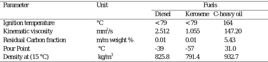
TABLEI LIQUID FUEL PROPERTIES
Parameter Unit Fuels
Diesel Kerosene C-heavy oil Ignition temperature °C < 79 < 79 164 Kinematic viscosity mm2/s 2.512 1.055 147.20 Residual Carbon fraction m/m weight % 0.01 0.01 5.43 Pour Point
Density at (15 °C)
°C
kg/m3 -39 825.8
-57 31.0 791.4 932.7
value compared to diesel and kerosene. In this manner flame spread rate behaviour with droplet spacing is elucidated for different liquid fuels.
IV.CONCLUSIONS
In this paper, flame spread experiments were performed for a liquid fuel droplet such as diesel, kerosene and C-heavy oil at 0.1 MPa ambient pressure and following findings were obtained:
A. Flame spread rate is dependent upon the relative position of flame to droplet spacing. That is, there exists a limit droplet spacing, above which flame does not spread. This limiting trend of flame spread rate occurred under the normal gravity. Due to normal gravity, natural convection induces the upward flow of hot gases, so that the lateral transfer of the thermal boundary layer, formed around burning droplet, is limited.
B. Flame spread rate increases with the decrease of droplet spacing since the unburnt droplet is exposed to hot gas zones. The maximum flame spread rate occurs at the droplet spacing, which corresponds to the flame diameter. The decrease beyond that leads to the decrease of flame spread rate due to the cooling effect of latent heat of vaporization.
V. ACKNOWLEDGMENT
This research is supported by the Department of Mechanical Design Engineering, Pukyong National University.
REFERENCES
[1] Reichenbach R., Squires D., Penner S.S, “Flame propagation in liquid fuel droplet arrays,” Proceedings of the 8th Symposium (International) on Combustion 1962; pp. 1068-1073.
[2] Brzustowski T.A., Sobiesiak A., Wojcicki S., “Flame propagation along an array of liquid fuel droplets at zero gravity”, Proceedings of the 8th Symposium (International) on Combustion 1981; pp. 265-273.
[3] Mikami M., Oyagi H., Kojima N., Kikuchi M., Wakashima Y., Yoda S., “Microgravity experiments on flame spread along fuel droplet arrays using a new droplet generation technique,” Combustion and Flame 2005; 141: pp. 241-252.
[4] Faeth, G.M., Olson, D.R., “The Ignition of hydrocarbon fuel droplets in air,” SAE Transactions 1968; 77: pp. 1793-1802. [5] Faeth, G.M., “Current status of droplet and liquid combustion,” Progress in Energy and Combustion Science 1977; 3: pp. 191-224. [6] Law, C.K., “Recent advances in droplet vaporization and combustion,” Progress in Energy and Combustion Science 1982; 8: pp. 171-201.
[7] Annamalai, K. and Ryan, W., “Interactive processes in gasification and combustion. Part I: Liquid drop arrays and clouds,” Progress in Energy and Combustion Science 1992; 18: pp. 221-295.
[8] Umemura, A., “Interactive droplet vaporization and combustion: Approach from asymptotics,” Progress in Energy and Combustion Science 1994; 20: pp. 325-372.
[9] Okajima, S., Kimoto, T., Abe, K. and Yamaguchi S., “Experimental study on flame propagation of fuel droplet array under a zero gravity condition,” Transactions of the Japan Society of Mechanical Engineers 1981; 47 (422 B): pp. 2058-2065.
[10] Yosida, S., Hara H., and Okajima, S., “Flame propagation in liquid fuel droplet arrays at elevated pressure under microgravity,” Transactions of the Japan Society of Mechanical Engineers 1989; 55 (512 B): pp. 1241-1247.