Fast Edge Detection Architecture using Different Levels
of Parallelism on a FPGA
Mohammad Shokrolah Shirazi
Electrical & Computer Engineering Department University of Nevada, Las Vegas
4505 South Maryland Parkway Las Vegas, NV, 89154
Brendan Tran Morris
Electrical & Computer Engineering Department University of Nevada, Las Vegas
4505 South Maryland Parkway Las Vegas, NV, 89154
ABSTRACT
Implementing edge detection techniques on a FPGA has recently become more popular since it benefits high speed which is de-sired for real-time applications. This work presents a fast FPGA-based architecture for first order derivative edge detection meth-ods. Fast pipeline-based architectures are presented which are able to perform edge detection using different levels of paral-lelism to accelerate the process. This acceleration includes ap-plying parallelism over convolution masks, edge detection mod-ules and image intensity values. Two different edge detection architectures are proposed called one-way and two-way paral-lel methods. The architectures are implemented using Verilog HDL for a typical image and we synthesized them for Cy-clone IV FPGA. Experimental results show the speed-up near to 460 and 920 for one-way and two-way parallel architectures.
General Terms:
Architecture, Real time applications, Speed-up
Keywords:
Edge detection, Parallelism, FPGA
1. INTRODUCTION
Nowadays, there is a new trend towards implementing image pro-cessing algorithms over a hardware rather than a software since it can more efficiently execute the algorithms [8]. As result, instead of general purpose processors that use software to run image pro-cessing algorithms, it is preferred to design a dedicated hardware for real-time image processing applications.
Some hardware approaches use Field Programmable Gate Array (FPGA) technology in their studies [2, 4, 8]. FPGA typically con-sists of a logic blocks’ matrices such as look up tables, gates, flip-flops and memories that are connected via programmable inter-connections. The FPGA configuration is generally specified using Hardware Description Languages (HDL) similar to Application-Specific Integrated Circuits (ASICs) which is custom manufactured for specific design tasks. FPGAs can be reprogrammed to form a desired application or functionality requirements after manufactur-ing. This feature distinguishes FPGAs from ASICs.
There are three major reasons that encourage researchers to imple-ment their algorithms on the FPGA. First, all logics inside FPGA can be rewired, or reconfigured with a different design according to the designers’ demand [14]. Second, the reconfigurable nature of FPGA allows us to implement different algorithms multiple times providing more flexibility in comparison with ASICs. Finally, the hardware nature of FPGA provides greater speed in comparison with software-based approaches since it uses different hardware modules that could be run in a parallel manner [3].
Edge detection is one of the popular image processing techniques that could be implemented on the FPGA. Image edges contain im-portant information for creating popular image features which con-tain significant structural properties used in computer vision for ob-ject recognition, tracking and motion detection [17].
Edge detection is the process of locating brightness discontinuities between pixels in a digital image. The basic edge detection meth-ods calculate the first order derivative by using some gradient op-erators such as Prewit [6, 10, 11], Sobel [1, 6, 11, 12, 15, 16, 18] or Robert [6]. In these methods, image gradients are obtained by in-troducing different kernel masks for performing convolution over the image. These masks are responsible for obtaining image gra-dients in two different directions. There are also some second or-der or-derivative methods such as Laplacian [17], Difference of Gaus-sian (DOG) [9] and Laplacian of GausGaus-sian [7]. These methods find zero crossing of the second derivative to determine edges. However, second derivative methods are not usually used for edge detection since they are too sensitive to noise [15].
In this paper, we present a fast FPGA-based architecture for first derivative edge detection by performing either Sobel or (and) Pre-wit or (and) Robert operation on a given image. Each Sobel, PrePre-wit or Sobel hardware modules benefit the pipeline structure running in parallel. The proposed edge detection architecture is fast due to some design related reasons. First, the entire image is located in-side FPGA memory [16, 18]. This allows access to several image pixel values in a single clock cycle which enables pipelining of the edge detection process. Second, parallelism is used for perform-ing horizontal and vertical convolutions simultaneously. Moreover, the Sobel, Prewit or Robert modules can be run simultaneously for generating multiple output images.
Sec-tion 6 provides experimental results and finally SecSec-tion 7 concludes the paper.
2. RELATED WORKS
As a new trend towards real-time image processing, some first or-der or-derivative edge detection methods have been implemented on the FPGA [1,6,11,12,15,16,18]. In [6,11], the FPGA-based imple-mentation of some first order derivative edge detectors like Sobel, Prewit and Robert is presented. They use Xilinx system generator to generate synthesizable HDL codes for FPGA-based edge detec-tors. Although Xilinx system generator makes implementation fast and simple, it doesnt lead to optimized HDL generation for area and speed. Moreover, Xilinx system generator is limited to using Xilinx board and MATLAB Simulink.
In [15], a parallel FPGA-based architecture is proposed to perform Sobel edge detection. In this method, a binary image is stored in a text file and it is loaded inside the FPGA memory. Then, two raster windows are used in parallel to perform both horizontal and vertical convolutions to compute gradient values. Although performing two convolutions in parallel leads to high speed, it still can be improved by introducing more levels of parallelism using pipeline architec-ture or working on different image regions simultaneously. In [1], another implementation for Sobel edge detection is pre-sented. This architecture uses dual port RAM and3×3pixel gen-erator module to cache line of image data. Pixel gengen-erator includes 3 shift registers for each line that causes some delays to provide image pixel values for convolution module. This delay causes inef-ficient usage of pipeline since pipeline stalls due to fetching each pixel value.
In [18], the Sobel operation is controlled by Finite State Machine (FSM). In this method, there is a Sobel controller block that con-trols data flowing from SDRAM to FPGA RAM block. This also performs convolution process and updates the result into FPGA RAM blocks for next convolution. However, this method is not fast enough due to using RAM blocks.
The combination of hardware and software is presented in [12] that implements area efficient Sobel edge detection. Since fully parallel architecture cannot share hardware over multiple clock cycles, it uses serial architecture to minimize hardware resources. However, it is not optimized for speed since it uses serial architecture which is not well suited for fast architectures. [16] presents a fast Sobel edge detection hardware that performs convolution using addition and subtraction instead of multiplication. Their speed is accelerated by performing convolution in parallel way for finding horizontal and vertical edges. However, it can be improved using pipeline structure and other level of parallelism.
3. FIRST ORDER DERIVATIVE EDGE DETECTION ALGORITHMS
Image edges are one of the most fundamental features for object recognition in computer vision. Edge detection is a classical prob-lem in image processing that identifies image locations that have sharp brightness changed or more formally, discontinuities [6]. First order derivative edge detection algorithms are more desired than second order derivative edge detection methods since they are more robust toward noise. They usually find edges by finding the minimum and/or maximum value in the first derivative of the image intensity values. It is often convenient to use gradient operators to obtain the first derivative of an image. There are various types of the gradient operators, such as Roberts operator [6], Prewit operator [6, 10, 11] and Sobel operator [1, 6, 11, 12, 15, 16, 18].
We have considered Sobel Prewit and Robert operators for our edge detection implementation in hardware. Sobel and Prewit use two
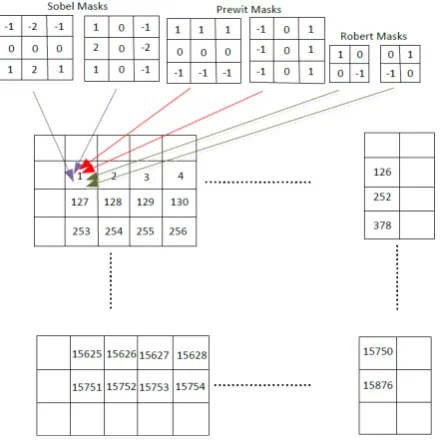
3×3spatial masks and Robert uses two2×2spatial masks to find image edges. These masks are used for computing the gradient of the image intensity values in horizontal and vertical directions. The Sobel, Prewit and Robert masks, which are also called convolution kernels, are shown in Fig. 1 (a)-(c).
By sliding the convolution kernels over the image, the gradient of the image intensity values along x and y directions is computed. Fig. 1 (d) shows intensity values of an image for a typical3×3
sub-window. By applying convolution masks on the sub-window, horizontal (Gx) and vertical edges (Gy) are computed. Formulas
for computingGxandGyusing convolution masks for Sobel,
Pre-wit and Robert operations are shown in 1, 2 and 3 respectively.
Gx= (D6 + 2D7 +D8)−(D0 + 2D1 +D2)
Gy= (D0 + 2D3 +D6)−(D2 + 2D5 +D8)
(1)
Gx= (D0 +D1 +D2)−(D6 +D7 +D8)
Gy= (D2 +D5 +D8)−(D0 +D3 +D6)
(2)
Gx= (D4)−(D8)
Gy= (D5)−(D7)
(3)
The magnitude of gradients for all three operations is obtained by 4.
|G|=qG2
x+G2y (4)
However, it is not convenient to calculate magnitude of gradients in hardware by 4 since it cannot be computed in a single clock cycle as it is desired for pipeline structure. Alternatively, magnitude can be estimated by 5. Since it can get computed in one clock cycle, it is used in our edge detection hardware.
|G|=|Gx|+|Gy| (5)
Although the magnitude implies the strength of the edge at pixel location (x,y), it is not informative for the direction of the edge [15] [18]. The gradient direction is computed by 6.
α(x, y) = tan−1(Gy
Gx
) (6)
The edge detection process for Sobel, Prewit and Robert operations are similar and the only difference is due to using different convo-lution masks.
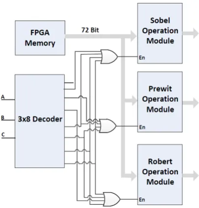
4. FPGA-BASED EDGE DETECTION ARCHITECTURE
The FPGA-based architecture for edge detection is shown in Fig. 2. Three separated hardware modules are defined to perfrom Sobel, Prewit and Robert operations. Each hardware is enabled by a3×8
Fig. 1: Convolution kernels for gradient operations: (a) Sobel (b) Prewit (c) Robert, d) Intensity values of typical3×3sub-window
Table 1. : Relation between inputs and enabling edge detection modules
Inputs
Operation A B C
0 0 0 Nothing
0 0 1 Sobel
0 1 0 Prewit
0 1 1 Robert
1 0 0 Sobel+Prewit
1 0 1 Prewit+Robert
1 1 0 Sobel +Robert
1 1 1 Sobel +Prewit + Robert
are enabled and three different operations are done at the same time in parallel way. As result, the run time of one operation is same as having two or even three different operations.
As it is shown in Fig. 2, each hardware module has 72 bits input from the FPGA memory which stores intensity values of the origi-nal image. This is due to fetching 9 intensity values (i.e.9×8bits) for each edge detection modules at every clock cycle.
4.1 Pipeline Structure
Each edge detection module uses pipeline to speed-up the edge de-tection process of an image located inside FPGA memory. Since the edge detection operation is performed by two convolution ker-nels in parallel, two different pipelines are used for each module. Since there is no dependency between pipeline stages, they are able to perform the edge detection process at each clock cycle without getting stalled. Fig. 3 shows 4 stages of the proposed pipeline struc-ture.
(1) Fetch: 9 intensity values are read for two separated pipelines (GxandGy) of each module. Six intensity values (D0, D1, D2,
D6, D7, D8) are used for computing horizontal gradient (Gx)
and six intensity values (D0, D3, D6, D2, D5, D8) are used for computing vertical gradient (Gy) of the Sobel and Prewit
modules. Four intensity values (D4, D8) and (D5, D7) are used to compute (Gx) and (Gy) of Robert module. So, the number
of pipeline registers in Robert module is less than two other modules. Intensity values are read at one clock cycle and they are passed to the convolution stage by next clock cycle. (2) Convolution:GxandGyare computed for each pixel located
at the center of3×3sub-window (D4). As it was shown in 1 and 2, four additions, two multiplications and one subtrac-tion circuits are needed to computeGxorGy(Soble, Prewit
Fig. 2: FPGA-based edge detection architecture
modules). Based on 3, the Robert module only needs one sub-traction circuit for eitherGxorGy. Having separated
combi-national circuits allows us to perform convolutions in parallel for (Gx) and (Gy). As it is shown in Table 1, if more than one
module is enabled, pipelines of each related modules are run simultaneously.
(3) Absolute Value ofGx ,Gy: ComputedGxandGyvalues of
previous stage, are checked against zero to determine they are positive or negative. If they are negative, they are multiplied by -1 to compute the absolute value in a single clock cycle.
(4) |G|=|Gx|+|Gy|: The gradient magnitude is computed
us-ing 5 by addus-ing the absolute magnitude values ofGxandGy
[image:3.595.103.244.215.361.2]Fig. 3: Pipeline stages for each edge detection module
Fig. 4: One-way parallel method. Since intensity values on borders of an image are not considered for edge detection process, we have not assigned number to them.
4.2 One-way Parallel Edge Detection Architecture
one-way parallel method works based on performing edge detec-tion at one region of an image. One region is the whole intensity values of an image excepting borders. In one-way parallel method, nine intensity values related to each pixel is fetched in row order. So, multiplication by convolution masks is done at the next clock cycle in parallel to computeGxandGy.
[image:4.595.319.554.70.266.2]Fig. 4 depicts the simple picture of the method for the image size of128×128. Firstly, 9 intensity values regarding to pixel 1 are read to form the3×3sub-window. Fetching 9 intensity values continues in row order from pixel 2 to 15876. A separated pipeline is used inside each module for each convolution kernel. Pipeline operations are explained in clock cycle order as below.
Fig. 5: Two-way parallel method, two separated regions are shown by two different colors
(1) Pipeline starts with pixel 1 and it fetches 9 related intensity values to form the3×3sub-window at first clock cycle. (2) While 9 intensity values related to pixel 2 are fetched, 9
in-tensity values regarding to pixel 1 are already passed to con-volution stage. It means that at the same clock cycle, pixel 2 is fetched and convolution for pixel 1 is computed. This con-volution is made for both horizontal and vertical concon-volution masks at the same clock cycle.
(3) 9 intensity values related to pixel 3 are fetched, convolution for pixel 2 is performed and absolute values ofGxandGyare
computed for pixel 1.
(4) 9 intensity values related to pixel 4 are fetched, convolution is performed (pixel 3), absolute values ofGxandGyare
com-puted (pixel 2) and the final magnitude for absolute values|G|
is computed (pixel 1). Pipelines get filled after four clock cy-cles and final magnitude value (G) is calculated for each pixel by one clock cycle.
4.3 Two-way Parallel Edge Detection Architecture
The two- way parallel edge detection architecture extends the one-way process by defining two separated regions in the original im-age. Convolution is perfromed for each region separately by intro-ducing additional convolution kernels and pipelines.
Fig. 5 depicts the operation of the two-way parallel method. Two groups of image intensity values, which split the image along the diagonal, are distinguished by different colors. Two convolution masks and two separated pipelines are used for each edge detec-tion module regarding to each group. For example, fetching of 9 intensity values for pixel 1 and 127 is perfromed simultaneously. Pipelines are run in full speed since there is no data dependency between two pipelines. This effectively doubles the speed in com-parison with one-way method.
[image:4.595.65.286.280.501.2]hard-ware. We later show that going towards m-way of parallelism is effective when the image size increased.
5. SPEED-UP CALCULATION
Any hardware that does not use a pipeline must complete each task to finish an operation. If there arentasks to be executed, and each task needsttime then total runtime is obtained by 7.
Ttotal=nt (7)
[image:5.595.329.531.67.378.2]If each task needsknumber of clocks to be completed, 8 is obtained [5, 13].
Ttotal=nk×clk (8)
whereclkrepresents the clock cycle time. The total runtime of the same task using a pipeline is obtained by 9.
Ttotal−pipeline= (k+n−1)×clk (9)
Speed-up of a hardware benefits pipeline over the equivalent hard-ware is defined by the ratio in 10.
speed−up= nk×clk (k+n−1)×clk =
nk
k+n−1 (10)
As the number of tasks increased, n becomes too larger than k and the speed-up under this condition is simplified by 11.
speed−up=nk
k =k (11)
This means that even when there are many instructions, speed-up gets close to number of the pipeline stages. Therefore, more pipeline stages are desired for greater speed-up.
9 can be easily used to estimate the run time of the edge detection process for one-way parallel method,. For example, we just need to plug in 15870 as number of instructions (n) , 4 as number of each pipeline stageskand 1
Clock F requency asclkfor runtime
estima-tion in Table. 3.
In order to reach to m-way parallelism, 9 should get changed since the longer path determines the total run time of the process. As result, 12 is obtained to calculate the total runtime when there is different instructions regarding to each path.
Ttotal−pipeline= (max(n1, n2, ..., nm)−1 +k)×clk (12)
Wheremis number of different parallel regions that each operates on its own pipeline andkis the number of pipeline stages. These variables are set for runtime estimation of two-way parallelism by plugging 2 intom, 4 intokand Clock F requency1 intoclk. Note, n1=126×2127,n2=125×2126andmax(n1, n2)is 8001.
6. EXPERIMENTAL RESULTS
This section includes three parts. In first part, the implementation results of the one-way and two-way parallel architectures for a given128×128image size is presented. In second part, the run-time of proposed methods for different image sizes are evaluated and the speed-up is estimated. Finally, an extension to higher level of parallelism is proposed when the image size increased in order to guarantee high speed-up.
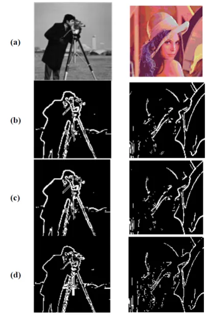
Fig. 6: Edge detection of Lenna & Camera man images, (a) Original images (b) Sobel edge detection (c) Prewit edge detection (d) Robert edge detection
6.1 Implementation
One-way and two-way parallel architectures for a given128×128
image was implemented by Verilog HDL and it was simulated us-ing ModelSim 10.1d from Mentor Graphics Corporation. All im-ages were first read and pre-processed using MATLAB R2010a to resize the image to128×128pixels, convert it to grayscale image, and write the pixel intensity values into a text file in hexadecimal format. The text file is created to use in the hardware simulator; it is loaded into the FPGA memory and read by the edge detection hardware.
Filtered pixels are written into an output text file at each clock cy-cle after the pipeline initialization. Another MATLAB script re-arranges the filtered image pixels into a128×128final image after thresholding. As noted in Table. 1, two or even three filtered output pixels can be generated in a single clock cycle.
Fig. 6 shows the original and final images after performing edge detection by Robert, Sobel and Prewit modules. Robert shows more missed edges and both Sobel and Prewit detect thicker edges as it is expected.
We synthesized both edge detection architectures with Quartus II 9.1 web Edition for the Cyclone IV GX FPGA. Table. 2 shows the hardware resources that were utilized for EP4CGX150DF31C8 FPGA.
ker-Table 2. : Device utilization summery for one & two-way parallel architec-tures
Pins Logic Elements Memory Bits
Available 508 149760 6635520
One-way Used 78 925 1179648 Utilization 15% 1% 18%
[image:6.595.314.549.70.177.2]Two-way Used 143 1588 2359296 Utilization 28% 1% 36%
Table 3. : Runtime results for first & second FPGA-based architectures
Method MATLAB Architecture Lenna Camera man First Second
Sobel 0.12581 0.12256 0.00031 0.00016
Prewit 0.12348 0.12303 0.00031 0.00016
Robert 0.11521 0.11682 0.00031 0.00016
Sobel+Prewit 0.15552 0.14476 0.00031 0.00016
Prewit+Robert 0.15871 0.15128 0.00031 0.00016
Sobel+Robert 0.15435 0.14839 0.00031 0.00016
Sobel +Prewit+Robert 0.16342 0.15330 0.00031 0.00016
nels of two pipelines. Since some combinational circuits are shared between pipelines, total logic elements are not exactly get doubled. Consumed logic elements of second architecture increased by rate of 1.71 but it still consumes 1% due to large number of available logic elements.
Table. 3 presents the runtime of the edge detection process on the FPGA with 50 MHZ clock frequency. The runtime of Soble, Pre-wit and Robert functions are measured in MATLAB R2010a on a machine with 6 Gigabyte RAM and i7 processor. The processor in-cludes 8 cores with a 2.00 GHZ clock frequency. The average of 10 runtimes are accounted for MATLAB and positive edge triggered counters are used to estimate runtime on FPGA.
Table. 3 shows more speed-up for multiple edge detection filters. Although some parallelism is performed using the multiple pro-cessor cores for MATLAB, it cannot fully execute edge detection processes in parallel because of its sequential nature. More edge computation increases runtime in software but FPGA has constant run-time for all combinations due to usage of parallelism between edge detection modules.
Runtime of edge detection process for two-way parallel architec-ture is half of the one-way architecarchitec-ture. This is a direct result of the transition from one-way parallelism to two-way parallelism. Although experimental results show large speed-up, the hardware speed-up depends on the image size. The speed-up calculation for different image sizes and the architecture extension toward m-way parallelism is presented in following sub-sections.
6.2 Speed-up analysis
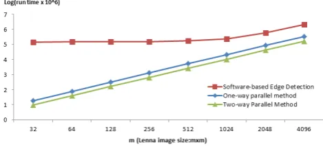
[image:6.595.70.277.98.181.2]Formulas 9 and 12 are used to estimate the runtime of the pro-posed methods on FPGA and MATLAB run edge detection func-tions for different image sizes. Fig. 7 shows the run-time of one-way and two-one-way parallel methods versus the software-based ap-proach when the image size scales by factor of 4. As it is was shown
[image:6.595.63.284.217.346.2]Fig. 7: Run time of software-based edge detection versus one-way and two-way parallel method for different image sizes
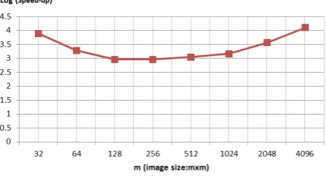
Fig. 8: Speed-up for different image sizes of Lenna Image
in 9, runtime for one-way and two-way methods is linearly related with the image size. If the image size increased by factor of 4, the runtime increased quadratically.
MATLAB R 2010a was used to run each edge detection method for different image sizes. Lenna image was up-sampled by factor of four and the average of worst and best 10 runtimes was measured. Best case is usually achieved when Robert edge detection is only used due to its smaller kernel mask. On the other hand worst case happens when all three edge detections are needed to get run for the given image. The average plot is shown for software-based edge detection in Fig. 7.
When the image size is less than1024×1024, runtime of the edge detection process does not change significantly. It means that the run time of the software-based approach doesnt necessarily follow formula 8 and it doesnt linearly increased due to instruction and data level parallelism on multi-cores [5]. However, when image size is larger than 1024, the run time increased as similar as the proposed parallel methods.
[image:6.595.321.545.235.364.2]Fig. 9: Extending the parallel approach when the image size gets increased
Fig. 10: Final Speed-up using increasing m-way method
6.3 Extension toward m-way parallelism
The extension from 1-way to 2-way and m-ways was shown in for-mula 12 This parallelism extension is beneficial for large image sizes. Transition from one-way to two-way parallel method was previously shown by considering two triangle areas over the image intensity values. The region that covers more intensity values has a longer path and it determines the total runtime. As simple solution, the parallelism can increased when the image size increased. Fig. 9 shows the transition from 2-way to 8-way, when the image size increased from128×128to256×256. The same process can get repetated from 8 way to 32 way when image scales to512×512. Larger image sizes can still be broken into smaller sub-images by utilizing simple two-way parallel blocks. The run time of the full image is still same as the128×128image. It has runtime of two-way parallel method and larger upper triangle still determines the runtime.
Fig. 10 shows the speed-up for increasing m-way. When the image size is between128×128and1024×1024, speed-up is around 1000 and it does not drop for greater image sizes. It actually in-creased for larger images since software approach can no longer efficiently utilize the multiple cores.
7. CONCLUSION
A fast FPGA-based architecture for performing first-order deriva-tive edge detection is presented using a general approach for apply-ing different levels of parallelism. Two architectures are proposed that benefit pipeline structure along with different levels of paral-lelism. Different levels of parallelism are introduced over convo-lution masks, hardware edge detection modules and image
inten-sity values. The parallel hardware architecture achieved significant speed-up over software especially when multiple edge detectors are required. Finally, an extension of the proposed method towards m-level parallelism is presented to guarantees non-decreasing speed-up for large image sizes.
8. REFERENCES
[1] G. Anusha, T. J. Prasad, and D. Narayana. Implementation of sobel edge detection on fpga.Proceeding of the International Journal of Computer Trends and Technology, 3(3):471–475, 2012.
[2] D. G. Bariamis, D. K. Iakovidis, D. E. Maroulis, and S. A. Karkanis. An fpga-based architecture for real time image fea-ture extraction. InProceedings of the 17th International Con-ference on Pattern Recognition, pages 801–814, Cambridge, UK, 2004.
[3] M. P. S. Chikkali and K. Prabhushetty. Fpga based image edge detection and segmentation.Proceeding of the International Journal of Advanced Engineering Sciences and Technologies, 9(2):187–192, 2011.
[4] B. A. Draper, J. R. Beveridge, A. P. W. Bhm, C. Ross, and M. Chawathe. Accelerated image processing on fpgas.IEEE Transactions on Image Processing, 12(12):1543–1551, 2003. [5] J. L. Hannesy and D. A. Patterson.Computer Architecture, A Quantitative Approach. Morgan Kaufmann, 5 edition, 2011. [6] R. Harinarayan, R. Pannerselvam, M. M. Ali, and D. K.
Tri-pathi. Feature extraction of digital aerial images by fpga based implementation of edge detection algorithms. In Proceed-ing of the International Conference on EmergProceed-ing Trends in Electrical and Computer Technology, pages 631–635, Tamil Nadu, India, 2011.
[7] W. Jincheng, Sun Jingrui, and Liu Wenying. Design and im-plementation of video image edge detection system based on fpga. In Proceedings of the 3rd International Congress on Image and Signal Processing, pages 472–476, Yantai, China, 2010.
[8] C. T. Johnston, K. T. Gribbon, and D. G. Bailey. Implement-ing image processImplement-ing algorithms on fpgas. In Proceeding of the Eleventh Electronics New Zealand Conference, pages 118–123, Palmerston North, New Zealand, 2004.
[9] D. Llamocca, C. Carranza, and M. Pattichis. Separable fir fil-tering in fpga and gpu implementations: Energy, performance, and accuracy considerations. InProceedings of the Interna-tional Conference on Field Programmable Logic and Appli-cations, pages 363–368, Chania, 2011.
[10] R. Maini and J. S. Sohal. Performance evaluation of prewit edge detector for noisy images. Proceeding of the Interna-tional Journal on Graphics, Vision and Image Processing, 6(3):90–95, 2006. December.
[11] S. K. C. J. Majumdar. A novel architecture for real time imple-mentation of edge detectors on fpga.Proceeding of the Inter-national Journal of Computer Science Issues, 8(1):193–202, 2011.
[12] R. Mehra and S. Verma. Area efficient fpga implementation of sobel edge detector for image processing application. Pro-ceeding of the International Journal of Computer Applica-tions, 56(16), 2012.
[14] J. M. Ramirez, E. M. Flores, j. Martinez-Carballido, R. En-riquez, V. Alarcon-Aquino, and D. Baez-Lopez. An fpga-based architecture for linear and morphological image filter-ing. InProceeding of the 20th International Conference on Electronics, Communications and Computer, pages 90–95, Cholula, Mexico, 2010.
[15] V. Sanduja and R. Patial. Sobel edge detection using parallel architecture based on fpga.Proceeding of the International Journal of Applied Information Systems, 3(14), 2012. [16] H. Santanu, D. Bhattacharjee, M. Nasipuri, and D. K. Basu. A
fast fpga based architecture for sobel edge detection. In Pro-ceeding of the 16th International Conference on Progress in VLSI Design and Test, pages 300–306, Shibpur, India, 2012. Springer Berlin Heidelberg.
[17] R. Szeliski.Computer Vision: Algorithms and Applications. Morgan Kaufmann, 2010.