48 | P a g e
DESIGN AND ANALYSIS OF FLYWHEEL FOR A PUNCHING
MACHINE OPERATION
*Sk Suhal
1, B. Siddeswara Rao
2, Ramabathina Srinivasulu
31M.tech Student, Department of Mechanical Engineering, Brahmaiah College of Engineering, North Rajupalem, Nellore, Andhra Pradesh, India 524366.
2Principal, Department of Mechanical Engineering, Brahmaiah College of Engineering, North Rajupalem, Nellore, Andhra Pradesh, India 524366.
3Assistant professor, Department of Mechanical Engineering, Brahmaiah College of Engineering, North Rajupalem, Nellore, Andhra Pradesh, India 524366.
Abstract: A flywheel is an inertial energy-storage device. It absorbs mechanical energy and serves as a reservoir, storing energy during the period when the supply of energy is more than the requirement and releases it during the period when the requirement of energy is more than the supply. The performance of a flywheel can be attributed to three factors, i.e., geometry of flywheel, rotational speed and material strength.
In the present work, a flywheel design problem is formulated for punching machine which has to be make holes of 30 holes/minute on a steel plate of 18mmthickness with space limitation that is the diameter of flywheel should not exceed 1000mm, hence it can be observed that the design of the flywheel is to be carried out (based) on the availability of space limitation and accordingly the fluctuation of energy, and dimensions of the flywheel were determined. The stresses induced in the flywheel were considered for safe design.
Key words: fly wheel, punching machine, disk and arm.
I. INTRODUCTION:
A flywheel is an inertial energy-storage device. It absorbs mechanical energy and serves as a reservoir, storing energy during the period when the supply of energy is more than the requirement and releases it during the period when the requirement of energy is more than the supply A flywheel used in machines serves as a reservoir which stores energy during the period when the supply of energy is more than the requirement and releases it during the period when the requirement of energy is more than supply.
In case of steam engines, internal combustion engines, reciprocating compressors and pumps, the energy is developed during one stroke and the engine is to run for the whole cycle on the energy produced during this one stroke. In I.C. engines, the energy is developed only during power stroke which is much more than the engine load, and no energy is being developed during suction, compression and exhaust strokes in case of four stroke engines and during compression in case of two stroke engines. The excess energy developed during power stroke is absorbed by the flywheel and releases it to the crankshaft during other strokes in which no energy is developed, thus rotating the crankshaft at a uniform speed. the flywheel absorbs energy, its speed increases and when it releases, the speed decreases. Hence a flywheel does not maintain a constant speed, it simply reduces the fluctuation of speed.
In machines where the operation is intermittent like
punching machines, shearing machines, riveting
machines, crushers etc., the flywheel stores energy from the power source during the greater portion of the operating cycle and gives it up during a small period of the cycle. Thus the energy from the power source to the machines is supplied practically at a constant rate throughout the operation.
The flywheel does not maintain a constant speed, it simply reduces the fluctuation of speed. In other words, a flywheel controls the speed variations caused by the fluctuation of the engine turning moment during each cycle of operation. It does not control the speed variations caused by the varying load. The stored kinetic energy is to absorb the variations in torque during a machine cycle, a flywheel smooths the fluctuating speed of a machine and reduces undesirable transient loads. A flywheel limits the speed variation over one cycle and has minimal effect on the average speed.
49 | P a g e
II. LITERATURE SURVEY:
S. M. Dhengle, Dr. D. V. Bhope, S. D. Khamankar evaluated the stresses in the rim and arm using finite element method and results are validated by analytical calculations .The models of flywheel having four, six and eight no. arms are developed for FE analysis. The FE analysis is carried out for different cases of loading applied on the flywheel and the maximum Von mises stresses and deflection in the rim are determined. From this analysis it is found that Maximum stresses induced are in the rim and arm junction. Due to tangential forces, maximum bending stresses occurs near the hub end of the arm. It is also observed that for low angular velocity the effect gravity on stresses and deflection of rim and arm is predominant.
M. lavakumar, R. Prasannasrinivas (2013) presented a paper on the design and analysis of flywheel to minimize the fluctuation in torque, the flywheel is subjected to a constant rpm. The objective of present work is to design and optimize the flywheel for the best material. The flywheel is modeled with solid 95 (3-D element), the modeled analyses using free mesh. The FEM mesh is refined subject to convergence criteria. Preconditioned conjugate gradient method is adopted during the solution and for deflections. Von-misses stress for both materials (mild steel and mild steel alloy) are compared, the best material is suggested for manufacture of flywheel.
Rathod Balasaheb S, Satish. M. Rajmane have deigned flywheel which is used for punching press operation for punching machine which has to be make holes of 30 holes/minute in a steel plate of 18mm thickness with space limitation that is the diameter of flywheel should not exceed 1000mm, hence it can be observed that the design of the flywheel is to be carried out (based) on the availability of space limitation.
In 2016, a paper with an aim to design composite flywheel material for high-speed energy storage, was published by Michael A. Conteh & Emmanuel C. Nsofor. In this paper, lamina and laminate mechanical properties of materials suitable for flywheel high-speed energy storage were evaluated using analytical studies. Along with analytical studies results were also evaluated on CADEC-online software. By the observations it was concluded that, in order to obtain higher flywheel energy density, material having higher strength and lower density is required.
Sushama G Bawaneet. al., (2012) [6] By using optimization technique various parameter like material, cost for flywheel can be optimized and by applying an approach for modification of various working parameter like efficiency, output, energy storing capacity, we can compare the result with existing flywheel result. Based on the dynamic functions, specifications of the system the main features of the flywheel are initially determined; the detail design study of flywheel is done. Then FEA
analysis for more and more designs in diverse areas of engineering is being analyzed through the software. FEA provides the ability to analyze the stresses and displacements of a part or assembly, as well as the reaction forces other elements are to impose. This paper guides the path through flywheel design, and analysis the material selection process. The FEA model is described to achieve a better understanding of the mesh type, mesh size and boundary conditions applied to complete an effective FEA model. At last the design objective could be simply to minimize cost of flywheel by reducing material.
Sudipta Sahaet. al., (2013) [4] the performance of a flywheel can be attributed to three factors, i.e., material strength, geometry (cross-section) and rotational speed. While material strength directly determines kinetic energy level that could be produced safely combined (coupled) with rotor speed, this study solely focuses on exploring the effects of flywheel geometry on its energy storage/deliver capability per unit mass, further defined as Specific Energy. Proposed Computer aided analysis and optimization procedure results show that smart design of flywheel geometry could both have a significant effect on the Specific Energy performance and reduce the operational loads exerted on the Shaft/bearings due to reduced mass at high rotational speeds. This paper specifically studies the most common five different geometries (i.e., straight/concave or convex shaped2D)
III. PROPOSED WORK:
The present work is focused on the Design of a flywheel which is used for punching press operation. The punching machine which has to be make holes of 25mm dia with a speed of 30 holes/minute in a steel plate of 18mm thickness with space limitation that is the diameter of flywheel should not exceed 1000mm. for the above consideration a flywheel is designed with conventional design procedure. With The calculated dimensions of the Flywheel the Geometrical model has been done in the engineering Analysis package ANSYS16.0 with the concept of Axi-symmetric approach. The geometric modeled is meshed with 4Node Quadratic Solid Element and conducted stress analysis at rated RPM using the ANASYS 16.0. The results of the ANSYS and Conventional Analysis were compared.
Common uses of a flywheel include:
Smoothing the power output of an energy source. For example, flywheels are used in reciprocating engines because the active torque from the individual pistons is intermittent.
50 | P a g e
Flywheels are typically made of steel and rotate on conventional bearings; these are generally limited to a maximum revolution rate of a few thousand RPM. High energy density flywheels can be made of carbon fiber composites and employ magnetic bearings, enabling them to revolve at speeds up to 60,000 RPM.
A. Design procedure of flywheel:
The design of flywheel involves with various formulae and procedure. The design procedure involves various technical terms and assumptions. In this chapter discuss the basic terminology and its definitions and technical data that requires the flywheel design for various applications.
Design Approach: There are two stages to the design of a flywheel. First, the amount of energy required for the desired degree of smoothening must be found and the (mass) moment of inertia needed to absorb that energy determined. Then flywheel geometry must be defined that caters the required moment of inertia in a reasonably sized package and is safe against failure at the designed speeds of operation.
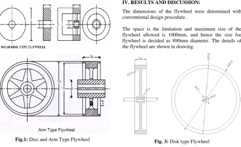
Geometry of Flywheel: The geometry of a flywheel may be as simple as a cylindrical disc of solid material, or may be of spoked construction like conventional wheels with a hub and rim connected by spokes or arms Small fly wheels are solid discs of hollow circular cross section. As the energy requirements and size of the flywheel increases the geometry changes to disc of central hub and peripheral rim connected by webs and to hollow wheels with multiple arms.
Fig.1: Disc and Arm Type Flywheel
The latter arrangement is a more efficient of material especially for large flywheels, as it concentrates the bulk of its mass in the rim which is at the largest radius. Mass at largest radius contributes much more since the mass moment of inertia is proportional to mr2
Fig. 2: Radius Vs Stress
The point of most interest is the inside radius where the stress is a maximum. What causes failure in a flywheel is typically the tangential stress at that point from where fracture originated and upon fracture fragments can explode resulting extremely dangerous consequences, Since the forces causing the stresses are a function of the rotational speed also, instead of checking for stresses, the maximum speed at which the stresses reach the critical value can be determined and safe operating speed can be calculated or specified based on a safety factor.
IV. RESULTS AND DISCUSSION:
The dimensions of the flywheel were determined with conventional design procedure.
The space is the limitation and maximum size of the flywheel allowed is 1000mm, and hence the size foe flywheel is decided as 890mm diameter. The details of the flywheel are shown in drawing.
51 | P a g e
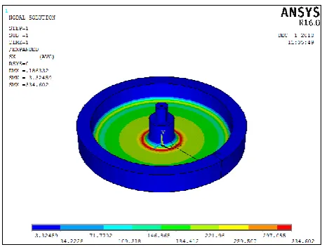
For safe working conditions of the flywheel with a self weight of 253.5 Kgf and rotating at 250RPM is the maximum stress induced in the Rim portion is determined
as 1.92MN/M2. These stress were induced in the flywheel
along the Radial Direction. For the same working conditions, the ANSYS results shows maximum induced stress in the rim as 3.2 MN/m2 .The maximum allowable stresses in the fly wheel is considered as 300MN/m2.
Hence the design is considered as safe.
Fig. 4: Radial Stress in the Flywheel
It is also observed that the maximum stress is developed at hub, but it considered as stress concentration at joining of web and hub partition of the flywheel. This can be reduced by modifying the suitable fillet radius. Similar results were observed from the Von mises stress as shown in the diagram.
Fig. 5: Von-mi stresses
Fig. 6: Radial Stresses at Points
The radial stresses captured at selected points on the flywheel to confirm the safe design of the flywheel.
Fig.7: Displacement in the Radial Direction
From the plot it is concluded that there is no much deformation. Hence there are no risks for cracks, failures location on the flywheel for given working conditions.
V. CONCLUSION:
The flywheel for punching machine has been designed for required space limitation and working conditions. As the current problem is related to the design of flywheel with consideration(limitation) of the space availability that is maximum space should be less than 1m, but after carrying out design the outer diameter of flywheel obtained as 0.89m which is less than the required condition, hence can be concluded as design is safe.
The induced stress was determined in the rim of the flywheel with conventional calculations.
52 | P a g e
observed stresses are found to be less than the allowable stresses. Therefore this design of the flywheel for the punch press is found to be safe.
BIBLOGRAPHY:
1. M. Lavakumar, R. Prasannasrinivas, Design and
analysis of light weight motor vehicle flywheel, International Journal of Computer Trends and Technology (IJCTT) – volume 4 Issue -7 July 2013. 2. S. M. Dhengle, Dr. D. V. Bhope, S. D. Khamankar,
Investigation of stresses in arm type rotating flywheel, International Journal of Engineering Science and Technology (IJEST), Vol. 4 No.02 February 2012.
3. Rathod Balasaheb S, Satish. M. Rajmane, A Case
Study on Design of a Flywheel for Punching Press Operation International Journal of Engineering and Advanced Technology (IJEAT) ISSN: 2249 – 8958, Volume-3, Issue-4, April 2014.
4. Akshay P. Punde, G. K. Gattani, "Analysis of
flywheel", "International Journal of Modern Engineering Research (IJMER)", Vol.3, Issue.2, March-April. 2013, pp-1097-1099, ISSN: 2249-6645. 5. Pagoti Lokesh, Mr. B. Ashok Kumar, "Design and Analysis of Fly Wheel and By Using CATIA and ANSYS Software", "International Journal & Magazine of Engineering Technology, Management and Research", A Peer Reviewed Open Access International Journal, ISSN No: 2348-4845.
6. Michael A. Conteh, Emmanuel C. Nsofor,
“Composite flywheel material design for high-speed energy storage”, Journal of Applied Research and Technology 14 (2016) 184-190.
7. Sushama G Bawane , A P Ninawe and S K
Choudhary, Analysis and optimization of flywheel, International Journal of Mechanical engineering and robotics Vol. 1, No. 2, July 2012.
8. Sudipta Saha, Abhi Bose, G. Sai Tejesh, S.P.
Srikanth, computer aided design & analysis on flywheel for greater efficiency, International Journal of Advanced Engineering Research and Studies, IJAERS/Vol. I/ Issue II/January-March, 2012/299-301.
9. Text book of Theory of machines by R.S Khurmi, S.
Chandh Publications-2012.
10. Text book of Design of Machine Elements by
VB.BANDARI, Tata McGraw– Hill publishing company limited-2006.
11. Text book of Design of Machine Elements by R.S