13
*Corresponding authoremail address: [email protected]
Influence of heat generation on the phase transformations and impact
responses of composite plates with embedded SMA wires
A. Niknamiand M. Shariyat*
Faculty of Mechanical Engineering, K.N. Toosi University of Technology, Tehran, Iran
Article info: Abstract
In the present research, in contrast to the available papers, not only the superelasticity but also the shape memory effects are taken into account in determination of the impact responses. At the same time, in addition to modifying Brinson’s model for the shape memory alloys (SMAs), to include new parameters and loading events, and Hertz contact law, distributions of the SMA phases are considered to be both localized and time-dependent. Furthermore, effects of the impact-induced heat generation and mechanical energy on the resulting histories of the martensite phase volume fraction, stress-strain, temperature, lateral deflection, and contact force are investigated. The generated heat in the SMA wires during the impact is determined through using a Helmholtz free energy function including the latent heat of the phase transformation. The resulting governing equations are solved by the finite element method. The nonlinear refined constitutive laws are solved through a return-mapping Newton-Raphson procedure. Results reveal that incorporation of the heat generation effects is significant in medium/high-velocity impacts or when the stress field is almost uniform. Received: 10/11/2015
Accepted: 08/03/2016 Online: 03/03/2017
Keywords:
Shape memory alloy, Impact,
Phase transformation, Heat generation, Hybrid composite plate.
1. Introduction
In many cases, the structural damping does not render adequately dissipation of the energies of the undesired structural oscillations. Attenuation of the vibration amplitude may be accomplished through using the SMA elements that consume the undesired energy for the phase transformations of the microstructure of the material. Some limited authors have studied low velocity impact responses of composite plate with embedded SMA wires. Khalili et al. [1], Shokuhfar et al. [2], Meo et al. [3], and Kim et al. [4] are among the well-known researchers
14
and Shariyat and Farzan Nasab [7, 8] proposed modified contact laws that overcome these shortcomings. Using outcomes of these researches and modifying Brinson’s model, Shariyat and Moradi [9] investigated impact responses of hybrid composite plates with embedded SMA wires. Recently, Shariyat and Hosseini [10] have extended these novelties through accurate eccentric impact analysis of the preloaded SMA composite plates, proposing a new mixed-order hyperbolic global-local plate theory.
Effects of the loading rate on responses of the abruptly loaded SMA structures were discussed by some authors. In order to simulate the strain rate effect in phase transformation of the SMA, Helm and Haupt [11] proposed a model within the continuum thermo-mechanics framework and showed that the SMAs exhibit strong thermo-mechanical coupling and consequently, the material model must comply with the second law of thermodynamic. Tobushi et al. [12] studied the influence of the load-rate on superelastic properties of the TiNi shape memory alloy and demonstrated that the temperature increases in proportion to the strain rate. Kadkhodaei et al. [13] presented a Helmholtz free energy expression for the SMAs that involved effects of the strain rate. Other studies in this field have been published by Monteiro et al. [14], Morin et al. [15], and Roh [16].
All the aforementioned impact researches have only considered effects of the superelastic characteristics of the SMA wires on the impact responses. In the present analysis, effects of the superelasticity and shape memory natures of the SMA wires of the impacted SMA composite plates are considered simultaneously, for the first time. In addition to refining Brinson’s model for the SMAs and Hertz contact law, influences of the impact-induced-heat on the resulting phase transformations and responses are considered based on the energy balance and thermodynamic equations. The finite element form of the governing equations is solved by an iterative numerical time integration method wherein the nonlinear constitutive equations are solved by a Newton-Raphson procedure, within each time step.
2. The governing equations
2.1. The thermodynamic formulation
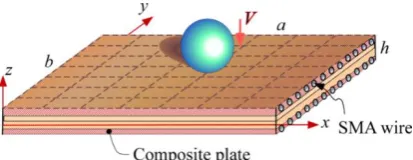
Length, width, and thickness of the plate are denoted by a, b, and h, respectively and initial velocity and radius of the rigid spherical indenter are denoted by V and R, respectively (Fig. 1).
Fig. 1. The configuration of the composite plate with embedded SMA wires, and the employed rectangular elements.
Effects of transformation rate of the SMA wires on the resulting temperature rise may be determined based on the first law of thermodynamics [17, 18]:
𝑞
𝑖,𝑖− 𝜎
𝑖𝑗𝜀̇
𝑖𝑗+ 𝜌
0(𝑓̇ + 𝑇̇𝑆)
− 𝜌
0(𝑟 − 𝑇𝑆̇) = 0
(1)
where 𝑞, 𝜎𝑖𝑗, 𝜀̇𝑖𝑗, 𝜌0, 𝑓, 𝑇, 𝑆, and 𝑟 are the heat
flux vector, Cauchy’s stress tensor, strain-rate tensor, mass density, Helmholtz free energy, temperature, entropy, and the internal heat generation, respectively. The comma symbol denotes a partial differentiation with respect to the indicated parameter. On the other hand, based on the second law of thermodynamics:
𝜎
𝑖𝑗= 𝜌
0𝜕𝑓
𝜕𝜀
𝑖𝑗𝑆 = −
𝜕𝑓
𝜕𝑇
Λ
= −𝜌
0𝜕𝑓
𝜕𝜉
(2)
15
of SMAs may be proposed by extending that of Ref. [13]:
𝑓 =
𝐶
𝑖𝑗𝑘𝑙𝜀
𝑖𝑗𝜀
𝑘𝑙2𝜌
0−
𝛽
𝑖𝑗(𝑇 − 𝑇
0)𝜀
𝑖𝑗𝜌
0−
𝜀
𝑙𝜉
𝑠𝐸
𝑠𝑉
𝑠𝜀
11𝜌
0+ 𝑉
𝑠𝜆
𝑇
∗(𝑇 − 𝑇
∗)𝜉
+ 𝐶
𝐸(𝑇 − 𝑇
0− 𝑇𝑙𝑛 (
𝑇
𝑇
0))
(3)
where 𝐶𝑖𝑗𝑘𝑙, 𝛽𝑖𝑗, 𝜀𝑙, 𝜉𝑠, 𝐸𝑠, 𝑉𝑠, 𝜆, 𝑇∗, 𝐶𝐸, and 𝑇0
are the elasticity tensor, stress-temperature coupling coefficients, maximum recoverable strain, stress-induced martensite volume fraction, modulus of the SMA, SMA volume fraction of the hybrid composite, latent heat of the phase transformation, critical temperature, the specific heat of the material, and initial temperature, respectively. Comparing Eqs. (2) and (3), the transformation driving force and entropy may be written in the following explicit forms:
Λ
= −𝜌
0𝜕𝑓
𝜕𝜉
= 𝜀
𝑙𝐸
𝑠𝑘
𝑠𝜀
11− 𝜌
0𝑉
𝑠𝜆
𝑇
∗(𝑇 − 𝑇
∗)
(4)
𝑆 = −
𝜕𝑓
𝜕𝑇
=
𝛽
𝑖𝑗𝜀
𝑖𝑗𝜌
0− 𝑉
𝑠𝜆
𝑇
∗𝜉
+ 𝐶
𝐸𝑙𝑛 (
𝑇
𝑇
0)
(5)
The second term of the last side of Eq. (5), i.e.,
Vs λ
T∗ξ that has been ignored by other
researchers is retained in the present research. The rate form of the entropy equation (5) may be written as follows:
𝑆̇ =
𝛽
𝑖𝑗𝜀̇
𝑖𝑗𝜌
0− 𝑉
𝑠𝜆
𝑇
∗𝜉̇ + 𝐶
𝐸𝑇̇
𝑇
(6)
Generally, in low-velocity impacts, the first term of right-hand side of Eq. (6), i.e., 𝛽𝑖𝑗𝜀̇𝑖𝑗
𝜌0 may
be neglected in comparison to the second one,
that contains the heat generated by the latent heat [17, 18].
𝑞
𝑖,𝑖− (𝜀
𝑙𝐸
𝑠𝜀
11+ 𝜌
0𝜆)𝑉
𝑠ξ
̇
+ 𝜌
0𝐶
𝐸𝑇̇ = 0
(7)
Equation (7) reveals that the martensite transformation produces heat and causes temperature rise and vice versa.
2.2. The refined constitutive and contact laws
The constitutive relation of the ith layer of the plate in the principal coordinates of the material is:
{
𝜎
1𝜎
2𝜏
12𝜏
13𝜏
23}
=
[
𝑄
11𝑄
120
0
0
𝑄
12𝑄
220
0
0
0
0
𝑄
440
0
0
0
0
𝑄
550
0
0
0
0
𝑄
66]
{
𝜀
1−
α
1∆T
𝜀
2−
α
2∆T
𝛾
12𝛾
13𝛾
23}
= 𝑸(𝜺 − 𝜺
𝑻)
(8
)
where the subscripts 1, 2, and 3 correspond to the fiber direction, the in-plane transverse direction of the fiber and the out-of plane transverse direction of the fiber, respectively, and the non-zero components of the reduced stiffness matrix 𝑄 are:
𝑄
11=
𝐸
11 − 𝜈
12𝜈
21𝑄
22=
𝐸
21 − 𝜈
12𝜈
21𝑄
12=
𝜈
12𝐸
21 − 𝜈
12𝜐
21, 𝑄
44= 𝐺
12𝑄
55= 𝐺
13, 𝑄
66= 𝐺
2316
where E, ν, G, α, and 𝜺𝑻 are Young’s modulus,
Poisson’s ratio, shear modulus, the coefficient of the thermal expansion, and vector of the thermal strains, respectively. Based on Brinson’s constitutive equation of the shape memory alloy [19], the stress and strain quantities may be related through the martensite volume fraction (ξ) as:
σ
−
σ
0= 𝐸(𝜉)𝜀 − 𝐸(𝜉
0)𝜀
0+
Ω
(𝜉)𝜉
𝑠−
Ω
(𝜉
0)𝜉
𝑠0+
Θ
(𝑇 − 𝑇
0),
𝜉 = 𝜉
𝑠+ 𝜉
𝑇(10)
where Ω is the transformation function and ξs
and ξT represent the stress- and
temperature-induced martensite volume fractions, respectively. The subscript 0 denotes the initial quantities of the local or global event under investigation. The Young’s modulus of elasticity of the SMA is dependent on the martensite and austenite moduli; so that, according to the rule of mixtures:
𝐸(𝜉) = 𝐸
𝐴+ 𝜉(𝐸
𝑀− 𝐸
𝐴)
Ω
(𝜉) = −𝜀
𝑙𝐸(𝜉)
(11)
where 𝐸𝐴 and 𝐸𝑀 are Young’s moduli of the
austenite and martensite phases, respectively. In this regard, the following kinetic laws of the transformation may be used:
(i) Conversion from the austenite to the de-twinned martensite phase (𝜎𝑠𝑐𝑟+ 𝐶𝑀(𝑇 −
𝑀𝑠) < 𝜎 < 𝜎𝑓𝑐𝑟+ 𝐶𝑀(𝑇 − 𝑀𝑠) and 𝑇 >
𝑀𝑠):
𝜉
𝑠=
1 − 𝜉
𝑠02
× cos {
𝜋
𝜎
𝑠𝑐𝑟− 𝜎
𝑓𝑐𝑟
[𝜎
− 𝜎
𝑓𝑐𝑟− 𝐶
𝑀
(𝑇 − 𝑀
𝑠)]} +
1 + 𝜉
𝑠02
𝜉
𝑇= 𝜉
𝑇0−
𝜉
𝑇01 − 𝜉
𝑠0(𝜉
𝑠− 𝜉
𝑠0)
(12)
(ii) Conversion from de-twinned martensite to austenite phase. For 𝑇 > 𝐴𝑠 and 𝐶𝐴(𝑇 −
𝐴𝑓) < 𝜎 < 𝐶𝐴(𝑇 − 𝐴𝑠)
𝜉 =
𝜉
02
× {cos [
𝜋
𝐴
𝑓− 𝐴
𝑠(𝑇 − 𝐴
𝑠−
𝜎
𝐶
𝐴)] + 1}
𝜉
𝑠= 𝜉
𝑠0−
𝜉𝑠0
𝜉0
(𝜉
0− 𝜉)
,
𝜉
𝑇= 𝜉
𝑇0−
𝜉
𝑇0𝜉
0(𝜉
0− 𝜉)
(13)
𝐴𝑠, 𝐴𝑓, and 𝑀𝑠 correspond to the start and finish
temperatures of the austenite phase transformation and temperature of the start of the martensite transformation, respectively.
𝐶𝑀, 𝐶𝐴, 𝜎𝑠𝑐𝑟 and 𝜎𝑓𝑐𝑟 are the SMA
transformation properties [20]. Since the structure is subjected to thermo-mechanical loads, Eq. (8) may be modified for a layer with embedded SMA wires in the transformed coordinates, as:
𝝈
̅ =
{
𝜎
xx𝜎
yy𝜏
xy𝜏
xz𝜏
yz}
=
[
𝑄
11𝑄
12𝑄
160
0
𝑄
12𝑄
22𝑄
260
0
𝑄
16𝑄
26𝑄
660
0
0
0
0
𝑄
45𝑄
550
0
0
𝑄
44𝑄
45]
×
{
{
𝜀
𝑥𝑥𝜀
𝑦𝑦𝛾
𝑥𝑦𝛾
𝑥𝑧𝛾
𝑦𝑧}
−
{
α
𝑥𝑥Δ
𝑇
α
𝑦𝑦Δ
𝑇
2
α
xy0
0
}
}
−
{
𝑘
𝑠𝐸
𝑠𝜉
𝑠𝜀
𝐿cos
2(𝜃)
𝑘
𝑠𝐸
𝑠𝜉
𝑠𝜀
𝐿sin
2(𝜃)
𝑘
𝑠𝐸
𝑠𝜉
𝑠𝜀
𝐿sin(𝜃) cos(𝜃)
0
0
}
= 𝑸
̅(𝜺̅ − 𝜺̅
𝑇) − 𝝈
̅
s17
where, Es and ε̅T are the modulus of elasticity
of the SMA material and thermal strains vector in the body coordinates of the material, respectively. The non-zero components of the transformed reduced stiffness matrix 𝑸̅ are [21]:
𝑄
11= 𝑄
11𝑐𝑜𝑠
4𝜃
+ 2(𝑄
12+ 2𝑄
66)𝑠𝑖𝑛
2𝜃𝑐𝑜𝑠
2𝜃
+ 𝑄
22𝑠𝑖𝑛
4𝜃
𝑄
12= (𝑄
11+ 𝑄
22− 4𝑄
66)𝑠𝑖𝑛
2𝜃𝑐𝑜𝑠
2𝜃
+ 𝑄
12(𝑠𝑖𝑛
4𝜃
+ 𝑐𝑜𝑠
4𝜃)
𝑄
22= 𝑄
11𝑠𝑖𝑛
4𝜃
+ 2(𝑄
12+ 2𝑄
66)𝑠𝑖𝑛
2𝜃𝑐𝑜𝑠
2𝜃
+ 𝑄
22𝑐𝑜𝑠
4𝜃
𝑄
16= (𝑄
11− 𝑄
12− 2𝑄
66)𝑠𝑖𝑛𝜃𝑐𝑜𝑠
3𝜃
+ (𝑄
12− 𝑄
22+ 2𝑄
66)𝑠𝑖𝑛
3𝜃𝑐𝑜𝑠𝜃
𝑄
26= (𝑄
11− 𝑄
12− 2𝑄
66)𝑠𝑖𝑛
3𝜃𝑐𝑜𝑠𝜃
+ (𝑄
12− 𝑄
22+ 2𝑄
66)𝑠𝑖𝑛𝜃𝑐𝑜𝑠
3𝜃
𝑄
66= (𝑄
11+ 𝑄
22− 2𝑄
12− 2𝑄
66)𝑠𝑖𝑛
2𝜃𝑐𝑜𝑠
2𝜃
+ 𝑄
66(𝑠𝑖𝑛
4𝜃
+ 𝑐𝑜𝑠
4𝜃)
𝑄
44= 𝑄
44𝑐𝑜𝑠
2𝜃 + 𝑄
55
𝑠𝑖𝑛
2𝜃
𝑄
45= (𝑄
55− 𝑄
44)𝑐𝑜𝑠𝜃𝑠𝑖𝑛𝜃
𝑄
55= 𝑄
55𝑐𝑜𝑠
2𝜃 + 𝑄
44𝑠𝑖𝑛
2𝜃
𝛼𝑥𝑥
= 𝛼
1𝑐𝑜𝑠
2𝜃 + 𝛼
2
𝑠𝑖𝑛
2𝜃
𝛼𝑦𝑦
= 𝛼
1𝑠𝑖𝑛
2𝜃 + 𝛼
2
𝑐𝑜𝑠
2𝜃
𝛼𝑥𝑦
= (𝛼
1− 𝛼
2)𝑠𝑖𝑛𝜃𝑐𝑜𝑠𝜃
(15)
Since it is assumed that the SMA wires are parallel to the composite fibers, the following relations may be used to determine the effective material properties of each layer in the principal directions of the fibers, using the
micromechanical relations appeared in Eq. (11) [22]:
𝐸
1= 𝐸
1𝑐𝑉
𝑐+ 𝐸
𝑠𝑉
𝑠𝐸
2= 𝐸
2𝑐𝐸
𝑠⁄
(𝑉
𝑐𝐸
𝑠+ 𝑉
𝑠𝐸
2𝑐)
𝐺
12= 𝐺
12𝑐𝐺
𝑠⁄
(𝑉
𝑐𝐺
𝑠+ 𝑉
𝑠𝐺
12𝑐)
𝐺
13= 𝐺
13𝑐𝐺
𝑠⁄
(𝑉
𝑐𝐺
𝑠+ 𝑉
𝑠𝐺
13𝑐)
𝜈
12= 𝜈
12𝑐𝑉
𝑐+ 𝜈
𝑠𝑉
𝑠𝜌 = 𝜌
𝑐𝑉
𝑐+ 𝜌
𝑠𝑉
𝑠𝛼
1= 𝛼
1𝑐𝑉
𝑐+ 𝛼
𝑠𝑉
𝑠𝛼
2= 𝛼
2𝑐𝛼
𝑠/(𝛼
2𝑐𝑉
𝑠+ 𝛼
𝑠𝑉
𝑐)
(16)
where the subscripts s and c stand for the SMA and composite materials, respectively. The traditional Hertz contact law should be modified based on a proper micromechanical model and a further refinement that considers the finite thickness of the plate is required. For a transversely isotropic plate impacted by a rigid spherical indenter, Turner’s modification of Hertz law [23] may be further enhanced based on the employed micromechanical model, as follows [24]:
𝐹𝑐=
8
3𝐺12√2𝑅𝛼̂ 3 2⁄
(1 − 𝜈12)√ 𝐸1⁄𝐸2−𝜈132
1−𝜈122 √√ 𝐸1⁄𝐸2−𝜈132
1−𝜈122 +
(𝐸1⁄2𝐺13)−𝜈13(1+𝜈12) 1−𝜈122
(17)
where, α̂ is the indentation value. For the unloading phase, Yang and Sun law [25] may be employed:
𝐹
𝑐= 𝐹
𝑚𝑎𝑥(
𝛼̂ − 𝛼̂
0𝛼̂
𝑚𝑎𝑥− 𝛼̂
0)
5 2
(18)
where, 𝐹𝑚𝑎𝑥 is the maximum contact force
reached during the impact, αmax is the
maximum indentation corresponds to Fmax and
α0 is the permanent indentation, if any.
2.3. The governing nonlinear equations of motion
18
𝜹(𝑥, 𝑦, 𝑧, 𝑡) = { u v w } = [
𝓝 𝟎 −4𝑧
2
3ℎ2 𝓝,𝑥 (𝑧 −
4𝑧2
3ℎ2) 𝓝 𝟎
𝟎 𝓝 −4𝑧
2
3ℎ2 𝓝,𝑦 𝟎 (𝑧 −
4𝑧2 3ℎ2) 𝓝
𝟎 𝟎 𝓝 𝟎 𝟎 ]
× { 𝐔 𝐕 𝐖 𝚽𝐱 𝚽𝐲}
= ℕ(𝑥, 𝑦, 𝑧)𝚫(𝑡)
(19)
where 𝛅 and 𝚫 are the displacement components and nodal displacement components vectors, respectively. U, V, and W are the nodal displacements of the reference plane, and 𝚽𝐱
and 𝚽𝐲 are nodal rotations of the cross-section
in the x–z and y–z planes, respectively. 𝓝 is the shape functions matrix of the quadrilateral element [26]. Therefore:
𝜺̅ = { 𝜀x 𝜀y 𝛾xy 𝛾xz
𝛾yz}
=
[ 𝜕
𝜕𝑥 0 0
0 𝜕 𝜕𝑦 0 𝜕
𝜕𝑦 𝜕 𝜕𝑥 0 𝜕 𝜕𝑧 0 𝜕 𝜕𝑥 0 𝜕 𝜕𝑧 𝜕 𝜕𝑦] 𝜹
= 𝓓ℕ𝚫 = 𝓑𝚫
(20)
The transverse distribution of the temperature rise may be assumed to linear; an assumption that may be justified, especially for the thin plates (as using the first-order plate theory):
𝜃
∗(x, y, z, t) = T
0(x, y, t)
+ zT
1(x, y, t)
= [𝓝 𝑧𝓝] {
𝑻
𝑻
𝟎𝟏
}
= 𝓖𝚯
(21)
The governing equations may be derived using the variational principles. Based an approach proposed earlier by Serra and Bonaldi [27] (not for SMAs) the residues of the energy balance Eq. (7) and the equation of motion in terms of the stress components may be multiplied respectively, by variations of the temperature
and displacement components in the integrals of the weighted residuals. Combining the two equations, using Fourier heat transfer law and integrating by parts, leads to:
∫ 𝜌
0𝐶
𝐸𝜃
∗̇ 𝛿𝜃
∗𝑑𝑉
𝑉− ∫ 𝜀
𝑙𝐸
𝑠𝑉
𝑠𝜀
11ξ
̇𝛿𝜃
∗𝑑𝑉
𝑉− ∫ 𝜌
0𝑉
𝑠𝜆
ξ
̇𝛿𝜃
∗𝑑𝑉
𝑉+ ∫ 𝑘
𝑖𝑗𝜃
∗,𝑗
𝛿𝜃
∗,𝑖𝑑𝑉
𝑉+ ∫ 𝜎
𝑖𝑗𝛿𝜀̅
𝑖𝑗𝑑𝑉
𝑉+ ∫ 𝜌𝑢
𝑖̈ 𝛿𝑢
𝑖𝑑𝑉
𝑉= − ∫ 𝑞
𝑖𝑛
𝑖𝛿𝜃
∗𝑑𝐴
𝐴+ ∫ 𝜎
𝑖𝑗𝑛
𝑗𝛿𝑢
𝑖𝑑𝐴
𝐴
+ ∫ 𝑋
𝑖𝛿𝑢
𝑖𝑑𝑉
𝑉
(22)
The proposed terms of Eq. (22) should be expanded and integrated through the thickness. Substituting the quantities by their finite element equivalents, leads to the following result, in absence of the body forces:
𝛿𝚫
𝑻∫ ∫ (𝜌
0ℕ
𝑻ℕ𝚫̈
ℎ 2
−ℎ2
Ω0
+ 𝓑
𝑻𝑸
̅𝓑𝚫)𝑑𝑧𝑑
Ω
0+ 𝛿𝚯
𝑇{∫ [∫ ([𝜌
0
𝐶
𝐸𝓖
𝑇𝓖𝚯̇
ℎ 2
−ℎ2
Ω0
+ 𝑘
𝑖𝑗𝓖
,𝒊𝑇𝓖
,𝒋𝚯]
− 𝜀
𝑙𝐸
𝑠𝑉
𝑠ξ
̇𝓖
𝑇[1 0 0 0 0]𝓑𝚫)𝑑𝑧
+ ℎ𝓖
𝑇𝓖𝚯] 𝑑
Ω
0}
= 𝛿𝚯
𝑇∫ {∫ 𝜌
0
𝑉
𝑠𝜆
ξ
̇𝓖
𝑇𝑑𝑧
ℎ 2
−ℎ2
Ω0
− [𝑞
𝑛+ ℎ(𝑇
𝑖𝑛𝑖𝑡𝑖𝑎𝑙− 𝑇
∞)]𝓖
𝑇} 𝑑
Ω
0+ 𝛿𝚫
𝑻∫ ∫ 𝓑
𝑻(𝑸
̅𝜺
𝑇
+ 𝝈
s)𝑑𝑧𝑑
Ω
0ℎ 2
−ℎ
2 Ω0
+ 𝐹
𝑐𝛿𝑤
𝑖19
where Ω0 represents area of the reference plane of the plate and the subscripts, n and s denote directions normal and tangent to the boundary, respectively. 𝐹𝑐 and 𝑤𝑖 are respectively the
contact force and vertical displacement of the indenter and 𝑞𝑛 denotes the transverse thermal flow. In the derivation of Eq. (23), the total transverse thermal heat flux is assumed to include the conduction and convection heat fluxes:
𝒬
𝑛= 𝑞
𝑛+ ℎ(𝓖𝚯 + 𝑇
𝑖𝑛𝑖𝑡𝑖𝑎𝑙− 𝑇
∞)
(24)
where, h is coefficient of the convection heat transfer of the top/bottom surface of the plate. The temperature rise and displacement parameters may be gathered in an augmented vector of unknowns as follows:
{
u
v
w
𝜃
∗} = [
ℕ
𝟎
𝟎
𝓖
] {
𝚫
𝚯
} = 𝚵𝚲
(25)
Based on Eq. (23), the coupled governing thermomechanical equations of motion of the plate became:
𝛿𝚲
𝑻[𝓜𝚲̈ + 𝓒(𝚲)𝚲̇ + 𝓚(𝚲)𝚲
− 𝓕(𝚲)] = 0
(26)
Equation (26) must hold for any arbitrary choice of 𝛅𝚲 ≠ 𝟎. Therefore,
𝓜𝚲̈ + 𝓒(𝚲)𝚲̇ + 𝓚(𝚲)𝚲 = 𝓕(𝚲)
𝑻(27)
The system of Eq. (27) has to be assembled with the governing equation of motion of the indenter based on Newton’s second law [28, 29]:
𝑚
𝑖𝑤̈
𝑖+ 𝑘
𝑐(𝑤
𝑖− 𝑤
𝑐)
3/2= 0
(28)
where
𝑘
𝑐 and𝑤
𝑐 are the impact stiffness andlateral deflection of the central point of the plate, respectively.
3. Solution procedure
The resulting governing finite element equations of the hybrid plate are highly
nonlinear; because both nonlinear piecewise-defined material constitutive equations and nonlinear contact law are used. The resulting system of equations is solved iteratively within each time step, using a return-mapping Newton-Raphson algorithm that is especially used to solve the non-linear constitutive equation of the SMA. In this procedure, the residue may be defined based on Eq. (10) as:
ℛ =
σ
− 𝐸(𝜉)𝜀 − 𝐸(𝜉
0)𝜀
0+
Ω
(𝜉)𝜉
𝑠−
Ω
(𝜉
0)𝜉
𝑠0+
Θ
(𝑇 − 𝑇
0)
= 𝑲(
σ
)
σ
− 𝑭
(28)
So that the tangent stiffness matrix (KT) and
increment of the unknown stress of an arbitrary nodal point may be defined as follows:
𝑲
𝑻=
𝜕ℛ𝜕σ
|
σ,
∆
σ
= −𝑲
𝑻−1
ℛ
(29)
Therefore, based on Eqs. (11), and (14):
ℛ = 𝑄̅
11(𝜀
𝑥− 𝛼
𝑥𝑥Δ
𝑇)
+ 𝑄̅
12(𝜀
𝑦𝑦− 𝛼
𝑦𝑦Δ
𝑇)
+ 𝑄̅
16(𝛾
𝑥𝑦− 2𝛼
𝑥𝑦Δ
𝑇)
− 𝑉
𝑠𝐸
𝑠𝜉
𝑠𝜀
𝑙cos
2𝜃 − 𝜎
𝑥𝑲
𝑻=
𝜕𝑄̅
11𝜕𝜎
(𝜀
𝑥− 𝛼
𝑥Δ
𝑇)
+ 𝑄̅
11(−
𝜕𝛼
𝑥𝜕𝜎
Δ
𝑇)
+
𝜕𝑄̅
12𝜕𝜎
(𝜀
𝑦− 𝛼
𝑦Δ
𝑇)
+ 𝑄̅
12(−
𝜕𝛼
𝑦𝜕𝜎
Δ
𝑇)
+
𝜕𝑄̅
16𝜕𝜎
(𝛾
𝑥𝑦− 2𝛼
𝑥𝑦Δ
𝑇)
+ 𝑄̅
16(−2
𝜕𝛼
𝑥𝑦𝜕𝜎
Δ
𝑇)
− 𝑉
𝑠𝜀
𝑙cos
2𝜃
𝜕(𝐸
𝑠𝜉
𝑠)
𝜕𝜎
− 1
(30)
The stress value of the kth iteration may be determined from:
20
The expanded form of the partial differentiations appeared in Eq. (30) is:
𝜕𝑄̅
11𝜕𝜎
=
𝜕𝑄
11𝜕𝜎
𝑐𝑜𝑠
4
𝜃
+ 2 (
𝜕𝑄
12𝜕𝜎
+ 2
𝜕𝑄
44𝜕𝜎
) 𝑠𝑖𝑛
2
𝜃𝑐𝑜𝑠
2𝜃
+
𝜕𝑄
22𝜕𝜎
𝑠𝑖𝑛
4
𝜃
𝜕𝑄̅
12𝜕𝜎
= (
𝜕𝑄
11𝜕𝜎
+
𝜕𝑄
22𝜕𝜎
− 4
𝜕𝑄
44𝜕𝜎
) 𝑠𝑖𝑛
2
𝜃𝑐𝑜𝑠
2𝜃
+
𝜕𝑄
12𝜕𝜎
(𝑠𝑖𝑛
4
𝜃
+ 𝑐𝑜𝑠
4𝜃)
𝜕𝛼
𝑥𝑥𝜕𝜎
=
𝜕𝛼
1𝜕𝜎
(cos θ)
2
+
𝜕𝛼
2𝜕𝜎
(sinθ)
2
,
𝜕𝛼
𝑦𝑦𝜕𝜎
=
𝜕𝛼
1𝜕𝜎
(sinθ)
2
+
𝜕𝛼
2𝜕𝜎
(cos θ)
2
𝜕𝑄̅
16𝜕𝜎
= (
𝜕𝑄
11𝜕𝜎
−
𝜕𝑄
12𝜕𝜎
− 2
𝜕𝑄
44𝜕𝜎
) 𝑠𝑖𝑛𝜃𝑐𝑜𝑠
3
𝜃
+ (
𝜕𝑄
12𝜕𝜎
−
𝜕𝑄
22𝜕𝜎
+ 2
𝜕𝑄
44𝜕𝜎
) 𝑠𝑖𝑛
3
𝜃𝑐𝑜𝑠𝜃
𝜕𝛼
𝑥𝑦𝜕𝜎
= (
𝜕𝛼
1𝜕𝜎
−
𝜕𝛼
2𝜕𝜎
) sinθcosθ
𝜕(𝐸
𝑠𝜉
𝑠)
𝜕𝜎
=
𝜕ξ
𝜕𝜎
(𝐸
𝑀− 𝐸
𝐴)𝜉
𝑠+
𝜕ξ
s𝜕𝜎
𝐸
𝑠(32)
and, based on Eqs. (12) and (13):
(i) For conversion from the austenite to the de-twinned martensite phase:
𝜕ξ
s𝜕𝜎
=
1 − 𝜉
𝑠02
[
−𝜋
𝜎
𝑠𝑐𝑟− 𝜎
𝑓𝑐𝑟sin {
𝜋
𝜎
𝑠𝑐𝑟− 𝜎
𝑓𝑐𝑟[𝜎
− 𝜎
𝑓𝑐𝑟− 𝐶
𝑀(𝑇 − 𝑀
𝑠)]}]
𝜕ξT
𝜕𝜎
= −
𝜉𝑇0 1−𝜉𝑠0 𝜕ξs 𝜕𝜎,
𝜕ξ 𝜕𝜎=
𝜕ξs 𝜕𝜎+
𝜕ξT 𝜕𝜎 (33)(ii) For conversion from de-twinned martensite to austenite phase:
𝜕ξ
𝜕𝜎
=
𝜉
02
𝜋
(𝐴
𝑓− 𝐴
𝑠)𝐶
𝐴sin [
𝜋
𝐴
𝑓− 𝐴
𝑠(𝑇
− 𝐴
𝑠−
𝜎
𝐶
𝐴)]
𝜕ξ
s𝜕𝜎
=
𝜉
𝑠0𝜉
0𝜕ξ
𝜕𝜎
(34)4. Results and discussion
While the element size is adopted based on a convergence analysis (whose results are not included here due to length restriction of the paper) in the present research, an integration time step in the order of 10−5(sec) is adopted to
accurately trace the time history of the displacement parameters. This time step is much less than the fundamental period time of the structure and especially much less than the response time of the structure.
4.1. Verification of the results
21
Fig. 2. A comparison between present and Tiberkak et al. [30] results for the time histories of the contact force.
The predicted time histories of the contact force and lateral deflection predicted by the present analysis are compared with those of Tiberkak et al. in Figs. 2 and 3, respectively. These comparisons confirm the good agreement between the results.
4.2. Results of the parametric study
In order to investigate effects of the impact-induced heat generation on the impact responses of composite plates with SMA wires, a simply supported plate whose top and bottom surfaces have convection heat transfer with the ambient is considered. Length, width, and thickness of the plate are 0.100, 0.100, and 0.005 m, respectively. Specifications of the [0/90/0/90/0] composite plate and the indenter are as follows:
Plate: E1 = 120.7 GPa, E2 = 7.93 GPa, G12
= G13= 5.5 GPa, ν12= 0.3, ρ = 1580
kg m3
Indenter: E = 207 GPa, ν = 0.3
To choose the proper analysis conditions for the SMA wires, the three loading paths shown in Fig. 4 are considered. Path 1 is associated with a case where both the superelastic and shape memory effects are engaged (T = 20C < 𝐴f),
but the heat generation phenomenon is neglected. Path 2 is similar to path 1 but includes effects of the heat generation on the transformation from the austenite to the martensite phase. In both cases, the energy dissipation region includes the entire region
beneath the stress-strain curve. Path 3 invokes the superelastic behavior. Therefore, it seems that paths 1 and 2 represent more dissipative conditions and for this reason, are chosen.
Fig. 3. A comparison between the time histories of the lateral deflection of the central point, predicted by present results and results of Tiberkak et al. [30].
Fig. 4.The considered loading paths of the SMA.
Three different velocities (V = 5, 10, 30m
s) and
four different masses (m = 0.8, 2, 4, 6.8 kg) are considered for the indenter. The volume fractions of the composite (Vc) and SMA wires
(Vs) in different layers are adopted as: Vc=
[0.5/1/ 1/ 1 /0.5] and Vs= [0.5/0/ 0/ 0 /
0.5], respectively. The thermal and mechanical specifications of the SMA wires are [31]:
εl= 0.067, ρ = 6450
kg
m3, EA= 67 GPa, EM
= 26.3 GPa, G = 29.4 GPa, As= 34.5 °C
Af= 49 °C, Ms= 18.4 °C, Mf= 9 °C, CA
= 13.8MPa
°C , CM= 8
MPa
22
4.3. Results of V=5m/s
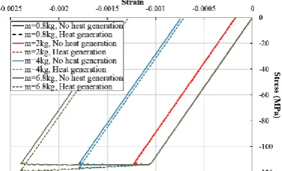
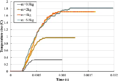
The stress-strain variations and time histories of the martensite volume fraction and temperature rise of the impacted point of the plate are depicted in Figs. 5 to 7 for various indenter masses and compared with the traditional results wherein the impact-induced heat generation is neglected. From Fig. 5 it can be deduced that the highest stress induced by the 0.8kg mass is lower than that required for the martensite phase transformation. The dissipated energy includes the whole region above each stress-strain curve. The difference percent in the dissipated energy due to neglecting the heat generation is given in Table 1, for various initial velocities and masses of the indenter. As Fig. 5 shows, more energy dissipation is expected when considering the heat generation phenomenon. Based on the results of Table1, the maximum discrepancy due to neglecting the heat generation is associated with the 6.8 kg indenter (8.7%). Comparing Figs. 6 and 7, reveals that the temperature rise variations are somewhat in relation to the time history of the resulting martensite volume fraction. As may be easily noted from Figs. 5 to 7, heat generation phenomenon leads to higher stresses but less mechanical strains (due to the resulting relaxation) and consequently, slightly less martensite volume fraction. On the other hand, as may be expected, the contact time increases with the indenter mass.
Fig. 5. Effects of the impact-induced heat generation on variations of the stresses and strains of the impacted point of the plate, for various indenter masses (V=5m/s).
Fig. 6. Effects of the impact-induced heat generation on time history of the martensite volume fraction of the impacted point of the plate, for various indenter masses (V=5m/s).
Fig. 7. Effects of the impact-induced heat generation on time history of the temperature rise of the impacted point of the plate, for various indenter masses (V=5m/s).
Table 1. The discrepancies in the dissipated energy and the resulting stress magnitude, due to neglecting the impact-induced heat generation effects.
Indenter velocity (m/s)
Indenter mass
(kg)
Difference in the dissipated energy (%)
Maximum discrepancy in the stress
(%)
5 0.8 0 0
2 0.86 0.1
4 2.73 1.9
6.8 8.73 3.9
10 0.8 1.89 1.1
2 10.17 5.1
4 52.72 9.7
6.8 40.40 11.8
30 0.8 35.65 12.9
2 28.82 24.3
4 26.93 13.2
23
4.4. Results of V=10m/s
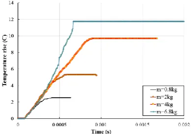
Effects of the resulting heat generation are illustrated in Figs. 8 to 10. In this case, the phase transformation occurs even for the 0.8kg indenter, but the martensite volume fraction is still below 100 percent, even for the 6.8kg indenter. As can be seen from Table 1, the discrepancies have increased by increasing the indenter velocity.
Fig. 8. Effects of the impact-induced heat generation on variations of the stresses and strains of the impacted point of the plate, for various indenter masses (V=10m/s).
Fig. 9. Effects of the impact-induced heat generation on time history of the martensite volume fraction of the impacted point of the plate, for various indenter masses (V=10m/s).
Fig. 10. Effects of the impact-induced heat generation on time history of the temperature rise of the impacted point of the plate, for various indenter masses (V=10m/s).
Lateral deflection contour at the instant of maximum contact force is illustrated in Fig. 11.
Fig. 11. Contours of the lateral deflection of the SMA composite plate, for the 6.8kg indenter.
4.5. Results of V=30 m/s
24
Fig. 12. Effects of the impact-induced heat generation on variations of the stresses and strains of the impacted point of the plate, for various indenter masses (V=30m/s).
Fig. 13. Effects of the impact-induced heat generation on time history of the martensite volume fraction of the impacted point of the plate, for various indenter masses (V=30m/s).
Fig. 14. Effects of the impact-induced heat generation on time history of the temperature rise of the impacted point of the plate, for various indenter masses (V=30m/s).
Figure 14 reveals that the temperature rise has reached up to 12℃. This amount of temperature rise cannot be neglected. However, since the material properties assumed to be temperature-independent, their effects on the global
responses have not been remarkable. This can be observed from Fig. 15 that illustrates effects of the heat generation on the contact force of the plate. On the other hand, results of Table 1 reveal that due to the nonlinear nature of the governing and contact equations, the resulting errors in the dissipated energy are case-dependent and may reach up to 52% in some cases. Therefore, when the stress distribution is uniform and nonlocal, these effects may change the results by about 20%.
Fig. 15. Effects of the impact-induced heat generation on time history of the temperature rise of the impacted point of the plate, for various indenter masses (V=30m/s, m=6.8kg).
5. Conclusions
25
extensive impact loads), the errors due to neglecting the heat generation effects may reach up to 50% in the computed dissipated energy. References
[1] S .M. R. Khalili, A. Shokuhfar, and F. Ashenai Ghasemi, “Effect of smart stiffening procedure on low-velocity impact response of smart structures”, J. Mater Proc. Tech., Vol. 190, No. 1-3, pp. 142-152, (2007).
[2] A. Shokuhfar, S. M. R. Khalili, F. Ashenai Ghasemi, K. Malekzadeh, and S. Raissi, “Analysis and optimization of smart hybrid composite plates subjected to low-velocity impact using the response surface methodology (RSM)”, Thin-Wall Struct, Vol. 46, No. 11, pp. 1204-1212, (2008).
[3] M. Meo, F. Marulo, M. Guida, and S. Russo, “Shape memory alloy hybrid composites for improved impact properties for aeronautical applications”, Compos. Struct., Vol. 95, pp.756-766, (2013).
[4] E. H. Kim, I. Lee, J. H. Roh, J. S. Bae, I. H. Choi, and K. N. Koo, “Effects of shape memory alloys on low velocity impact characteristics of composite plate”, Compos. Struct., Vol. 93, No. 11, pp. 2903-2909, (2011).
[5] J. H. Roh and J. H. Kim, “Adaptability of hybrid smart composite plate under low velocity impact”, Compos. Part B, Vol. 34, No. 2, pp.117-125, (2003).
[6] M. Shariyat and R. Jafari, “Nonlinear low-velocity impact response analysis of a radially preloaded two-directional-functionally graded circular plate: A refined contact stiffness approach”, Compos. Part B,Vol. 45, No .1, pp. 981-994, (2013).
[7] M. Shariyat and F. Farzan, “Nonlinear eccentric low-velocity impact analysis of a highly prestressed FGM rectangular plate, using a refined contact law”, Arch. Appl. Mech., Vol. 83, No .4, pp. 623-641, (2013).
[8] M. Shariyat and F. Farzan Nasab, “Low-velocity impact analysis of the hierarchical viscoelastic FGM plates, using an explicit shear-bending decomposition theory and the new DQ method”, Compos. Struct., Vol. 113, No.1, pp. 63-73, (2014).
[9] M. Shariyat and M. Moradi, “Enhanced algorithm for nonlinear impact of rectangular composite plates with SMA wires, accurately tracing the instantaneous and local phase changes”, Compos. Struct.,Vol. 108, pp. 834-847, (2014).
[10] M. Shariyat and S. H. Hosseini, “Accurate eccentric impact analysis of the preloaded SMA composite plates, based on a novel mixed-order hyperbolic global–local theory”, Compos. Struct.,Vol. 124, pp. 140-151, (2015). [11] D. Helm and P. Haupt, “Shape memory
behaviour: modeling within continuum thermo-mechanics”, Int. J. Solids Struct., Vol. 40, No. 4, pp. 827-849, (2003). [12] H. Tobushi and Y. Shimeno, T.
Hachisuka, and K. Tanaka, “Influence of strain rate on super elastic properties of TiNi shape memory alloy”, Mech. Mater., Vol. 30, No. 2, pp. 141-150, (1998).
[13] M. Kadkhodaei, RKND. Rajapakse, M. Mahzoon and M. Salimi, “Modeling of the cyclic thermo-mechanical response of SMA wires at different strain rates”, Smart Mater. Struct., Vol. 16, No. 6, pp. 2091-2101, (2007).
[14] P. C. C. Monteiro, M. A. Savi , T. A. Netto, and P. M. C. Pacheco, “A Phenomenological description of the thermo-mechanical coupling and the rate-dependent behavior of shape memory alloys”, J. Intell. Mater. Sys. Struct., Vol. 20, No. 14, pp. 1675-1687, (2009).
26
[16] J. H. Roh, “Thermomechanical Modeling of shape memory alloys with rate dependency on the pseudoelastic behavior”, Math. Prob. Eng., Vol. 20, No. 1, pp.41-65, (2014).
[17] J. Ignaczak and M. Ostoja-Starzewski,
Thermoelasticity with finite wave speeds, Oxford University Press, United States, New York, (2010).
[18] M. R. Eslami, R. B. Hetnarski, J. Ignaczak , N. Noda, N. Sumi and Y. Tanigawa, Theory of elasticity and thermal stresses, Springer, (2013). [19] L. C. Brinson, “One dimensional
constitutive behavior shape memory alloys: Thermo-mechanical derivation with non-constant material functions and redefined martensite internal variable”, J. Intell. Mater Syst. Struct., Vol. 4, No. 2, pp. 229-242, (1993).
[20] D. C. Lagoudas, Shape Memory Alloys: Modeling and Engineering Applications, Springer, (2008).
[21] J. N. Reddy, Mechanics of Laminated Composite Plates and Shells-Theory and Analysis, CRC Press, Boca Raton, (2003).
[22] V. Birman, “An approach to optimization of shape memory alloy hybrid composite plates subjected to low-velocity impact”,
Composites: Part B, Vol. 27, No. 5, pp. 439-446, (1996).
[23] J. R. Turner, “Contact on a transversely isotropic half-space, or between two transversely isotropic bodies”, Int. J. Solids Struct., Vol. 16, No. 5, pp. 409-19, (1980).
[24] A. Niknami and M. Shariyat, “Refined constitutive, bridging, and contact laws for including effects of the
impact-induced temperature rise in impact responses of composite plates with embedded SMA wires”, Thin-Walled Struct., Vol. 106, pp. 166-178, (2016). [25] S. H. Yang and C.T. Sun, “Indentation
law for composite laminates”, In: Composite materials: testing and design (6th conference), ASTM STP-787, pp. 425- 49, (1982).
[26] M. R. Eslami, Finite elements methods in mechanics, Springer, (2014).
[27] E. Serra and M. Bonaldi, “A finite element formulation for thermoelastic damping analysis”, Int. J. Numer. Meth. Eng., Vol. 78, No. 6, pp. 671-691, (2009). [28] M. Shariyat and A. Niknami, “Impact analysis of strain-rate-dependent composite plates with SMA wires in thermal environments: Proposing refined coupled thermoelasticity, constitutive, and contact models”, Compos. Struct., Vol. 136, pp. 191-120, (2016).
[29] M. Shariyat and A. Niknami, “Layerwise numerical and experimental impact analysis of temperature-dependent transversely flexible composite plates with embedded SMA wires in thermal environments”, Compos. Struct., Vol. 153, pp. 692–703, (2016).
[30] R. Tiberkak, M. Bachene, S. Rechak and B. Necib, “Damage prediction in composite plates subjected to low velocity impact”, Compos. Struct., Vol. 83, No. 1, pp.73-82, (2008).
[31] L. C. Brinson and R. Lammering, “Finite element analysis of the behavior of shape memory alloys and their applications”,
Int. J. Solids Struct., Vol. 30, No. 23, pp.3261-3280, (1993).
How to cite this paper:
A. Niknamiand M. Shariyat, “Influence of heat generation on the phase transformations and impact responses of composite plates with embedded SMA wires”, Journal of Computational and Applied Research in Mechanical Engineering, Vol. 6. No. 2, pp. 13-26
DOI: 10.22061/jcarme.2017.581
![Fig. 2. force. A comparison between present and Tiberkak et al. [30] results for the time histories of the contact](https://thumb-us.123doks.com/thumbv2/123dok_us/9967005.1984999/9.595.334.530.152.284/fig-force-comparison-present-tiberkak-results-histories-contact.webp)