Vol.7 (2017) No. 6
ISSN: 2088-5334
Implementation of Robot Operating System in Beaglebone Black
based Mobile Robot for Obstacle Avoidance Application
Mohamad Fauzi Zakaria
#, Joo Chin Shing
#, Mohd Razali Md Tomari
##
Advanced Mechatronics Research Group (AdMiRe) Faculty of Electrical and Electronic Engineering Universiti Tun Hussein Onn Malaysia (UTHM), 86400 Batu Pahat, Johor, Malaysia
E-mail: [email protected], [email protected], [email protected]
Abstract— The Robot Operating System (ROS) is a collection of tools, libraries, and conventions that focus on simplifying the task of creating a complex and advanced robotics system. Its standard framework can be shared with another robotics system that has a similar platform and suitable for being introduced as an educational tool in robotics. However, the problems found out in the current robot platform available in the market are expensive and encapsulated. The development of an open source robot platform is encouraged. Therefore, this research is carried out to design and develop an ROS based obstacle avoidance system for existing differential-wheeled mobile robot. The ROS was installed under Ubuntu 14.04 on a Beaglebone Black embedded computer system. Then, the ROS was implemented together with the obstacle avoidance system to establish the communication between program nodes. The mobile robot was then designed and developed to examine the obstacle avoidance application. The debugging process was carried out to check the obstacle avoidance system application based on the communication between nodes. This process is important in examining the message publishing and subscribing from all nodes. The obstacle avoidance mobile robot has been successfully tested where the communication between nodes was running without any problem.
Keywords— robot operating system; differential-wheeled mobile robot; beaglebone black; obstacle avoidance
I. INTRODUCTION
Mobile robotics in education is a pedagogical tool that promoting active learning and involve multi-disciplinary knowledge [1], [2]. Educators in Science, Technology, Engineering and Math (STEM) frequently choose robotics system as a subject STEM-focused problem-based learning (PBL)[3]. Therefore, the ideal features of an educational robot for a group of students are a small physical size for minimum workspace area, low power consumption, high power computational and modular configuration.
Most mobile robotics systems have similar functionalities that can be shared and used in other robots when using the same standard software framework. The current framework widely used is Robot Operating System (ROS). ROS provides standard operating system facilities such as hardware abstraction, low-level device control, implementation of commonly used functionalities, message passing between processes and package management [4], [5]. It is based on graph architecture with a centralized topology where processing takes place in nodes that may receive or post, such as multiplex sensor, actuator, control, state, planning, and navigation [6], [7].
The current implementation of ROS in mobile robotics system is using a laptop computer integrated with an
embedded controller. Their dimension is more than 30 cm x 15 cm, consequently not suitable for academic purpose especially when the testing area is limited [8]–[13]. Therefore, there is a need a small size robot to be designed that uses an embedded Linux single-board computer. This embedded Linux board is low power consumption and open source in hardware and software capabilities which fulfil the ideal features of the educational robot.
The specific objectives of this paper are to implement the ROS on embedded Linux system and to design and develop an obstacle avoidance application for the differential-wheeled mobile robot. This robot would be a teaching tool for a course of Mobile Robotics at the Faculty of Electrical and Electronic Engineering, Universiti Tun Hussein Onn Malaysia. This course covers robot perception, localization, planning and navigation that would be relied on the successful projects done by ROS community.
II. MATERIAL AND METHOD
motor is attached to the infrared sensor to detect the obstacle in three angles. (45°, 90°, and 135°). The main controller board is a Beaglebone Black Revision C, and its base operating system is Ubuntu ARM 14.04 LTS. Under this operating system, the ROS Jade version is installed.
A. System Architecture
The overall system architecture of this research is shown in Fig. 1. This system consists of three major applications that are obstacle avoidance system and motor control system. The obstacle avoidance system will continuously receive data from the infrared sensor and servo motor. These data will further be processed by the obstacle avoidance algorithm. After that, the processed information will be transferred to the motor control system to trigger the dc motors to turn to the desired direction. The motor control system is implemented to move the robot by trigger the DC motor in the forward direction or left, and right direction depends on the obstacle detected.
Fig. 1 Block diagram of system architecture
B. Hardware
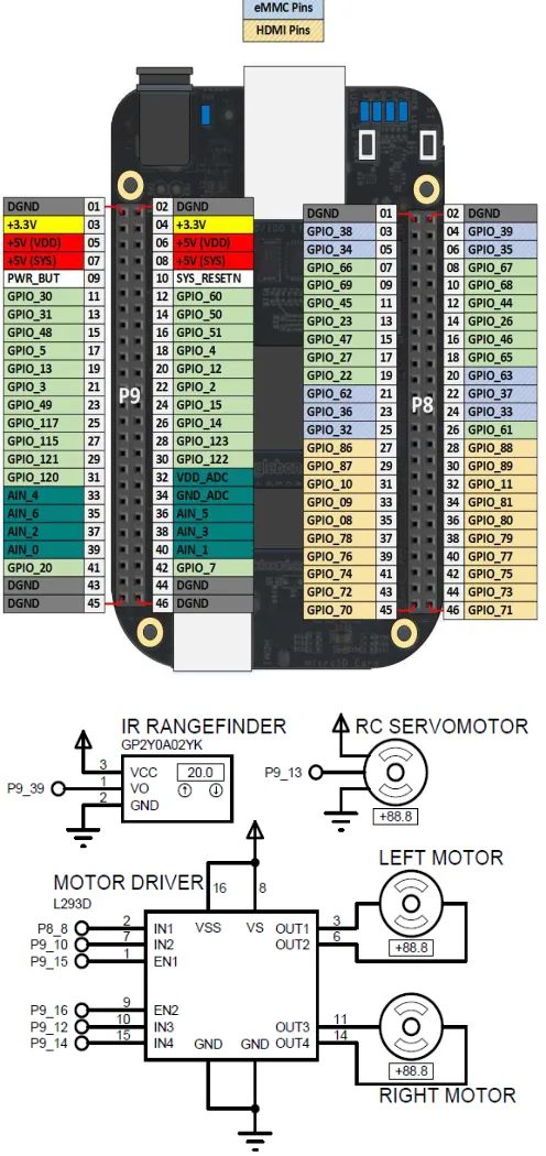
Fig. 2 shows the circuit connection of the electronics hardware interface. The infrared sensor that attached to RC Servo Motor is connected to an analog pin, AIN0 of Beaglebone Black. The position control of Servo Motor is based on pulse width modulation (PWM) signal from pin P9-P13. The Beaglebone Black control the speed and direction of two DC motors via an L293D motor driver. The power supply system has relied on a 5VDC power bank battery with maximum 2A current.
C. ROS Installation on Beaglebone Black
The Beaglebone Black is communicated through Secure Shell (SSH) in a Linux system. The command to access SSH is:
$ ssh [email protected]
After that, the system will prompt the user to enter the username and password. The default username is ubuntu, and the default password is temppwd. In order to install ROS on Beaglebone Black, the network access is necessary. The network of main OS can be shared with the OS on Beaglebone Black with the following command:
On the Beaglebone Black:
$ sudo ifconfig usb0 192.168.7.2 $ sudo route add default gw 192.168.7.1
On the main OS:
#wlan0 is the main OS internet facing interface, eth1 is the Beaglebone USB connection.
$ sudo su
$ ifconfig eth1 192.168.7.1
$ iptables –table nat –append POSTROUTING –out-interface wlan0 –j MASQUERADE
$ iptables –append FORWARD –in-interface eth1 –j ACCEPT
$ echo 1 > /proc/sys/net/ipv4/ip_forward
Fig. 2 Schematic diagram of electronics circuit
The following installation guideline is based on [6]. Step 1:
$ sudo update-locale LANG=C LANGUAGE=C LC_ALL=C LC_MESSAGES=POSIX
Step 2:
The sources.list is set up with the following command to accept software from ARM mirror on packages.ros.org:
$ sudo sh –c ‘echo “deb http://packages.ros.org/ros/ubuntu trusty main” > /etc/apt/sources.list.d/ros-latest.list’
Step 3:
Set up the keys with the command:
$ wget
https://raw.githubusercontent.com/ros/rosdistro/master/ros.k ey -O - | sudo apt-key add –
Step 4:
The ROS packages is installed with the following command:
$ sudo apt-get install ros-indgo-ros-base
Step 5:
rosdep need to be installed first to enable the installation of
system dependencies with the command:
$ sudo apt-get install python-rosdep $ sudo rosdep init
$ rosdep update
Step 6:
The ROS environment is setup with the command:
$ echo “source /opt/ros/indigo/setup.bash” >> ~/.bashrc $ source ~/.bashrc
Step 7:
Finally, after all, the requirements are set up, the ROS can be installed with the following command:
$ sudo apt-get install python-rosintall
D. ROS System Setup
First, a workspace is created as the project folder of ROS. In ROS, the developer standardizes the project folder of ROS as catkin workspace. The user can create the catkin
workspace with the following command:
$ mkdir –p ~/catkin_ws/src $ cd ~/catkin_ws/src $ catkin_init_workspace
After the workspace is created, it must be built first to insert the project folder into ROS system. This can be enabled by the following command:
$ cd ~/catkin_ws/ $ catkin_make
E. Application Software
The programming language for software development is in Python. Before the coding was written, the overall software flow-chart should be designed. As in Fig. 3, once the program is running, the robot will start moving in a forward direction when no obstacle is detected. The infrared sensor attached to the servo motor will repeatedly detect the distance in front from angle 90°→45°→90°→135°. When the distance of obstacle detected is less than 15 cm, the robot
will stop moving, and the servo motor will turn to 0° and 180° to detect the distance at 0° and 180°. If the distance at 0° is more than the distance at 180°, the motor will turn to the right (0°). On the other hand, the motor will turn to the left (180°) if the distance at 180° is more than the distance at 0°. If the distance at left and right is less than 30cm, the robot will turn backward. After that, the robot will continue to move in the forward direction until an obstacle is detected.
In Fig. 4, the motor control node consists of a program that is used to control the rotation direction of the motor. This node will continuously subscribe to the stop_moving message and turn_direction message from the sensor node and compare_distance node. Normally, if no obstacle is detected, the motor control node will control the rotation of the motor in the forward direction. If the stop_moving message is received means obstacle is detected, the motors will be stopped from rotating to stop the robot from moving. If turn_direction message is received, motors are triggered to move the robot in left or right direction depends on the message received. After the robot finished the move in a direction, the motor control node will then control the rotation of the motor to rotate in the forward direction. To start with, the node should register with the ROS Master to locate the message passing path to the destination node.
Fig. 4 Motor control system
The sensor node continuously receives data from the infrared sensor and the data received is converted into centimeter to indicate the distance detected in the current moment as shown in Fig. 5. The sensor node is always subscribed to the check message. When the check message is received, the sensor node will run the program to detect the distance obstacle in front. The distance detected is published as a distance_detected message to the servo motor node. The distance_detected message will be subscribed by servo motor node to receive current distance detected by the robot; this data will be further processed by servo motor node.
Fig. 5 Infra-red sensor block diagram
In Fig. 6, the servo motor node is responsible for control the motion of servo motor. This node will always subscribe to the distance_detected topic. Due to the limitation of the infrared sensor that is unable to detect object not perpendicular to the sensor, thus the servo motor is used together with the sensor. The sensor will always check the distance in front from the distance_detected topic in 45° to 135° with the use of servo motor; once an obstacle is detected, the sensor will check the distance of left and right. The distance detected in the direction of left and right is then published to compare distance node as a distance_right message and distance_left message. Then compare distance node will further process these two messages to decide which direction to be moved to. Moreover, this node will also publish an obstacle_detected message when an obstacle is detected in front.
The compare distance node is constructed to compare the distance at 0° and 180°. This node is continuously subscribed to two messages, distance_left message and
distance_right message. Two of this message is sent by
servo motor node when an obstacle is detected. The messages received are the distance detected at 0° and 180° which is an Int16 data type. The program of compare distance node will compare the distance received and publish a message called direction to DC motor node. If the distance at 180° is more than the distance at 0°, the
turn_right message is published. Otherwise, a turn_left
message is sent. Fig. 7 shows the block diagram for compare distance node.
Fig. 6 Servomotor block diagram
Fig. 7 Compare distance block diagram
III.RESULT AND DISCUSSION
The implementation of ROS in obstacle avoidance system is debugged based on the communication between nodes. In a ROS system, many nodes are communicating with each other for an application. roscore is a collection of nodes and programs that are pre-requisites of a ROS system. To enable communication of all the nodes, roscore must be launched. Once the roscore is launched, it will start up: a ROS Master; a ROS Parameter Server; and a rosout logging node. All the systems above are required to start up the communication between nodes. It can be terminated with keyboard interrupt to shut down the ROS system.
A. ROS Graph
Fig. 8 ROS graph
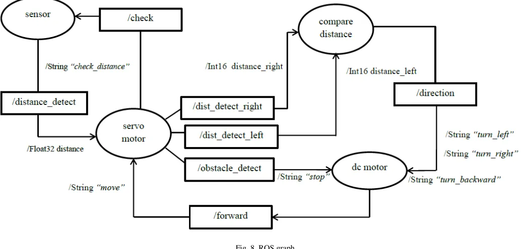
Fig. 8 shows the ROS graph for communication between four nodes. The topic distance_detect is initialized by sensor node and subscribed by servo motor node to detect the obstacle distance. Besides, the servo motor initializing three topics call dist_detect_right, dist_detect_left, and dist_detect. The topics of dist_detect_right and dist_detect_left are subscribed by compare distance node to compare the distance of left and right, and then publish a message to DC motor by through direction topic. Whereas, the dist_detect topic is subscribed by DC motor node to stop the robot from moving. The DC motor node also initializes a topic called
forward to publish a move message to servo motor node.
B. Execution of ROS Nodes
In a ROS system, many nodes are communicating with each other for an application. roscore is a collection of nodes and programs that are pre-requisites of a ROS system. To enable communication of all the nodes, roscore must be launched. Once the roscore is launched, it will start up:
• a ROS Master
• a ROS Parameter Server
• a rosout logging node
All the systems above are required to start up the communication between nodes. It can be terminated with keyboard interrupt to shut down the ROS system. Before running a roscore, the ROS must be source first to enable the access to the ROS commands and build into the workspace:
$ cd ~/catkin_workspace $ source /opt/ros/jade/setup.bash $ source devel/setup.bash
Fig. 9 and 10 show the source and roscore are run in the terminal.
Fig. 9 Source of ROS setup bash file
Fig. 10 Execution of roscore
C. Execution of Application Nodes
After the roscore is launched, the application’s program can be run by using rosrun command. In a ROS system, the program is called as a node. Most of the nodes in ROS system are required to communicate with another node to send and receive a message at that instance. Thus, all the nodes must be run so that all the features of an application can be executed. The command to run the program is:
In terminal 1:
$ rosrun ultra_class ultra_class.py
In terminal 2:
$ rosrun servo_class servo_class.py
In terminal 3:
$ rosrun compare_distance compare_distance.py
In terminal 4:
$rosrun dc_motor dc_motor.py
nodes. When the sensor node was executed, the program would not be run if the servo motor node was not executed. This is because the sensor node was always waiting for the message from the servo motor to detect the distance.
Once the servo motor was executed, communication was established, message publishing and subscribing were initiated. The programs of the sensor node and servo motor node would be executed. Figs. 11 and 12 show the communication between the sensor node and servo motor node.
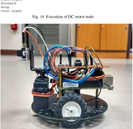
Moreover, compare distance node, and DC motor node could be executed after the sensor node, and servo motor node was executed. The compare distance node would always wait for the message published by a servo motor. Thus, the program of this node would not be run if the servo motor node was not executed. Once the compare distance node received a message from servo motor node, the direction message would be published after the distance received was compared. Thus, the DC motor node would control the DC motors depended on the message received from compare distance node. Figs. 13 and 14 show the communication between compare distance node and DC motor node. The complete prototype of mobile robot system was successfully built and tested as shown in Fig. 15.
Fig. 11 Execution of sensor node
Fig. 12 Execution of servomotor node
Fig. 13 Execution of distance comparison node
Fig. 14 Execution of DC motor node
Fig. 15 Side view of complete prototype
IV.CONCLUSIONS
As a conclusion, Robot Operating System (ROS) is a system designed for the development of a robotic system. The system is an open source where the robotic researchers or engineers can share their idea or system to the public in terms of source code, system design or hardware design. Moreover, the information shared was kept on maintained by the engineer which the engineer will continuously update their system. The objective of the research is achieved by integrating the ROS on the mobile robot designed. The obstacle avoidance mobile robot is successfully designed based on the ROS where the communication between the programs is successfully integrated. Besides, the performance of the robot is fast and smooth which the delay of communication between programs is approximately in a millisecond. Thus, the Beaglebone Black based mobile robot that equipped with ROS is recommended as a teaching tool for mobile robotics course.
thin object. Thus, a webcam is attached to the mobile robot so that the current image can be processed by a vision system.
ACKNOWLEDGMENT
The authors would like to thank the Office of Research, Innovation, Commercialization and Consultancy (ORICC), Universiti Tun Hussein Onn Malaysia (UTHM) for the funding of this paper publication.
REFERENCES
[1] S. F. R. Alves, H. F. Filho, R. Pegoraro, M. A. C. Caldeira, J. M. Rosário, and W. M. Yonezawa, “Proposal of educational environments with mobile robots,” in 2011 IEEE 5th International
Conference on Robotics, Automation and Mechatronics (RAM), 2011,
pp. 264–269.
[2] M. Beschi, R. Adamini, A. Marini, and A. Visioli, “Using of the Robotic Operating System for PID control education,” IFAC-Pap., vol. 48, no. 29, pp. 87–92, Jan. 2015.
[3] C. Vandevelde, F. Wyffels, M.-C. Ciocci, B. Vanderborght, and J. Saldien, “Design and evaluation of a DIY construction system for educational robot kits,” Int. J. Technol. Des. Educ., vol. 26, no. 4, pp. 521–540, Nov. 2016.
[4] “About ROS.” [Online]. Available: http://www.ros.org/about-ros/. [Accessed: 26-Mar-2017].
[5] A. Koubaa, Robot Operating System (ROS): The Complete Reference. Springer, 2016.
[6] Enrique Fernández, L. Sánchez Crespo, A. Mahtani, and A. Martinez,
Learning ROS for Robotics Programming. Packt Publishing Ltd,
2015.
[7] L. Garber, “Robot OS: A New Day for Robot Design,” Computer, vol. 46, no. 12, pp. 16–20, Dec. 2013.
[8] E. Ruiz, R. Acuña, N. Certad, A. Terrones, and M. E. Cabrera, “Development of a Control Platform for the Mobile Robot Roomba Using ROS and a Kinect Sensor,” in 2013 Latin American Robotics
Symposium and Competition, 2013, pp. 55–60.
[9] E. M. H. Zahugi, A. M. Shabani, and T. V. Prasad, “Libot: Design of a low cost mobile robot for outdoor swarm robotics,” in 2012 IEEE
International Conference on Cyber Technology in Automation, Control, and Intelligent Systems (CYBER), 2012, pp. 342–347.
[10] V. Bayar, B. Akar, U. Yayan, H. S. Yavuz, and A. Yazici, “Fuzzy logic based design of classical behaviors for mobile robots in ROS middleware,” in 2014 IEEE International Symposium on Innovations
in Intelligent Systems and Applications (INISTA) Proceedings, 2014,
pp. 162–169.
[11] A. Araújo, D. Portugal, M. S. Couceiro, and R. P. Rocha, “Integrating Arduino-Based Educational Mobile Robots in ROS,” J.
Intell. Robot. Syst., pp. 1–18, Feb. 2014.
[12] G. Fu and X. Zhang, “ROSBOT: A low-cost autonomous social robot,” in 2015 IEEE International Conference on Advanced
Intelligent Mechatronics (AIM), 2015, pp. 1789–1794.
[13] H. I. M. A. Omara and K. S. M. Sahari, “Indoor mapping using kinect and ROS,” in 2015 International Symposium on Agents,
Multi-Agent Systems and Robotics (ISAMSR), 2015, pp. 110–116.
[14] M. Quigley, B. Gerkey, and W. D. Smart, Programming Robots with
ROS: A Practical Introduction to the Robot Operating System.