Behaviour Of Lateral Resistance Of Flexible Piles In Layered Soils
PERIYASAMI.T.K
PG Student, Department of Civil Engineering, PRIST University, Thanjavur, Tamil Nadu, India.
ABSTRACT
Piles are structural members that are made of steel, concrete or timber. They are used to build deep foundations and which cost more than shallow foundations. Despite the cost, the use of pile is often necessary to ensure structural safety. Some time piles are subjected to lateral load. For example piles in Quay and Harbor structure. Offshore structures have been built for oil production and for many other reasons in many parts of the world. Their design involves the consideration of unusually large ratios of lateral load to vertical load, particularly in areas where severe storms occur. The exact effect of the cyclic wave loading on the soil response conducted in analytical fashion is very complex. It would be unrealistic to precisely follow in continuous fashion the path of this response. The sources of lateral load on harbor structure are impact of ship and wave action and off shore structures are also subjected to wind and wave. High rise building, tower are subjected to lateral load due to wind and earthquake forces. So it is important to know the lateral load resistance capacity of pile foundation. A key element in the design of laterally loaded piles is the determination of ultimate lateral resistance that can be exerted by the soil against the pile (Murff and Hamilton 1993). For example, the ultimate lateral resistance is required for calculating p-y curves, which are used in the analysis of piles. Several methods have been published for predicting the ultimate lateral resistance to piles in cohesion less soils (Brinch Hansen 1961; Broms 1964; Reese et al. 1974; Poulos and Davis 1980; Fleming et al. 1992). However these methods often produce significantly different ultimate resistance values. This makes it difficult for practicing engineers to effectively select the appropriate method when designing the laterally loaded piles in cohesion less soils. In this thesis work lateral load carrying capacity of piles are calculated as per IS 2911 and the results obtained was compared with Broms method.
KEYWORDS: Pile, Cohesionless soil, Lateral load, Broms method, Finite Element Analysis.
INTRODUCTION
Pile foundations are often necessary to support large structures when the surface soil conditions are not strong enough to
support the structure with shallow
foundations. Pile foundation can be founded in dense sand layers at depth, and also provide additional frictional support along
Piles subjected to horizontal load due to wind pressure, water pressure, earth pressure, earth quakes, wave and current forces on offshore structures are termed as laterally loaded piles. The performance of pile foundations subject to lateral load is of considerable importance in geotechnical practice. Pile foundations are usually used when heavy super-structural loads have to be transmitted through weaker subsoil. Pile foundations may be required to resist
significant lateral forces induced by
earthquakes, winds, waves, earth pressures and ship impacts. In marine structures, lateral forces are caused by impact of berthing and mooring of ships, pressure of winds, currents, waves and floating ice. Piles are also subjected to significant amounts of lateral loads and overturning moments besides axial loads when used under tall chimneys, high-rise structures, and coastal and offshore structures. Piles are also designed for lateral loads, when they are required to restrain forces causing sliding or overturning of structures. Lateral loads are in the order of 10-15% of the vertical loads in the case of onshore structures, and in the case of coastal and offshore structures, these lateral loads can exceed 30% of the vertical loads.
Therefore, proper attention has to be given in designing such pile structures under lateral loads.
The governing criterion in designing pile foundations to resist lateral loads in most cases is the maximum deflection and moment of the piles rather than its ultimate capacity. The maximum deflection at the pile head and the distribution of the bending moment along the pile are important
information for the successful design of pile foundations that support lateral loads. The maximum moment in a pile and the depth at which it occurs depend on the stiffness of the pile-soil system and the loading conditions. Pile overstress will occur if the moment exceeds the allowable moment of the pile materials.
OBJECTIVES
The objectives of this paper were
(a) To find the lateral and vertical load carrying capacity of single pile in sandy soil. (b) To compare the load carrying capacity of pile by IS 2911 part 1(sec 2) with Broms method.
(c) To find the effect of diameter of the pile on lateral load capacity.
(d) To find the effect of length of the pile on lateral load capacity.
METHODOLOGY
The various methods employed in this paper were discussed with the results in the following topics.
Effect of Diameter of the Pile on Lateral Load Capacity
Part1 (sec2) was significantly less when compared with Broms method.
Effect of Length of the Pile on Lateral Load Capacity
To study the effect of length of the pile on lateral load capacity, 0.50 m diameter piles of different lengths such as 8 m, 8.9 m, 10 m, 11.4 m, 13.3 m, 16 m, and 20 m were considered. The results are presented in Table 3 and 4, which indicated that the axial
load capacity increases with increasing length of the pile. This was due to that the
friction was mobilized on increased
embedment of pile. But there was no much variation in moment and lateral load capacity. The lateral load capacity of pile obtained from IS 2911 Part1 (sec2) was significantly less when compared with
Broms method.
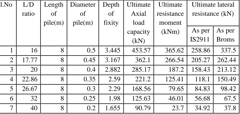
Table: 1 Comparison of lateral load resistance capacity of fixed head pile by IS 2911 part 1(sec 2) and Broms Method for variable diameter of piles
Sl.No L/D
ratio
Length of pile(m)
Diameter of pile(m)
Depth of fixity
Ultimate Axial
load capacity
(kN)
Ultimate resistance
moment (kNm)
Ultimate lateral resistance (kN)
As per IS2911
As per Broms
1 16 8 0.5 3.445 453.57 365.62 258.86 337.5
2 17.77 8 0.45 3.167 362.1 266.54 205.27 262.44
3 20 8 0.4 2.882 285.17 187.2 158.43 213.12
4 22.86 8 0.35 2.59 221.2 125.41 118.1 150.49
5 26.67 8 0.3 2.29 168.56 79.65 84.83 98.42
6 32 8 0.25 1.98 125.63 46.01 56.68 67.5
7 40 8 0.2 1.655 90.79 23.7 34.92 37.8
Table: 2 Comparison of Lateral deflection at ground level for fixed head pile by IS 2911 part 1(sec 2) and Broms Method for variable diameter of piles
Sl.No L/D
ratio
Ultimate lateral resistance (kN)
Lateral deflection at ground level (mm)
As per IS2911
As per Broms
1 16 258.86 11.5 13.61
2 17.77 205.27 10.8 13.2
3 20 158.43 10.06 12.8
4 22.86 118.1 9.28 12.42
5 26.67 84.83 8.54 11.78
7 40 34.92 6.72 8.69
Table: 3 Comparison of lateral load resistance capacity of fixed head pile by IS 2911 part 1(sec 2) and Broms Method for variable length of piles
Sl.No L/D
ratio
Length of pile(m)
Diameter of pile(m)
Depth of fixity
Ultimate Axial
load capacity
(kN)
Ultimate resistance
moment (kNm)
Ultimate lateral resistance (kN) As per
IS2911
As per Broms
1 16 8 0.5 3.445 453.57 365.62 258.86 337.5
2 17.77 8.9 0.5 3.445 497.25 368.75 261.08 343.13
3 20 10 0.5 3.445 556.98 369.84 261.85 348.75
4 22.86 11.4 0.5 3.445 643.02 370.94 262.63 354.38
5 26.67 13.3 0.5 3.445 778.97 371.88 263.29 360
6 32 16 0.5 3.445 1005 362.5 256.65 337.5
7 40 20 0.5 3.445 1418.65 343.75 243.38 331.88
Table: 4 Comparison of Lateral deflection at ground level for fixed head pile by IS 2911 part 1(sec 2) and Broms Method for variable length of piles
Sl.No L/D
ratio
Ultimate lateral resistance
(kN)
Lateral deflection at ground level
(mm) As per IS2911
As per Broms
1 16 258.86 11.5 13.61
2 17.77 261.08 11.59 14.13
3 20 261.85 11.63 14.63
4 22.86 262.63 11.67 14.76
6 32 256.65 11.4 14.45
CONCLUSIONS
From the obtained data the following conclusions were made:
1. The effect of pile length was studied and it was concluded that axial load capacity increases with increase in length of the pile. This was because of the friction was mobilized on increased embedment of pile 2. The effect of pile diameter was studied and it was concluded that lateral load capacity increases with increase in diameter of the pile for same length. This was due to the increase in surface area, pile stiffness, moment of inertia and young’s modulus. 3. The lateral load capacity of pile obtained from IS 2911 Part1 (sec2) was significantly less when compared with Broms method.
REFERENCES
1 Braja M.Das (2005)”Principles of
foundation Engineering” Thomson Asia private limited.
2 Broms, B. (1964a) “the Lateral
Resistance of Piles in Cohesive
Soils,” J. Soil Mech. Found. Div.,
ASCE, Vol. 90, pp. 27-63.
3. Budhu, M. & Davis, T. G. (1988)
“Analysis of Laterally Loaded Piles
in Soft Clays,” J. Geotechnical
Engineering, ASCE, Vol. 114, No.1, pp. 21-39.
4. Matlock, H. and Reese, L. C. (1962)
“Generalized Solutions for Laterally Loaded Piles,” Transactions of the
American Society of Civil
Engineers, Vol. 127, part 1, pp. 1220-1247.
5. P.C.Varghese (2010)”Foundation
Engineering” PHI Learning private limited
6. Pise, P. J. (1983) “Lateral Response
of Free-Head Pile,” J. Geotechnical
Engineering, Vol. 109, No.8, pp.
1126-1131.
7. Poulos, H.G. (1971a) “Behavior of
Laterally Loaded Piles: I-Single
Piles,” J. Soil Mech. Found. Div.,
ASCE, Vol. 97, No. SM 5, pp.
711-731.
8. Poulos, H.G. and Davis, E. H. (1980)
“Pile Foundation Analysis and Design,” John Wiley & Sons, New York.
9. Reese, L. C. (1977) “Laterally
Loaded Piles: Program
documentation,” J.Geotech. Eng.
Div., ASCE, Vol. 103, No. GT4, pp.
287-305.
10.Reese, L. C. and Van Impe, W. F.