Development and Analysis of Finned Brake
Drum Model Using Solidworks Simulation
Bako Sunday
1, Usman Aminu
2, Paul O. Yahaya
3, , Mohammed B. Ndaliman
4Lecturer, Department of Mechanical Engineering, Nuhu Bamalli Polytechnic Zaria, Nigeria1 Lecturer, Department of Mechanical Engineering, Nuhu Bamalli Polytechnic Zaria, Nigeria2 Senior Instructor, Department of Mechanical Engineering, Nuhu Bamalli Polytechnic Zaria, Nigeria3 Associate Professor, Department of Mechanical Engineering, Federal University of Technology Minna, Nigeria4
ABSTRACT: A brake is a friction device for converting the power of momentum or kinetic energy of a moving vehicle into heat energy by means of friction, thereby decelerating the motion of the vehicle. The heat energy is to be dissipated rapidly in order to control brake fade and brake failure. This can be subdue on brake drums, by providing cooling fins (extended surface) on the outer surface of the brake drums. This paper presents the development and analysis of a modified brake drum model having extended surface (fins) along its circumference. The fins or extended surface are designed to improve the heat dissipation rate from the surface of the brake drums which are convectively cooled by the streams of air flowing on its outer surface. One-fourth of the overall height thickness of the original brake drum model was converted into fins. The simulation carried out on the original and the modified models, shows that the modified brake drum model has a higher circumferential strength and better heat dissipation than the original brake drum model.
KEYWORDS: Brake Drum Development and Analysis.
I. INTRODUCTION
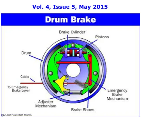
The brakes are energy conversion system which converts the kinetic energy of a moving vehicle into thermal energy. The systems are designed to decelerate the vehicle wheels movement through friction, thereby absorbing the kinetic energy at the wheels. The drum brakes are mainly used at the rear wheels of the passengers’ cars and truck while the disc brakes are extremely used for the front bakes because of their greater directional stability. In brake drum, friction is caused by a set of shoes that presses against the inner surface of a rotating brake drum. Within the drum are shoes lined with friction material. The brake shoes moves against the inner surface of the brake drum by the action of the piston inside the wheel cylinder. The hydraulic fluid under pressure in the wheel cylinder moves the pistons which forces the brake shoes against the brake drum. The wheel cylinder and the shoes are mounted on the back plate.
Fig 1. Drum Brake Assembly (Karim 2015)
II. MATERIALS AND METHODS
The materials used in this analysis include; solidworks (2913) package, an original and a modified brake drum model developed with the help of Kicreyco brake drum catalogue. The properties of the brake drum material (gray cast iron) are shown in table 2 below. In the analysis, solidworks modelling and simulation methodology has been employed to develop and study the impact of forces and thermal stress acting on the original and modified brake drum model.
A. Properties of the Brake Drum
1. Must have a hard wear-resistant rubbing surface and surface finish must not damage the lining. 2. Must be strong enough to withstand the hardest braking while at high temperature.
3. Must be stiff and resistant to distortion and warping
4. Must dissipate heat rapidly and withstand excessive temperature.
B. Brake Drum Nomenclature
1. A-Overall Diameter
2. B-Dust Shield Recess Diameter/ Outer Diameter 3. C-Brake Face Diameter/ Inside Diameter 4. D-Brake Face Width
5. E-Overall Height
6. F-Squealer Band Thickness 7. G-Depth of Dust Shield Recess 8. H-Hub Pilot
9. I-Bolt Hole Diameter/Number 10. J-Bolt Circle Diameter.
III. BRAKE DRUM DEVELOPMENT
In this paper, one-fourth of the overall height thickness of an original brake drum model was converted into extended surface. The modified brake drum model was developed in such a way to maintain the same mass as the original model, but to exhibit better brake drum properties than the original model.
A. To Calculate the Fins Spacing s,
For the purpose of this paper, the distance between the fins s, is considered to be twice the thickness (t) of the fins,
Thus 𝑠 = 2𝑡 (1)
The brake drum is design to have the fin thickness (t) of 10mm. 𝑡 = 10𝑚𝑚
𝑠 = 2 × 10 = 20𝑚𝑚
Therefore the fins are 20mm apart,
B. To Calculate the Number of Fins N, on the Modified Brake Drum Model
The number of fins (N) round the circumference of the brake drum is given by;
𝑁 = 𝑊
𝑡 + 𝑠 (2) Where W = fins Width.
For the purpose of this design the fin width is considered as the width of the brake shoe acting on the surface of the brake drum.
W = 180mm
𝑁 = 180
10 + 20=
180 30 𝑁 = 6
Therefore 6 fins are to be developed on the outer surface of the modified brake drum model.
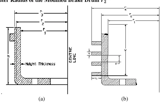
C. To Calculate the Outer Radius of the Modified Brake Drum 𝒓𝟐
.
(a) (b)
Fig 3. (a). A Section of the Original Model, (b). A Section of the Modified Model
Since the overall height thickness of the original brake drum is reduce by one-fourth (1/4) of its original size. Therefore the new outer radius 𝑟2 is given by;
𝑟2= 𝑟3− (
𝑟3− 𝑟1
4 )
𝑟2=
3𝑟3+ 𝑟1
Where, 𝑟1= Brake face diameter = 230mm
𝑟3= Dust shield recess diameter/ outer diameter = 240mm
𝑟2=
3 × 240 + 230
4 = 238𝑚𝑚
𝑟2= 238𝑚𝑚
Therefore the outer radius of the proposed brake drum is 238mm
D. To Calculate the Radius of the Fins 𝒓𝟒
To determine the value of 𝑟4, we find the volume 𝑉1, of the brake drum that is deducted from the original model. The
volume 𝑉1 is given by;
𝑉1= 𝜋 𝑟32− 𝑟22 ℎ (4)
Where, h = Overall Brake drum height = 210mm. The volume of one circular fin 𝑉𝑓 is given by;
𝑉𝑓= 𝜋 𝑟42− 𝑟22 𝑡
Where t = Fin thickness.
The total volume of the 6 fins 𝑉6𝑓 is given by;
𝑉6𝑓= 6𝜋 𝑟42− 𝑟22 𝑡 (5)
Since this design involves converting the volume 𝑉1 into extended surface (fins) of equal volume 𝑉6𝑓. Therefore the
volume 𝑉1 deducted from the original model is equal to total volume of the fins 𝑉6𝑡. Thus,
𝜋 𝑟32− 𝑟22 ℎ = 6𝜋 𝑟42− 𝑟22 𝑡
𝑟42− 𝑟22=
𝜋 𝑟32− 𝑟22 ℎ
6𝜋𝑡
𝑟4= 𝑟32−𝑟
22 ℎ
6𝑡 + 𝑟2
2 (6)
𝑟4=
(2402− 2382)210
6 × 10 + 238
2
𝑟4= 245𝑚𝑚
Therefore the fins have the outer radius of 245mm from the centre of the brake drum.
E. To Calculate the Length of the Fins L
The length of the fins L, is given by;
𝐿 = 𝑟4− 𝑟2 (7)
𝐿 = 245 − 238 = 7𝑚𝑚
The length of the fin is 7mm from the dust shield recess radius/ outer radius
F. To Calculate the Total Surface Area of the Fins Afin
𝐴𝑓𝑖𝑛 = 2𝜋 𝑟42− 𝑟22 + 2𝜋𝑟4𝑡 (8)
𝐴𝑓𝑖𝑛 = 2 × 3.142 2452− 2382 + 2 × 3.142 × 245 × 10
𝐴𝑓𝑖𝑛 = 36642𝑚𝑚2
The total surface area of the six fins = 6 × 366542219852𝑚𝑚2
This is the total surface area added to the outer surface of the brake drum for heat dissipation.
IV. BRAKE DRUM MODELLING
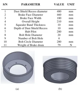
The modified brake drum model has 6 fins of 10mm thickness and 7mm length; the two models are shown in figure 4. The brake drum models have the following specification.
Table 1. Models Specification
S/N PARAMETER VALUE UNIT
1 2
Dust Shield Recess diameter Brake Face Diameter
480 460
mm mm
3 Brake Face Width 180 mm
4 Overall Height 210 mm
5 Squealer Band Thickness 10 mm
6 Depth of Dust Shield Recess 10 mm
7 Hub Pilot 280 mm
8 Bolt Hole Diameter 20 mm
9 Number of Bolt Hole 6
10 Bolt Circle Diameter 280 mm
11 Weight of Brake drum 79 N
(a) (b)
Fig 4. (a). Original Model, (b). Modified Model
V. SIMULATION AND ANALYSIS
.
In acceleration, heat energy of the fuel is converted by the engine into kinetic energy to move the vehicle. In braking, the kinetic energy is converted into heat by means of friction produced between the two mating surface of the brake drum. The amount of friction developed between the two surfaces in contact is independent of the area of the surface in contact. However the magnitude of the force of friction or retarding force created between the brake lining and the brake drum depends upon the pressure or force exerted on the shoes by the retarding mechanism and the coefficient for the two materials (Narang 1977). For the purpose of this paper, a retarding force of 150N was considered to be acting between the brake lining and the brake drum.
Since the brake shoes lining are poor conductor of heat, most of the heat remains inside the brake drum during braking. Under severe condition, brake drum may reach 590K temperature (Giri 2012). This is also because lining covers a large portion of the inner surface of the brake drum, so that a little cooling space is available. This shows that the inner surfaces of the brake drums are exposed to intense heating. This heat needs to be dissipated rapidly to prevent brake failure.
Table 2. Material Specifications and Properties
S/N PROPERTY VALUE UNIT
1 Elastic Modulus 6.61781e+010 N/m2
2 Poissons Ratio 0.27 N/A
3 Shear Modulus 5e+010 N/m2
4 Density 7200 Kg/m2
5 Tensile Strength 15165800 N/m2
6 Compressive Strength 578572165000 N/m2
7 Thermal Expansion Coefficient 1.2e-005 /K
8 Thermal Conductivity 45 W/mK
9 Specific Heat 510 Kg.K
10 Brake Shoe Force 150 N
11 Brake Drum Exterior Temperature 20 C
12 Brake Drum Interior Temperature 120 C
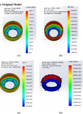
A. Analysis Results of the Original Model
(a) (b)
.
(a) (b)
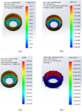
B. Analysis Results of the Modified Model
.
(a) (b)
(a) (b)
Fig 6. (a). Stress Plot for Modified Model, (b). Displacement Plot for Modified Model, (c). Strain Plot for Modified Model, (d). Thermal Plot for Modified Model
VI. DISCUSSION OF RESULTS
It was observed from the thermal analysis, that the initial temperatures of the two models are the same, but the original model shows a lower rate of decreasing in temperature than the modified model. This indicates that the rate of heat transfer is lower in the original model than in the modified model. Therefore some amounts of heat energy are retained inside the original brake drum as the result of the low heat removal from the inner surface to the outer surface of the brake drum. This retained heat energy is the major causes of brake fade and drum brake damages in the drum brake system.
The higher rate of change in temperature of the modified model from the maximum to the minimum temperature shows that the modified model has a higher rate of heat transfer compared to the original model; therefore much heat is removed from the inner surface to the outer surface of the brake drum at a faster rate. Also the minimum temperature of the modified model is higher than the minimum temperature of the original model. This shows that much heat is available at the outer surface of the modified model for heat dissipation by the action of the moving air stream on the outer surface of the brake drum. This indicates that the fins (extended surface) have improved the rate of heat dissipation and conductivity from the inner surface to the outer surface of the modified brake drum.
VII. CONCLUSIONS
By comparing the simulation results of the two brake drum models, the following conclusions were drawn;
1. The small von mises stress and displacement shown by the modified model; indicates that the modified model is stronger and rigid than the original model. With equal mass as the original model, the modified model has higher circumferential strength. This is due to the circumferential arrangement of the fins round the outer wall of the brake drum. Therefore the last three (2-4) properties of the brake drum (stated above) have been improved.
2. The high temperature of the outer surface of the modified model shows that more heat is transferred and dissipated from the brake drum. This is enhanced by the extended surface (fins) on the surface of the brake drum. Therefore the conversion of one-fourth of the overall height thickness of the original model to fins (extended surface) has also improved the heat dissipation of the modified brake drum.
However, this simulation shows that the drum brakes are prone to structural and thermal failure due to hard braking force, if the detailed design and material properties are not correctly specified. This analysis can assist Automotive Engineers to design a more effective and reliable brake drums.
REFERENCES
[1]. Anup Kumar and R. saharish. Structural and Thermal Analysis of Brake Deum. Middle East Journal of Scientific Research Vol20. (8). IDOSI Publication. Pp 1012-1016. . 2014.
[2]. Brake Drum. Available at en.wikipedia.org/wiki/Drum_brake. Cited March 2015.
[3]. Frank Kreith. Mechanical Engineerimg Handle Book. Boca Raton: CRC Press LLC. Pp 4-7. 1999.
[4]. Daniel Dannelley, John Baker, Clark K. Midkeff, Robert P. Taylor, Keith A. Woodburry. Enhancement of Extended Surface Heat Transfer Using Fractal-like Geometry. Department of mechanical Engineering, Graduate School of the University of Alabama. Pp 14-15. 2013. [5]. Fred Puhn. Brake Handbook. 2rd edition.HP Books Pp4, 15-21. 1985.
[6]. Giri N.K. Automobile Technology. Sixth edition (reprint). Khanna Publisher. Pp 1269-1272.2012.
[7]. James Carvill. Mechanical Engineer’s Data Handbook. First Edition. Butterworth Heinemann Publication. Pp129-131.1993.
[8]. Karim Nice. How Drum Brakes Works. Available at www.howstuffworks.com/auto-parts/brake/brake-types/drum-brake 1.htm. cited March 2015
[9]. Kicreyco Brake Drum Catalog. Kic Holding Inc Pp 1-12. Available at www.kic-group.com. Cited April 2015. [10]. Narang G.B.S. Automobile Engineering. First Edition. Kahanna Publisher. Pp 275-277. 1977.