IJEDR1403010
International Journal of Engineering Development and Research (www.ijedr.org)2948
Performance Analysis of Transmit Diversity and
Spatial Multiplexing MIMO modes Vs. SISO System
in LTE-Downlink System
1
Bhavesh Patel,
2Prof. Jaydeep Gheewala
1M.E., 2M.Tech.1
Computer Department
1Sarvajanik College of Engineering and Technology, Surat, Gujarat, India
______________________________________________________________________________________________________
Abstract - In this paper we evaluate the performance of LTE-Downlink System with different Transmit diversity and Spatial multiplexing MIMO modes in LTE-downlink. Here we analysis performance on BLER-Block Error Rate and Data Throughput vs SNR-Signal to Noise Ratio. Two Transmit Diversity schemes Space Frequency Block Codes (SFBC) and Frequency Switched Transmit Diversity (FSTD) and two Spatial Multiplexing with different antenns are used. The performance of LTE compared with four MIMO and SISO modes in terms of Throughput and BLER. Also we used the ITU defined Pedestrian channel type B for evaluation.
Index Terms - LTE-Downlink, MIMO modes. Throughput, Block Error Rate
______________________________________________________________________________________________________
I. INTRODUCTION
The LTE-Long Term Evolution is the latest developed and most popular standard in wireless communication system. LTE is apart of the UMTS standards but also has many changes and improvement to previous 3GPP consortium. The goal of LTE is to increase the data throughput and the speed of wireless data using a combination of new methods and technologies like OFDM and MIMO technics. The LTE downlink transmission is based on Orthogonal Frequency Division Multiple Access (OFDMA). OFDM is a technique of encoding digital data on multiple carrier frequencies and it is known to be efficient to improve the spectral efficiency of wireless system. Another important advantage of OFDM technique is to be more resistant to frequency selective fading than single carrier system by converting the wide-band frequency selective channel into a set of many flat fading subchannels. In order to optimize the system data throughput and the coverage area for a given transmission power, LTE make use of the Adaptive Modulation and Coding (AMC). In AMC, the transmitter should assign the data rate for each user depending on the channel quality from the serving cell, the interference level from other cells, and the noise level at the receiver. In terms of data throughput and reliability, the MIMO system used. MIMO was very good technique to improve the performance of wireless communication systems. Mainly MIMO modes used as Transmit diversity and Spatial Multiplexing mode. In diversity mode, the same signal is transmitted over multiple antenna and hence the its improves system reliability of the system by diversity gain. In diversity mode is mode no 2 in LTE simulator which has mapping function of each symbol to transmit antenna is called Space Time Block Code (STBC). In Spatial Multiplexing mode ,two different spatial strems are sent from two different antenns and hence the data rate is improved.
To study LTE performance we choose open source MATLAB based downlink level LTE simulator [1] [2] for analysis of research. A system level simulation [3] also developed for performance analysis in LTE system. The main feature of simulator are adaptive coding and modulation, MIMO modes transmission and scheduling. The simulator also used for different physical layer evaluation and we also study the channel estimation of OFDM systems and the performance evaluation of a fast fading channel estimator was presented. In [5] [6] a method for calculationg the precoding matrix indicator (PMI), and the Rank Indicator (RI) and the Channel Quality Indicator (CQI) were studied and analyzed with simulator.
In this paper , the BLER and the Data Throughput of SISO and MIMO modes were evaluated in 5 MHz LTE Downlink system for CQI value fixed to 7 so that corresponding Modulation and Coding Scheme (MCS) are investigated in terms of SNR using the Link Level LTE simulator [1] [2].
The remainder of this paper is oprganised as follows. In Section II, we present system and channel modes that is used in the simulation. In Section III, we present the MIMO Schemes as defined in LTE. A brief of Transmit Diversity and Spatial Multiplexing scheme is described in this section. The simulation results and discussion of presented results will be shown in Section IV. Finally , we conclude our paper analysis in Section V.
II. SYSTEMANDCHANNELMATHEMATICALMODEL
IJEDR1403010
International Journal of Engineering Development and Research (www.ijedr.org)2949
technique converts the LTE wide band signal into nos. of narrowband subcarriers. Each narrowband subcarriers is fixed to 15 KHz spacing. So total tweleve adjacent subcarriers occupying a total 180 KHz, one slot is called Resource Blocks. In LTE slot depends on the allowed system bandwidth very from 1.4 MHz to 20MHz and according to resource blocks are 6 to 100.In MIMO system with MR receive antenna and MT transmit antenna, the relation between the received and the transmiited signals on subcarrier frequency k (k ∈ 1…K), at sampling instant time n (n ∈ 1…N) is given by
, , , , ,
k n
k n k n
k ny
H
X
n
(1)
Yk,n ∈ CMRx1 is the received vector, Hk,n ∈ CMRxMT represents the channel matrix on subcarrier k at instant time n, X k,n ∈ CMTx1 is the transmit symbol vector and noise vector n k,n ~ CN(0,
2 n
.I) is white , complex valued Gaussian vector with variance
2 n
. Assuming perfect channel estimation , the channel matrix and noise variance are considered to be known at the receiver. A linear equalizer filter given by a matrix Fk,n ∈ CMTxMR is applied on the received symbol vector y k,n to determine the post –equalization symbol verctor rk,n [6]
, , , , , , , ,
k n
k ny
k n
k n k n k n
k n k nr
F
F H x
F n
(2)
The Zero forcing (ZF) or Minimum Mean Square Error (MMSE) design criterion [7] are typically used for the linear receiver and the input signal vector is normalized to unit power. In MIMO-OFDM systems, the key factor of the link error predication and performance is the signal to noise ratio (SNR) which represents the measurements for the channel quality information. In practice there are different measure for calculating SNR in SISO and MIMO system but here we consider the below equation for SNR calculation [1]:
2
, ,
, 2 2 2
||
k n k n||
F R1
k nR n R n n
X
N
y
N
N
H
(3)III. MIMO MODES IN LTE SYSTEM
In MIMO system has most popular two modes that are utilized in our LTE analysis which are Transmit Diversity mode and Spatial Multiplexing modes. Diversity modes can be used in the receive Diversity or Transmit Diversity side. Where in receive Diversity side is simply combining operation of different replicas of the same transmitted signal, Transmit Diversity requires Space Time Coding operation of different transmitted signals. In LTE Transmit Diversity modes are defined as below.
A.Transmit Diversity Modes
The Transmit Diversity techniques where are only transmitted signal replicas to minimize error rate in the receiver side. Transmit Diversity with 2 transmitter side antennas and one receiver side antenna with one data stream is defined as below codes.
When two eNodeB antennas are availabal for transmit diversity operation is called Space Frequency Block coding (SFBC) [8]. SFBC is based on Space Time Block Coding popularly known is Alamouti codes [9]. STBC is defined in the UMTS and it operates on pairs of adjacent symbols in the time domain. As the signalin LTE is two dimensional (time and frequency domains) and the number of OFDM symbols are not in even number so direct application of STBC is not straightforward. In LTE for SFBC transmission, the symbols are transmitted from two eNodeB antenna ports on each pair of adjacent subcarriers as follows [8].
(0) (0)
1 2
* *
(1) (1)
2 1
(1)
(2)
(1)
(2)
x
x
y
y
x
x
y
y
(4)Where
y
( )p( )
k
denotes the symbols transmitted on the kth subcarrier from antenna port p.IJEDR1403010
International Journal of Engineering Development and Research (www.ijedr.org)2950
(0) (0) (0) (0)(0) (0) (0) (0)
(0) (0) (0) (0)
(0) (0) (0) (0)
1 2
3 4 * *
2 1
* * 4 3
(1)
(1)
(1)
(1)
(1)
(1)
(1)
(1)
(1)
(1)
(1)
(1)
(1)
(1)
(1)
(1)
0
0
0
0
0
0
0
0
y
y
y
y
y
y
y
y
y
y
y
y
y
y
y
y
x
x
x
x
x
x
x
x
(5)
The benefits of diversity can be exploited in different manners. Diversity scheme increase the reliability by the so called diversity gain utilization. As a consequence of the diversity gain the error rate decreses. The data rate also logarithmically improved with respect to the number of antenns as antenna diversity increses the SNR linearly[10].
2
log (1
)
B
SNR
C
(6)In addition , the coverage area can be improved or, for the same coverage area, the required power can be reduced. The diversity gain in MIMO systems is usually characterized by the number of independent fading diversity branches, also called Diversity Order. The diversity order defined as the slope of BLER versus SNR curves on a log-log scale. In a MIMO system has Nt transmit antennas and Nr receive antenna, then it has diversity order of Nd = Nt.Nr. The diversity order has effect on the system reliability since probability of one of the diversity branches having high SNR is higher compared to only one branche. In LTE, the SFBC (2x1) and FSTD (4x2) have a diversity order of 2 and 8 respectively.
B.Spatial Multiplexing Modes
In contrast to the diversity modes described above section, the Spatial Multiplexing mode which refers to splitting the incoming high data rate stream into Nt transmit independent data rate streams. The Spatial Multiplexing modes is most important in the data throughput point of view in LTE system.
In MIMO system with Nt transmit antenns the nominal spectral efficiency can be increased by a number of Nt stream can be successfully and independtaly decoded.
The factor Nt is known as Multiplexing gain. In spatial multiplexing (Nt x Nr ) MIMO system, the maximum data rate grows as [10]:
,
min(N N ) log(1 SNR)
t r
(7) When SNR is large.In LTE, the Spatial Multiplexing mode is designed as mode 4 and it is known as Closed loop Spatial Multiplexing mode . In SISO OFDM systems, the maximal data throughput depends on the available bandwidth and the parameter of the OFDM signal , like the number of subcarriers and the modulation order like QPSK, 16QAM, 64QAM . For given Frequency bandwidth B the maximal data Throughput in bits per second can be approximated as given in below equation :
.
.
.
.
(
)
FB SC OFDM bsub
N
N
N
N ECR
Throughput bps
T
(8)Where
N
FB is the number of frequency Block in the given frequency band (B);N
SC is the number of subcarrier in one frequency block;N
OFDM is the number of OFDM symbols in one subframe equal to 12 and 14 respectively [12].Now we have 5 MHz bandwidth
N
FB=25,N
SC=12,N
OFDM=14, in LTE system has 16QAM modulation scheme so Nb= 4 and ECR=0.369, also here subframe duration 1ms.Now putting all this values in equation (8) we got maximum data Throughput for 5 MHz bandwidth equal to 6.1Mbps.
IV. SIMULATION RESULTS
In this section we describes the results of the performance evaluation of all our SISO and MIMO modes as described in 5MHz LTE Downlink system using MATLAB based LTE link level simulator [1]. For comaparision purpose, the performances were evaluated on the basis of SISO system. There MIMO modes named 2x1 TxD SFBC codes, 4x2 TxD FSTD codes, Closed loop Spatial Multiplexing Modes (2x2, 4x4) antenna ports were evaluated and performed on the simualation config environment. In config channel type is as per ITU defined Pedestrian B used [11].
Table-I Simulation parameters
IJEDR1403010
International Journal of Engineering Development and Research (www.ijedr.org)2951
Transmissionmodes
SISO, 2x1TxD, 4x2TxD, 2x2 CLSM,
4x4 CLSM
Bandwidth 5 MHz
Simulation length 500
Channel type Pedestrian B
CQI 7
A.Data Throughput results
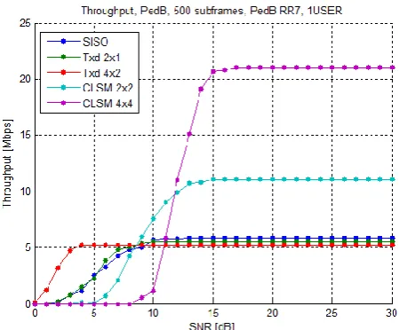
In Data Throughput results for SISO and MIMO modes are presented in the Fig.1 where they are compared to data throughput of SISO configuration. The data throughput of SISO configuration is shown by the blue curve. It can be observed that as the SNR increase the data throughput increase and it reaches its maximum at almost 30 dB. As in BLER results, the high order modulation is behind the high SNR required to achieve the maximum capacity. Beyond this value, the data throughput is constant and it corresponds to the maximum value as calculated in Section III-B. The green curve in Fig1 represents the data throughput of the 2x1 diversity scheme. In diversity scheme in 2x1 diversity scheme the same data is transmitted twice from antenna ports. However, the improvement comes from the fact that to achieve 5 Mbps, the 2x1 diversity scheme requires 1 dB less in SNR with respect to SISO configuration. In other words, the 5 Mbps is achieved by 9 dB SNR in SISO configuration and by only 8 dB in 2x1 diversity scheme. For the 4x2 diversity scheme, red curve in Fig.1, the improvement is even more and the gain in SNR is almost about 5.5 dB. It means that the 5 Mbps data throughput is reached by only 3.5 dB instead of 9 dB in SISO configuration. In this scheme also no multiplexing gain is observed as expected because as in the case of 2x1 diversity scheme only one signal stream is transmitted over the 4 transmit antennas. The multiplexing gain can easily be observed in the case of CLSM scheme, light blue curve for 2x2 and magenta curve shows 4x4 schemes. As in this scheme two and four different signal stream are transmitted simultaneously for 2x2 and 4x4 Spatial multiplexing gain of 2 and 4 is observed and the data throughput is almost doubled in high SNR. In 2x2 CLSM mode we got Data Throughput 12Mbps and 4x4 CLSM scheme Data Throughput of 22 Mbps respectively at high SNR.
B. BLER Results
In Block Error Rate (BLER) results of SISO and MIMO schemes are shown in Figure 2. From the figure it is clear that the worst performances corresponds to the SISO curve (blue curve). The rate of change of the BLER in terms of SNR give us the estimation of the slope of the curve. As discussed in the previous sections, the slope of the BLER curve reflects the diversity order of the system. From the curve it can be observed that the slope is almost equal to one which means that the diversity order is equal to one as expected for the SISO configuration. As the modulation order is 16QAM a relatively high SNR is observed for the good BLER performance. An SNR of 13 dB is required to achieve a 10-2 value of BLER in SISO. The green curve represents the BLER results of the 2x1 diversity scheme. The diversity order of 2x1 system has diversity gain of 2. An SNR gain can also be observed with respect to SISO scheme. In fact, it can be observed that to achieve a 10-1 value of BLER, the 2x1 diversity scheme needs about 1.1 dB less in SNR. In fact the BLER of 10-1 is achieved with 9.1 dB of SNR in SISO configuration however the same value of BLER is achieved with only 8 dB in the 2x1 diversity scheme. So an SNR gain of 1.1 dB is clearly observed for the 2x1 diversity scheme. The BLER results of the 4x2 Diversity scheme are represented by the red curve in Fig.1. In high SNR region the slope of the curve tends to be equal to 8. This value corresponds to the diversity order of a 4x2 system and hence a Diversity Gain of 8 can be observed from the curve. The SNR gain with respect to SISO configuration is more important than the case of 2x1 diversity scheme. In this case, an SNR gain of almost 3 dB at 10-1 value of BLER is obtained. Finally, the BLER results of the CLSM scheme are represented by the light blue curve for 2x2 and magenta curve for 4x4 we can easily observe that the curve is almost parallel to the curve of each other with high SNR. This results is explained by the fact that the CLSM scheme uses the 2x2 and 4x4 antenna ports with two and four different streams. In the CLSM 2x2 curve achieve 10-1 BLER around 12 dB and CLSM 4x4 curve achieve 10-1 BLER around 14 dB. The results shows the fact of multiple streams are sent from different antennas in CLSM 2x2 and 4x4 schemes.
V. CONCLUSION
IJEDR1403010
International Journal of Engineering Development and Research (www.ijedr.org)2952
Figure 1: Throughput vs. SNR of SISO and MIMO modes in LTE-DownlinkFigure 2: BLER vs. SNR of SISO and MIMO modes in LTE-Downlink
REFERENCES
[1]Mehlfuhrer, M. Wrulich, J.C. Ikuno, D. Bosanska and M. Rupp,“Simulating the long term evolution physical layer,” in Proc. Of the 17th European Signal Processing Conference (EUSIPCO 2009), Glasgow Scotland, Aug.2009.
[2]Online , available http://www.nt.tuwien.ac.at/ltesimulator.J. Ikuno, M. Wrulich, and M. Rupp, “System level simulation of lte networks,” in Vehicular Technology Conference (VTC 2010-Spring), 2010 IEEE 71st, may 2010, pp. 1 –5. [3]M. Simko, C. Mehlfuhrer, M. Wrulich, and M. Rupp, “Doubly dispersive channel estimation with scalable complexity,”
in Smart Antennas (WSA) 2010 International ITG Workshop on, feb. 2010, pp. 251 –256.
[4]S. Schwarz, M. Wrulich, and M. Rupp, “Mutual information basedcalculation of the precoding matrix indicator for 3gpp umts/lte,” in Smart Antennas (WSA), 2010 International ITG Workshop on, feb. 2010, pp.52 –58.
[5]S. Schwarz, C. Mehlfuhrer, and M. Rupp, “Calculation of the spatial preprocessing and link adaption feedback for 3gpp umts/lte,” in Wireless Advanced (WiAD), 2010 6th Conference on, june 2010,pp.1–6.
[6]Tse and P. Viswanath, Fundamentals of Wireless Communication. Cambridge University Press, 2008.
[7]S. Sesia, T. Issam, and M. Backer, LTE The UMTS Long Term Evolution From Theory To Practice. John Wiley, 2011. [8]S. Alamouti, “A simple transmit diversity technique for wireless communications,” Selected Areas in Communications,
IEEE Journal on, vol. 16, no. 8, pp. 1451 –1458, oct 1998.
[9] J. G. Andrews, A. Ghosh, and R. Muhamed, Fundamentals of WiMAX: Understanding Broadband Wireless Networking. Prentive HALL, 2007.
[10] ITU-R, “Guidelines for evaluation of radio transmission technologies for IMT-2000”, ITU-R, Tech. Rep. M.1225, 1997.