Power System Stability Studies in a Multi
Machine Infinite Bus System Using UPFC
Malini Palit 1
Assistant Professor, Department of Electrical Engineering, GIMT Azara, Assam, India1
ABSTRACT: POWER systems over the globe are becomingly increasingly complex and the requirements for providing stable, secure, controlled, economic, quality power, especially so in the deregulated environment are becoming vitally important.Flexible AC Transmission Systems (FACTS) devices can be used for power flow control, voltage regulation, enhancement of transient stability and damping of power oscillations.The new generation and most dominant converters needed in FACTS controllers are the STATCOM, the Static Synchronous Series Compensator (SSSC) and the UPFC, which are based on the voltage-source inverters. The UPFC is a typical FACTS controller playing a vital role as a stability aid for small and large transient disturbances in an interconnected power system. The controller is designed by Pq method. Comprehensive computer simulations have been carried out for stability studies of SMIB and multi-machine system with UPFC. The above modeling will be implemented in multi-machine system for transient stability studies.
KEYWORDS:UPFC, Pq method, Custom power source, Steady state stability,Transient stability.
I.INTRODUCTION
Stabilization of a synchronous generator is undoubtedly one of the most important problems in power system control. Power system stabilizers (PSS) and Automatic voltage regulators (AVR) are normally employed to damp out the electromechanical oscillations as well as for the recovery of post-fault bus voltage recovery. However, it is well known that the performances of PSS and AVR are limited since their designs are primarily based on linear control algorithms. In the event of large faults, the non-linearities of the system become very severe, thereby putting limitations on the performances of classical control designs. Fast progression in the field of power electronics has great influence on the power industry One direct outcome of its influence is the concept of Flexible AC Transmission Systems (FACTS), which improves stability to increase usable power transmission capacity to its thermal limit. The family of FACTS devices makes use of insulated gate bipolar transistors (IGBTs) in high power converter configurations that can be controlled to behave as three phase sinusoidal voltage sources, to provide fast control of active and reactive power through a transmission line. A power electronic based system and other static equipment that provides control of one or more AC transmission system parameters is called FACTS controller. The family of FACTS controller includes the Static Var Compensators (SVCs), Static Synchronous Compensators (STATCOMs), Thyristor Controlled Series Compensators (TCSCs), the Static Synchronous Series Compensators (SSSCs), and the Unified Power Flow Controllers (UPFCs). The uses of nonlinear loads are growing rapidly and this kind of loads injects reactive power into the power system. This project presents a new and effective concept of FACTS controllers in order to achieve better reactive as well as real power compensation than other conventional controllers with less complexity
II. RELATED WORK
having two solid-states VSI which are connected with common dc link capacitor. One is static synchronous compensator (STATCOM) and a static synchronous series compensator (SSSC). Hingorani and Gyugyi [12], presented in the basic concept about FACTS devices. This paper discusses all the Power Electronic devices, which can be used to control the basic power system parameters (voltage, current and impedance).The authors describe the basic concepts of the proposed generalized P and Q controller and compare it to the more conventional but related power flow controllers, such as Thyristor-controlled series capacitor and Thyristor control phase angle regulator. Padiyar and Kulkurni[3] in, proposed a cascade PI controller structure for shunt inverter of Unified Power Flow Controller which can be used for STATCOM. R.Mohan Mathur and Rajiv.K.Varma [4] in, presented the applications of FACTS controllers in power transmission line. They also presented about the FACTS devices used for transient stability enhancement. P.Kundur[11] in, presents detailed analysis about stability. The author also clearly explains about the factors affecting transient stability and also about the various methods for enhancing transient stability.
III. OBJECTIVE
The literature review reveals that there exists a need for dynamic modeling of FACTS devices with suitable effective controllers, to damp out electromechanical oscillations as well as to improve the power system stability.
• To develop MATLAB/SIMULINK model of UPFC for MMIB system to improve the power system stability for a open loop system.
• To develop a MATLAB/SIMULINK model of UPFC with proportional integral controller for a closed loop system to improve the power system stability to damp out electromechanical oscillations.
IV. POWER SYSTEM STABILLITY
Introduction
Power system stability is defined as the property of power system that enables it to remain in a state of operating equilibrium under normal operating conditions and to regain an acceptable state of equilibrium after being subjected to a disturbance. It was recognized as a problem as far back as the 1920s at which time the characteristic structure of system consisted of remote power plants feeding load centres over long distances. These early stability problems, as a result of insufficient synchronizing torque, were the first emergence of transient instability. Transient stability is the ability of a power system to remain in synchronism when subjected to large transient disturbances. These disturbances may include faults on transmission elements, loss of load, loss of generation, or loss of system components such as transformers or transmission lines.Although many different forms of power system stability have emerged and become problematic in recent years, transient stability still remains a basic and important consideration in power system design and operation. While it is true that the operation of many power systems are limited by phenomena such as voltage stability or small-signal stability, most systems are prone to transient instability under certain conditions or contingencies and hence the understanding and analysis of transient stability remain fundamental issues. Also, we shall see later in this chapter that transient instability can occur in a very short time-frame (a few seconds) leaving no time for operator intervention to mitigate problems. It is therefore essential to deal with the problem in the design stage or severe operating restrictions may result.
identifying essential factors that contribute to instability and devising methods of improving stable operation is greatly facilitated by classification of stability into appropriate categories. These are based on the following considerations:
1. The physical nature of the resulting instability related to the main system parameter in which instability can be observed.
2. The size of the disturbance considered indicates the most appropriate method of calculation and prediction of stability.
1. The processes and the time span that must be taken into consideration in order to determine stability.
Rotor Angle Stability
Rotor angle stability is concerned with the ability of interconnected synchronous machines of a power system to remain in synchronism under normal operating conditions and after being subjected to a disturbance. It depends on the ability to maintain equal to restore equilibrium between electromagnetic torque and mechanical torque of each synchronous machine in the system. Instability that may result occurs in the form of increasing angular swings of some generators leading to their loss of synchronism with other generators.
The rotor stability problem involves the study of electromechanical oscillations inherent in power systems. The fundamental factor is the manner in which the power outputs of synchronous machines vary as their rotor angle change. The mechanism by which interconnected synchronous machines maintain synchronism with one another is through restoring forces, which act whenever there are forces tending to accelerate or decelerate one or more machines with respect to other machines. Under steady-state conditions, there is equilibrium between the input mechanical torque and the output electrical torque of each machine, and the speed remains constant. If the system is perturbed, this equilibrium is upset, resulting in acceleration or deceleration of the rotors of the machines according to the laws of motion of a rotating body. If one generator temporarily runs faster than another, the angular position of its rotor relative to that of the slower machine will advance. The resulting angular difference transfers part of the load from the slow machine to the fast machine, depending on the power-angle relationship. This tends to reduce the speed difference and hence the angular separation. The power-angle relationship, as discussed above, is highly nonlinear. Beyond a certain limit, an increase in angular separation is accompanied by a decrease in power transfer; this increases the angular separation further and leads to instability. For any given situation, the stability of the system depends on whether or not the deviations in angular positions of the rotors result in sufficient restoring torques.
UNIFIED POWER FLOW CONTROLLER (UPFC)
Definition
A combination of a static synchronous compensator (STATCOM) and a static synchronous series compensator (SSSC) which are coupled via a common dc link, to allow bidirectional flow of real power between the series output terminals of the (SSSC) and the shunt output terminals of the STATCOM, and are controlled to provide concurrent real and reactive series line compensation without an external electric energy source. The UPFC, by means of angular unconstrained series voltage injection, is able to control, concurrently or selectively, the transmission line voltage, impedance, and angle or, alternatively, the real and reactive power flow in the line. The UPFC may also provide independently controllable shunt-reactive compensatation.
Principal of operation:
The UPFC is the most versatile FACTS controller developed so far, with all encompassing capabilities of voltage regulation, series compensation, and phase shifting. It can independently and very rapidly control both real and reactive power flows in a transmission line. It comprises of two VSCs (Voltage Source Converter) coupled through a common dc terminal. VSC 1 is connected in shunt with the line, through a coupling transformer; the other VSC 2 is inserted in series with the transmission line through an interface transformer. The dc voltage for both converters is provided by a common capacitor bank. The series converter is controlled to inject a voltage in series with the line. In this process, the series converter exchanges both real and reactive power with the transmission line. Although the reactive power is internally generated / absorbed by the series converter, the real-power generation / absorption is made feasible by the dc-energy-storage that is the capacitor.
a. Basic UPFC conventional diagram
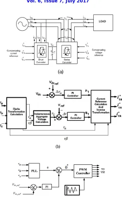
V. UPFC MODELING
(a)
(b)
Fig. 5 (a) Shunt current and voltage compensation (b) Control block of shunt current compensation. (c) Control Block of Series Converter
VI. SIMULATION RESULT
(a)
Fig. 6 Simulation results(a) System subjected to LLG fault with and without UPFC (b) System subjected to LLLG fault with and without UPFC(c)System subjected to LLL fault with and without compensation UPFC
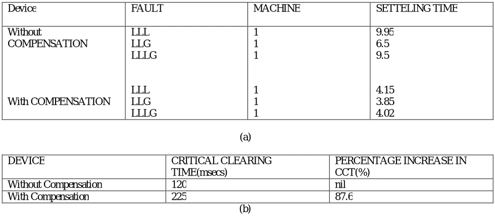
Critical Clearing Time:
The withstanding capability of a device can be said in terms of CCT. It is defined as the maximum time that a device can withstand on application of a fault. A three-phase fault created for period of 0.5 to 0.6seconds and maximum settling time is evaluated.
Device FAULT MACHINE SETTELING TIME
Without
COMPENSATION
With COMPENSATION
LLL LLG LLLG
LLL LLG LLLG
1 1 1
1 1 1
9.95 6.5 9.5
4.15 3.85 4.02
(a)
DEVICE CRITICAL CLEARING
TIME(msecs)
PERCENTAGE INCREASE IN CCT(%)
Without Compensation 120 nil
With Compensation 225 87.6
(b)
VII.CONCLUSION
This research shows that Multimachine system subjected to various power system disturbances and transient stability of power system is analyzed using FACTS device UPFC (Unified power flow controller).
The simulation outputs reveals that UPFC settling time is between 1.5 to 2s. Thus the UPFC has a capability of damping the rotor angle oscillations. Thus, FACTS device UPFC play a vital role in enhancing the transient stability of an MMIB power system. The UPFC shunt converter supplied reactive power into the controller bus for regulated voltage bus. In this study, the results showed that the UPFC can operate and compensate voltage at bus controller rapidly and efficiently
REFERENCES
[1] Kalyan K. Sen, Eric J. Stacey, “UPFC - Unified Power Flow Controller Theory, Modeling, and Applications”, IEEE transactions on Power Delivery, Vol.13,No.4, octobor 1998.
[2] P.Kundur, “Power system stability and control”.Tata Mcgraw hill.
[3] Mathur.R.M., Varma.R.K, “Thyristor based FACTS controllers for electrical transmission systems”, IEEE Press.
[4] Kalyan K. Sen, Stacey, Eric J., “UPFC – unified power flow controller: theory, modeling and applications”, IEEE Transactions on Power Delivery, Vol. 13, No. 4, 1998
[5] Ramnarayan Patel, T. S. Bhatti and D. P. Kothari,” MATLAB/Simulink-based transient stability analysis of a multimachine power system.” Yassin M. Y. Hasan and Lina J. Karam, “Morphological Text Extraction from Images”, IEEE Transactions On Image Processing,
vol. 9, No. 11, 2000.
[6] I. J. Nagrath and D. P. Kothari , Power system Engineering (Tata McGraw-Hill, New Delhi, 1994).
[7] Dash P.K ., Mishra S. and Liew A.C., “Design of a Fuzzy PI Controller for Power System Application”, International Journal of Intelligent and Fuzzy System, Vol.1, pp. 19-24, 1995.
[8] V. Khadkikar1, A. Chandra1, “Application of UPQC to Protect a Sensitive Load on a Polluted Distribution Network”, 2006 IEEE.
[9] Panumat Sanpoung, Paisan Boonchiam and Boonyang Plangklang, “Analysis and control of UPFC for voltage compensation using ATP/EMTP”, As. J. Energy Env. 2009, 10(04), 241-249.