An Improved Algorithm for Deducing Complex Permittivity of Thin
Dielectric Samples with the Transmission/Reflection Method
Minghui Ding1, Yanqing Liu2, Xinru Lu1, Yifeng Li3, and Weizhong Tang1, *
Abstract—Transmission/reflection method is widely used in microwave engineering for determining dielectric properties of materials, and significant uncertainty will arise in the results if the thickness of the samples is small. In this paper, we propose an improved algorithm for deducing complex permittivity of thin dielectric samples with the transmission/reflection method. With the proposed algorithm, the real and imaginary parts of the complex permittivity will be treated separately, and two independent weighting factors, βre and βim, will be used to minimize the uncertainty in both parts of the complex
permittivity. Numerical calculations as well as experimental measurements on undoped and boron-doped diamond films were conducted within the frequency range of 18.5–26.5 GHz to demonstrate the effectiveness of the algorithm. It is verified that among the various iterative algorithms which could be used to derive complex permittivity, the proposed algorithm is the most advantageous in reducing uncertainties when thin dielectric samples are dealt with.
1. INTRODUCTION
Determination of a material’s dielectric property is a prerequisite for application of the material in the field of microwave engineering. For this reason, many measuring techniques have been developed which could generally be divided into two groups, i.e., resonant and non-resonant methods [1]. Among the various techniques, the transmission/reflection (T/R) method is widely used because of its simplicity in equipment and capability in wideband measurements.
In the T/R measurement, a sample is inserted into either a waveguide, a coaxial line or a stripling, and complex permittivity of the sample will be deduced from scattering parameters (S -parameters) measured at the two ends of the measurement fixture. This method was first proposed by Nicolson and Ross [2], and Weir [3], so was given the name NRW algorithm. During the last decades, progressive improvements have been made on the T/R method [4–12]. Baker-Jarvis et al. [9] proposed an iterative approach to eliminate the ill-behavior of the original NRW algorithm. They showed that by incorporating a weighting factor β into the algorithm, the uncertainty of the complex permittivity derived from the algorithm could be effectively reduced. Later on, Kato et al. [10] proposed an alternative approach in selecting the weighting factor, in order to further minimize the uncertainty in determining the complex permittivity. However, by referring to the results shown in [10], it can be seen that the uncertainty of the imaginary part of the complex permittivity determined in such a way may not necessarily be decreased, though uncertainty in the real part of the result may be reduced.
Generally speaking, even with an iterative algorithm, significant uncertainty will arise in deriving the complex permittivity, if the thickness of the sample is small. In this paper, we propose a further improvement on the iterative algorithms developed by Baker-Jarvis et al. [9] and Kato et al. [10]. In
Received 18 June 2019, Accepted 13 August 2019, Scheduled 20 August 2019
* Corresponding author: Weizhong Tang ([email protected]).
our approach, the real and imaginary parts of the complex permittivity will be treated separately, and two weighting factors, βre and βim, will be employed in the iterative calculation, so as to decrease the uncertainty in both the real and imaginary parts of the complex permittivity. Uncertainty analysis will be conducted by numerical calculations, showing that with the proposed algorithm both the real and imaginary parts of the complex permittivity of thin samples may be more accurately determined than those derived using alternative algorithms. Experimental measurements are carried out on thin undoped and boron-doped diamond films to prove the effectiveness of the improved algorithm in measuring complex permittivity of thin dielectric samples.
2. THEORETICAL BACKGROUND
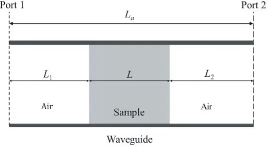
Figure 1 shows a schematic of the T/R method in measuring dielectric properties of a sample within a rectangle waveguide. The situations with a coaxial line [9] or a stripline [13] as measurement fixtures may be similarly treated. In the figure, L is the thickness of the sample with a relative complex permittivity εr and relative complex permeability μr; La is the length of the waveguide fixture; L1
and L2 are the distances between the sample surfaces and the relevant reference planes (port 1 and 2),
respectively. S-parameters (Sij, i, j = 1,2) are measured at ports 1 and 2 by using a vector network analyzer connected to the waveguide fixture.
Figure 1. Schematic of the T/R method with a rectangular waveguide as the measurement fixture.
One of the most widely used equations derived by Baker-Jarvis et al. [9] for determining the complex permittivity εr of the sample is of the form:
S12S21−S11S22= z 2−Γ2
1−Γ2z2 exp [2γ0(La−L)] (1)
where Γ = (γ0−γ)/(γ0+γ) and z = exp(−γL) are the reflection coefficient and propagation factor,
and γ0 and γ are the propagation constants of microwave in air and in the sample, respectively. The
latter two parameters are related to the complex permittivity εr and complex permeability μr of the sample by relations shown below:
γ0=j
(ω/c)2−(2π/λc)2, γ=j
(ω/c)2εrμr−(2π/λc)2 (2)
where c is the speed of light in vacuum and ω the microwave angular frequency, and λc the cutoff wavelength of the waveguide. In the following, we deal only with the situation in which the sample is made of a nonmagnetic material, thus we haveμr= 1
In order to improve accuracy of the calculation, another equation containing a weighting factorβ may be used [9]:
1
2{exp [γ0(La−L)] (S12+S21) +β{S11+ exp [2γ0(La−L)]S22}}=
z1−Γ2+βΓ1−z2
Application of this equation requires that the condition L1 = 0 is satisfied.
Both Eqs. (1) and (3) are complex functions from which complex permittivity of the sample is to be deduced. We see from these equations thatS-parameters,La,L, and their uncertainties would affect accuracy of the derived complex permittivity through their uncertainty transfer coefficients (UTCs, denoted as partial derivatives in [9]). Air gaps between the sample and measurement fixture walls may also contribute to the uncertainties of the result. But the latter problem has been thoroughly treated in the literature [14], so in this paper this effect will no longer be discussed.
After rewriting Eq. (3) in the form of F(εr, L, La, S, β) = 0, UTCs between all variables may be derived. For example, the UTC of the real part of the complex permittivity, εr, to one of the
S-parameters, S21, may be written as:
∂ε r
∂|S21|
= Re ⎧ ⎪ ⎨ ⎪ ⎩ 1
2exp [γ0(La−L)]e jθ21
∂F /∂εr
⎫ ⎪ ⎬ ⎪ ⎭, ∂ε r ∂θ21
=j|S21| ∂ε
r
∂|S21|
(4)
where |S21| and θ21 are the amplitude and argument of scattering parameter S21. All other UTCs of
every parameter could be derived similarly. After all UTCs are obtained, uncertainties in the real and imaginary parts of the complex permittivity may be expressed:
Δεr = i,j
∂εr
∂|Sij|Δ|Sij| 2
+
∂εr
∂θijΔθij 2
+
∂εr
∂LΔL
2
+
∂εr
∂LaΔLa 2
(5)
Δεr = i,j ∂ε r
∂|Sij|Δ|Sij| 2
+
∂ε r
∂θijΔθij 2
+
∂ε r
∂LΔL
2
+
∂ε r
∂LaΔLa 2
(6)
wherei={1,2}, j ={1,2}, andεr is the imaginary part of the complex permittivity.
It is clear from Eq. (4) that any change in the weighting factorβ would change relevant UTCs which would affect overall uncertainties of the ultimate results. Therefore, the weighting factor β should be optimally determined.
In [9], it is suggested thatβ is chosen as the ratio between the uncertainties of twoS-parameters, Δ|S21|/Δ|S11|. Choice of β in this way would decrease the overall uncertainty of the complex
permittivity by weighting heavily on the S-parameter with less uncertainty. However, Kato et al. [10] pointed out that a so-determinedβ may not be optimal. They suggested that β is chosen to minimize (Δεr)2+ (Δεr)2 the sum of the squares of uncertainties in both the real and imaginary parts of the complex permittivity. However, as we will show in the next section, choice of β in this way may not necessarily mean that the uncertainties in both the real and imaginary parts of the complex permittivity are decreased.
To circumvent the problem, in this paper we propose a further improvement on the choice ofβ. In our approach, two distinct weighting factors,βre and βim, will be used separately to optimize the real and imaginary parts of the complex permittivity. In other words, βre will be chosen to minimize Δεr, so doesβim to minimize Δεr. Similar to the situation in [10], the uncertainties Δεr and Δεr could be derived as follows:
Δεr2 = c1+c2βre+c3β
2
re
c4+c5βre+c6βre2
(7)
Δεr2 = c7+c8βim+c9β
2
im
c10+c11βim+c12βim2
(8)
where c1, c12 are coefficients dependent on L, La, εr, S-parameters, and their uncertainties, but
independent of the weighting factors. Thus, two distinct weighting factors, βre and βim, may be selected to minimize Δεr and Δεr separately, and then these two weighting factors are used to derive two complex permittivities, εr1 and εr2. Finally, a new complex permittivity, εr =εr1−jεr2, will be
3. NUMERICAL CALCULATIONS
Numerical calculation is made for a thin dielectric sample with a complex permittivity ofεr= 2(1−j0.1). Dimensions of the measurement are assumed as follows: L = 0.6 mm, La = 4.5 mm, and L1 = 0. The
frequency range is assumed in the K-band (18–26.5 GHz). Within this frequency range, the thickness of the sample is comparatively small (less than 10% of the microwave wavelength in the sample), so significant uncertainty will arise.
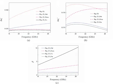
In the calculation, uncertainties inS-parameters are derived for an Agilent N5244a vector network analyzer [15], and uncertainties in dimensions are assumed as ΔL = 0.01 mm and ΔLa = 0.02 mm, respectively. Fig. 2 shows uncertainties calculated for the real and imaginary parts of the complex permittivity together with weighting factors obtained by the different algorithms as a function of frequency. In the following, these three algorithms based on using Eq. (3) will be designated as the Baker-Jarvis method (βBJ), Kato method (βBJ), and proposed method, respectively. For the sake of comparison, the algorithm by using Eq. (1) has also been included.
(a) (b)
(c)
Figure 2. Uncertainties in (a) the real and (b) imaginary part of the complex permittivity and (c) the weighting factors vs frequency.
The latter result is consistent with that obtained in the literature [10].
Figure 2(b) shows the uncertainty calculated for the imaginary part of the complex permittivity. It is striking to see that the uncertainty obtained with the Kato method is higher than that with the Baker-Jarvis method, consistent again with the result of the literature [10]. And among all the algorithms used in the calculation, the proposed method results in the lowest uncertainty. This is because the method separates the optimization process for the real and imaginary parts of the calculation, thus avoiding their interference and improving accuracy of the results. It can also be seen from Fig. 2(b) that the uncertainty in the imaginary part of the complex permittivity obtained with the Kato method is either very close to or even higher than that derived by using Eq. (1) at high frequencies (> 25 GHz). This proves that if the weighting factor in Eq. (3) is not properly selected, accuracy of the results will not necessarily be improved, as compared with that obtainable with the conventional algorithm (Eq. (1)).
Figure 2(c) compares weighting factors obtained with the three different algorithms. It could be seen that, firstly, the two weighting factors obtained with the proposed method are quite different, while those obtained with the Kato and Baker-Jarvis methods are in between these two weighting factors. Secondly, the weighting factor obtained with the Baker-Jarvis method is very close to βim, and this is also reflected in the fact that the uncertainties in the imaginary part of the permittivity obtained with both the Baker-Jarvis and the proposed method are close to each other. Since with the proposed method, two weighting factors have been used to calculate the real and imaginary parts of the complex permittivity, respectively, the uncertainties in both parts of the results may be simultaneously the lowest.
4. A SIMPLE EXPLANATION OF THE PROPOSED ALGORITHM
Above, we have proposed that in using the iterative approach in solving Eq. (3), two weighting factors,
βreandβim, may be used separately to deduce the real and imaginary parts of the complex permittivity. In the following, rationality of the proposed algorithm will be briefly discussed.
We firstly rewrite Eq. (3) in its general form as
Fεr, εr, L, La, S, β= 0 (9)
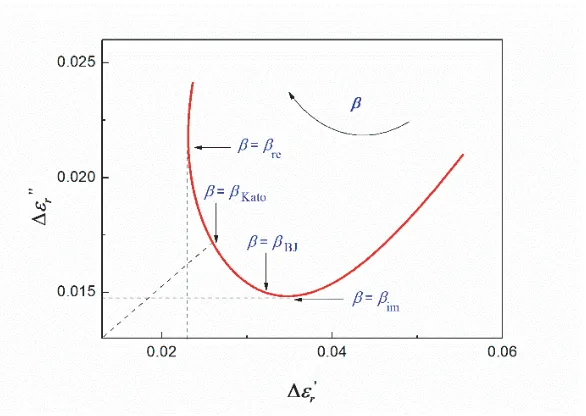
where the weighting factorβhas been incorporated to improve the accuracy of the complex permittivity caused by measurement uncertainties in dimensions and S-parameters. Thus, the uncertainties of the real and imaginary parts of complex permittivity will all be β dependent (Eqs. (7) and (8)). Fig. 3 shows schematically the interrelationship between the uncertainties in the real and imaginary parts of
the permittivity and weighting factorβ. The result has been calculated using the data taken from Fig. 2 for a frequency of 25 GHz.
Just as in Kato’s algorithm [10] in deducing the permittivity, we may impose the following
restriction
Δεr2+Δεr2= min (10) In such a procedure, a specific weighting factor βkato will be obtained. It can be seen from Fig. 3 that
Eq. (3) corresponds to the nearest distance of the curve to the origin. It could be noted from Fig. 3 that at this time both Δεr and Δεr are not the minimum. Instead, another form of restriction may be
imposed, such as
Δεr2= min (11)
This time, the permittivity will be deduced aiming to minimize the uncertainty in the real part of the permittivity (with a new weighting factorβre), as indicated also in Fig. 3. It should be emphasized that the thus obtained real part of the permittivity (together with its uncertainty) will be valid irrespective of whether its imaginary counterpart will be explicitly used or not. This is because the thus deduced real part of the permittivity (and its uncertainty) has been calculated using the basic equation (Eq. (9)).
Likewise, a similar restriction may be imposed in solving Eq. (9):
Δεr2 = min (12)
aiming to minimize the uncertainty in the imaginary part of the permittivity. The result with the weighting factor βim obtained is also indicated in Fig. 3. The thus obtained imaginary part of the permittivity (with its uncertainty) will remain valid irrespective of whether its real counterpart will be explicitly stated or not, since it has been calculated from the basic equation (Eq. (9)).
It could be imagined that in using the Baker-Jarvis’ algorithm [9] the result derived for the complex permittivity (together with a weighting factorβBJ) will also be located somewhere along the curve shown in Fig. 3. However, according to the former discussions the algorithm has been unable to minimize uncertainties in both parts of the permittivity either individually or collectively.
Thus, it can be seen that among all the algorithms, the proposed algorithm is the most effective in minimizing uncertainties in deducing complex permittivity of thin samples.
5. DETERMINATIONS OF PERMITTIVITY OF DIAMOND FILMS
Above we have shown that whereas various iterative algorithms may be used to deduce complex permittivity for thin dielectric samples, an improved algorithm may be employed to improve the accuracy of the results. To validate this conclusion, measurements are made on an undoped and a boron-doped diamond film. These two samples have been selected since firstly the thickness of the two samples is small, and secondly while the undoped diamond film may be used as a standard sample, the boron-doped diamond film may be used as a representative high dielectric loss sample.
In the measurements, an Agilent N5244a vector network analyzer is used. A Thru-Reflect-Line calibration procedure [10] is carried out before the measurements. Samples are inserted into aK-band waveguide fixture with a length ofLa= 4.5 mm. From measuredS-parameters, complex permittivity of the samples is derived using the various algorithms mentioned above. Dimension uncertainties in both the fixture and the samples are ΔLa= 0.02 mm, ΔL= 0.01 mm, respectively.
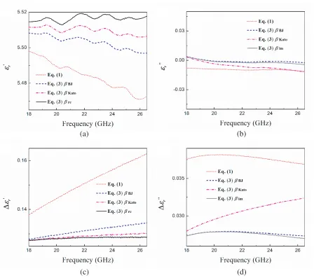
Figure 4 shows the results derived with the various algorithms for the undoped diamond film. The thickness of the sample is only 0.37 mm. It is shown by using resonant cavity methods that an undoped diamond film will have a relative permittivity between 5.5 and 5.7, and its dielectric loss tangent is less than 10−4 [16–19]. In Figs. 4(a), (c), we see that the uncertainty in the real part of the permittivity derived by using Eq. (1) remains the largest, while that obtained with the proposed method is the lowest. Also, from Fig. 4(a) we see that the real part of the permittivity derived by the proposed method is in the range of 5.51±0.15 which not only has the smallest uncertainty, but also is frequency independent. This is consistent with the results of the literature [18]. In contrary, all results derived with the other methods somewhat show frequency dependency.
(a) (b)
(c) (d)
Figure 4. (a) The real and (b) imaginary part of the complex permittivity and (c), (d) their uncertainties measured for the undoped diamond film.
proposed algorithm is better than all the others. On the other hand, from Fig. 4(c) we notice that the values of the imaginary part of the complex permittivity derived by all the four algorithms are physically meaningless (far from the accurate valueεr ≈0.0003 measured by using a split-cylinder resonator [19]). This discrepancy is because the non-resonant T/R method is limited in its accuracy in measuring the imaginary part of the complex permittivity when being used to characterize low-loss materials [20].
Figure 5 shows the results of the complex permittivity and corresponding uncertainties for the boron doped diamond film. The thickness of this sample is 0.46 mm, and its boron concentration has been determined by FT-IR as 6.0×1018cm−3 [21]. From Figs. 5(a), (b), we see that for this high-loss
(a) (b)
(c) (d)
Figure 5. (a) The real and (b) imaginary part of the complex permittivity and (c), (d) their uncertainties measured for the boron doped diamond film.
6. CONCLUSIONS
In this paper, an improved iterative algorithm for deducing complex permittivity of thin dielectric samples is proposed. The improvement has been made on the algorithms previously developed by Baker-Jarvis et al. and Kato et al. It is shown that by using two distinct weighting factors separately in determining the real and imaginary part of the complex permittivity, more accurate results may be obtained. Numerical calculations are carried out, and experimental measurements are made on two thin diamond film samples, proving that the proposed algorithm is effective in reducing measurement uncertainty in measuring dielectric properties of thin samples with the T/R method.
REFERENCES
1. Chen, L. F., C. K. Ong, C. P. Neo, V. V. Varadan, and V. K. Varadan, Microwave Electronics: Measurement and Materials Characterization, John Wiley & Sons, Ltd, England, 2004.
2. Nicolson, A. M. and G. F. Ross, “Measurement of the intrinsic properties of materials by time-domain techniques,” IEEE Transactions on Instrumentation and Measurement, Vol. 19, 377–382, 1970.
4. Kim, S. and J. R. Guerrieri, “Low-loss complex permittivity and permeability determination in transmission/reflection measurements with time-domain smoothing,”Progress In Electromagnetics Research M, Vol. 44, 69–79, 2015.
5. Hasar, U. C., J. J. Barroso, C. Sabah, and Y. Kaya, “Resolving phase ambiguity in the inverse problem of reflection-only measurement methods,”Progress In Electromagnetics Research, Vol. 129, 405–420, 2012.
6. Kim, S. and J. Baker-Jarvis, “An approximate approach to determining the permittivity and permeability near λ/2 resonances in transmission/reflection measurements,” Progress In Electromagnetics Research B, Vol. 58, 95–109, 2014.
7. Hasar, U. C., “Self-calibrating transmission-reflection technique for constitutive parameters retrieval of materials,” IEEE Transactions on Microwave Theory and Techniques, Vol. 66, 1081– 1089, 2018.
8. Hasar, U. C., “Thickness-invariant complex permittivity retrieval from calibration-independent measurements,” IEEE Microwave and Wireless Components Letters, Vol. 27, 201–203, 2017. 9. Baker-Jarvis, J., E. J. Vanzura, and W. A. Kissick, “Improved technique for determining complex
permittivity with the transmission/reflection method,” IEEE Transactions on Microwave Theory and Techniques, Vol. 38, 1096–1103, 1990.
10. Kato, Y., M. Horibe, M. Ameya, S. Kurokawa, and Y. Shimada, “New uncertainty analysis for permittivity measurements using the transmission/reflection method,” IEEE Transactions on Instrumentation and Measurement, Vol. 64, 1748–1753, 2015.
11. Hasar, U. C., Y. Kaya, J. J. Barroso, and M. Ertugrul, “Determination of reference-plane invariant, thickness-independent, and broadband constitutive parameters of thin materials,”IEEE Transactions on Microwave Theory and Techniques, Vol. 63, 2313–2321, 2015.
12. Kato, Y. and M. Horibe, “Improvement of transmission/reflection method for permittivity measurement using long fixtures with time-domain,” IEEE Transactions on Instrumentation and Measurement, Vol. 66, 1201–1207, 2017.
13. Barry, W., “A broad-band, automated, stripline technique for the simultaneous measurement,”
IEEE Transactions on Microwave Theory and Techniques, Vol. 34, 80–84, 1986.
14. Baker-Jarvis, J., “Transmission/reflection and short-circuit line permittivity measurement,” NIST Project, National Institute of Standards and Technology, Colorado, 1990.
15. Vector network analyzer uncertainty calculator, Keysight Software, version: 5.0.6.0, Jul. 2017. 16. Yamada, H., A. Meier, F. Mazzocchi, S. Schreck, and T. Scherer, “Dielectric properties of single
crystalline diamond wafers with large area at microwave wavelengths,” Diamond and Related Materials, Vol. 58, 1–4, 2015.
17. Thumm, M., “MPACVD-diamond windows for high-power and long-pulse millimeter wave transmission,” Diamond and Related Materials, Vol. 10, 1692–1699, 2001.
18. Heidinger, R., G. Dammertz, A. Meier, and M. K. Thumm, “CVD diamond windows studied with low- and high-power millimeter waves,” IEEE Transactions on Plasma Science, Vol. 30, 800–807, 2002.
19. Liu, Y. Q., M. H. Ding, J. J. Su, H. Ren, X. R. Lu, and W. Z. Tang, “An investigation on dielectric properties of diamond films in the range of K and Ka band,” Diamond and Related Materials, Vol. 73, 114–120, 2017.
20. Hasar, U. C., “Self-calibrating transmission-reflection technique for constitutive parameters retrieval of materials,” IEEE Transactions on Microwave Theory and Techniques, Vol. 66, 1081– 1089, 2018.