An Angular Stabilized Frequency Selective Surface by Using
Capacitance Layers Structure
Meng Sun1, Shaowei Bie1, *, Ling Miao1, Qian Chen2, and Jianjun Jiang1
Abstract—A band-pass frequency selective surface (FSS) structure using capacitance layers is proposed to improve the performance of angular stability. It consists of band-pass FSSs, supporting dielectrics, and capacitance layers out of band-pass FSS. The supporting dielectrics and capacitance layers work as a transmission line and capacitance impedance matcher. Through the impedance matcher, the bandwidth is stabilized, and insertion loss at passband is reduced from −0.76 dB to −0.39 dB for incident angles up to 60◦. The equivalent circuit of the proposed structure is presented, and the Smith chart is given to explain the mechanism of the capacitance layers. Finally, a prototype is manufactured and measured. A relatively good agreement is obtained between simulations and measurements. Therefore, the proposed structure can be an effective solution to improve the angular stability performance of band-pass FSS design.
1. INTRODUCTION
Typical frequency selective surfaces are one- or two-dimensional periodic structures which consist of metal patterns and dielectric substrates. FSS is essentially a kind of spatial filter, which does not absorb any energy itself. In recent years, FSS has been drawing a lot of attention for working as a spatial filter with a band-pass characteristics [1–10]. They are widely used in the electromagnetic field as filters, absorbers, radomes, and antenna reflectors. However, the properties of resonant frequency, bandwidth, and insertion loss are different from normal incidence for a band-pass FSS when the incident angle changes. Thus, the problem of angular stability becomes a major concern for actual applications. The common techniques to improve angular stability can be classified into two categories. In the first category, miniaturized elements frequency surface (MEFSS) is utilized to improve the oblique incident performance through reducing the unit size. Parker et al. have proposed a method in which the metal lines were twisted and turned to increase the electrical length and reduce the unit size, and went a step further, interwoven elements were proposed, in which the coupling effect between neighbor elements was enhanced to make the unit size smaller [1, 2, 9, 10]. Then another method has been proposed by Liu et al. that metal patterns can be replaced by capacitors (C) or inductors (L). The unit size was greatly reduced, and the resonant frequency mainly depended on the value of C and L [3]. In recent years, Sarabandi and Behdad have proposed a new miniaturized structure [4–7, 11], which used strong coupling between the capacitive layer and inductive layer to realize miniaturized unit. MEFSS can make the imaginary part of FSS’s impedance stable, so the performance of resonant frequency was improved. In order to improve the performance of bandwidth, that is, stabilizing the real part of impedance, the second category outer dielectric bonding technique is required. Loading dielectrics with relative permittivity of 1 + cosθ (θis the maximum of incident angle) at both sides of FSS is an effective way to get a constant bandwidth and flat top [7, 8, 12] according to Munk.
Received 17 May 2019, Accepted 19 September 2019, Scheduled 8 October 2019 * Corresponding author: Shaowei Bie ([email protected]).
1 School of Optical and Electronic Information, Huazhong University of Science and Technology, Wuhan 430074, China. 2 38th
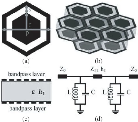
combination of inductive grid FSS and capacitive patches FSS. Normally, slot FSS has a more stable performance in resonant frequency since the FSSs combination is sensitive to the thickness of dielectrics between FSSs. In addition, because of the shape and triangle configuration, the hexagon loop slot has smaller element size than other simple patterns like square loop slot and ring slot. Therefore, the second order band-pass structure is designed with a unit cell of hexagon loop slot and configuration of are gular triangle. The structure is shown in Figure 1, and pertinent geometric parameters of the structure are defined as follows: h1 = 7 mm,p= 10 mm,r= 3.8 mm,s= 1.5 mm. It is generally known
that metallic lines can be equivalent to an inductor (L), and slots can be equivalent to a capacitor (C) under the incident electromagnetic wave, so the second order band-pass structure can be equivalent to a L-C parallel circuit which is shown in Figure 1, and the resonance frequency is determined by L and C.
(a) (b)
(c) (d)
Figure 1. Configuration of the band-pass structure. (a) Top view of the unit cell. (b) 3-D view. (c) Side view. (d) Equivalent circuit.
Table 1. Performance parameters of band-pass structure.
fL (−3 dB) fH (−3 dB) Center Frequency Bandwidth
0◦ (TE) 7.4 GHz 13 GHz 10.2 GHz 5.6 GHz
60◦ (TE) 8.7 GHz 12.5 GHz 10.6 GHz 4.1 GHz
0◦ (TM) 7.4 GHz 12.9 GHz 10.15 GHz 5.5 GHz
(a) (b)
Figure 2. Simulated transmission coefficient of the band-pass structure.
Simulations by HFSS are completed. The transmission coefficient of the structure is shown in Figure 2, and its corresponding parameters is shown in Table 1. The insertion loss at normal incidence is higher than oblique incidence, especially in TE mode. The resonant frequency moves to higher values, and bandwidth is reduced in TE mode and increased in TM mode.
2.2. Band-Pass Structure with Capacitance Layers
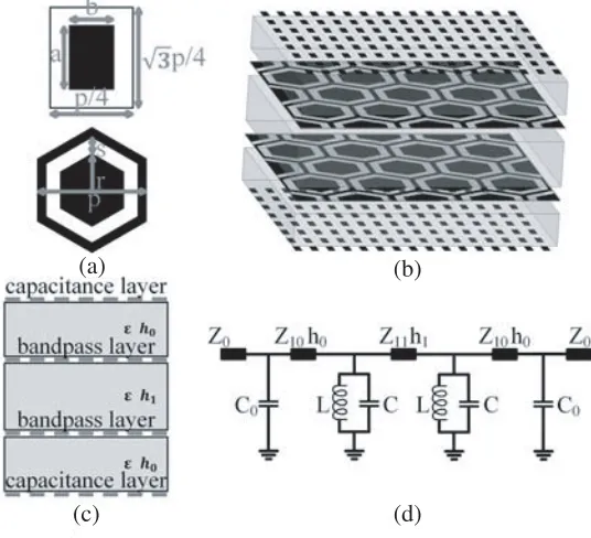
In order to improve the angular stability, capacitance layer structures are added on both sides of the second order band-pass structure. The four-tier structure of angular stabilized band-pass filter is shown in Figure 3 in which black areas represent metallic lines. The geometric parameters of the FSS are defined as follows: h0 = 5 mm, h1 = 7 mm, p = 10 mm, r = 3.8 mm, s = 1.5 mm, a = 2.2 mm,
b = 1 mm. Dielectric support between capacitance layer and band-pass layer are honeycomb with
(a) (b)
(c) (d)
(a) (b)
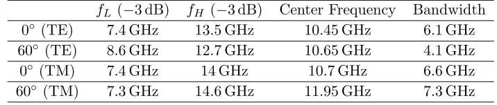
Figure 4. Simulated transmission coefficient of the band-pass structure with capacitance layers.
Table 2. Performance parameters of band-pass structure with T-C matching network.
fL (−3 dB) fH (−3 dB) Center Frequency Bandwidth
0◦ (TE) 7.4 GHz 13.5 GHz 10.45 GHz 6.1 GHz
60◦ (TE) 8.6 GHz 12.7 GHz 10.65 GHz 4.1 GHz
0◦ (TM) 7.4 GHz 14 GHz 10.7 GHz 6.6 GHz
60◦ (TM) 7.3 GHz 14.6 GHz 11.95 GHz 7.3 GHz
2.3. Mechanism Analysis
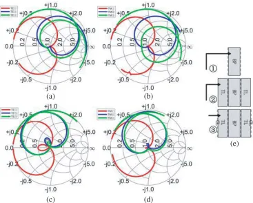
To explain the mechanism, Smith chart of reflection coefficients of the structure is given in Figure 5. Line 1 is for band-pass (BP) layers only. According to the transmission line theory, the free space impedance changes fromZ0(120π) for both TE and TM modes toZ0/cosθfor TE mode andZ0×cosθ
for TM mode when the incident angle changes from 0 to θ, and the thickness of the dielectric support also changes fromh1toh1×cosθ. Therefore, compared to the normal incidence, the resonant frequency
(a) (b)
(c) (d)
(e)
Figure 5. Smith chart of the stabilization process from 2–16 GHz. (a) 0◦, TE mode. (b) 0◦, TM mode. (c) 60◦, TE mode. (d) 60◦, TM mode. (e) Structure diagram.
h0 is designed to satisfy the condition for 2βh0 ×cosθ < π/2 to reduce the insertion loss at 60◦, so
h0 is slightly smaller than λ/4 where λ refers to the wave length of the resonant frequency. Finally,
after adding the capacitance layers (CL), points on line 2 rotate along the constant conductivity circle to line 3. For the capacitance layers and transmission line, the effects on normal incidence and oblique incidence are different. For normal incidence, both TE and TM modes have a lower reflection coefficient on the low frequency side and higher reflection coefficient on the high frequency side which means that the resonant frequency is shifted to a higher value. For oblique incidence, for example 60◦, both TE and TM modes have a lower reflection coefficient on the low frequency side, but the reflection coefficient on the high frequency side changes little since the curve is near the real axis on the high frequency side. Therefore, bandwidth is reduced. Thus, through a reasonable design, performance of resonant frequency and bandwidth can be improved. In addition, as shown in Figure 3(c), the maximum insertion loss points at passband of line 2 are in the fourth quadrant since h0 is slightly smaller than λ/4, thus
the insertion loss is reduced by the effect of capacitance layers.
3. FABRICATION AND MEASUREMENT
Figure 6. Test environment of transmission coefficient.
(a) (b)
Figure 7. Measured transmission coefficients of the angular stabilized band-pass FSS for different polarizations and incident angles. (a) TE mode. (b) TM mode.
are shown in Figure 7. The measured results of resonant frequency and bandwidth basically tally with the simulated results.
4. CONCLUSION
In this letter, an angular stabilized second order band-pass FSS using a capacitance layers structure is proposed. An AT-C matching network is introduced to improve its angular stability as the incident angle changes from normal to 60◦. Moreover, the mechanism is analyzed by equivalent circuit and Smith chart. Finally, the structure is fabricated and measured. The results show that the performance of angular stability is improved for resonant frequency, bandwidth, and insertion loss. The experimental results agree with the simulated ones.
ACKNOWLEDGMENT
REFERENCES
1. Zhao, P., Z. Zong, W. Wu, B. Li, and D. Fang, “Miniaturized-element bandpass FSS by loading capacitive structures,”IEEE Transactions on Antennas and Propagation, Vol. 67, No. 5, 3539–3544, May 2019.
2. Li, D., Z. Shen, and E. P. Li, “Spurious-free dual-band bandpass frequency-selective surfaces with large band ratio,” IEEE Transactions on Antennas and Propagation, Vol. 67, No. 2, 1065–1072, Feb. 2019.
3. Liu, H. L., K. L. Ford, and R. J. Langley, “Design methodology for a miniaturized frequency selective surface using lumped reactive components,” IEEE Transactions on Antennas and Propagation, Vol. 57, No. 9, 2732–2738, Sep. 2009.
4. Sarabandi, K. and N. Behdad, “A frequency selective surface with miniaturized elements,” IEEE Transactions on Antennas and Propagation, Vol. 55, No. 5, 1239–1245, May 2007.
5. Li, T. W., D. Li, and E. P. Li, “A novel FSS structure with high selectivity and excellent angular stability for 5G communication radome,”2017 10th Global Symposium on Millimeter-Waves, 50–52, Hong Kong, 2017.
6. Wang, H., L. Zheng, M. Yan, J. Wang, S. Qu, and R. Luo, “Design and analysis of miniaturized low profile and second-order multi-band polarization selective surface for multipath communication application,”IEEE Access, Vol. 7, 13455–13467, 2019.
7. Liu, X., Q. Wang, W. Zhang, M. Jin, and M. Bai, “On the improvement of angular stability of the 2nd-order miniaturized FSS structure,”IEEE Antennas and Wireless Propagation Letters, Vol. 15, 826–829, 2016.
8. Liang, E. and T. K. Wu, “Novel wideband frequency selective surface filters with fractal elements,”
Microwave Journal, Vol. 60, 102–110, Nov. 2017.
9. Parker, E. A., A. N. A. El Sheikh, C. De, and A. C. Lima, “Convoluted frequency-selective array elements derived from linear and crossed dipoles,” IEE Proc. H, Vol. 140, No. 5, 378–380, 1993. 10. Yan, M., S. Qu, H. Ma, et al., “Convoluted element frequency selective surface with miniaturization
and wideband response,” 2016 IEEE MTT-S International Microwave Workshop Series on
Advanced Materials and Processes for RF and THz Applications (IMWS-AMP), 1–3, Chengdu,
2016.
11. Omar, A. A. and Z. Shen, “Thin bandstop frequency-selective structures based on loop resonator,”