A Novel Filtering Antenna Using Dual-Mode Resonator
Zhi-Hong Yao and Dong Chen*
Abstract—In this paper, a filtering antenna using a dual-mode resonator is presented. The rectangular patch performs not only as a radiator, but also as the last resonator of the bandpass filter. The dual-mode resonator works together with the patch antenna to form a third order bandpass filter with Chebyshev responses. The filtering antenna exhibits good performance, such as skirt selectivity, flat gain within the passband, and high out-of-band suppression.
1. INTRODUCTION
Both antennas and filters are key components in a passive circuit. Usually, filters are designed just behind the antenna for selecting signals within the operating band and rejecting the spurious. With the development of wireless communication, a growing need for high-performance and portable terminal equipment prompts the miniaturization and integration of antennas and filters.
Several efforts have been made to integrate filters with antennas [1–9]. The direct method is to design the antenna and filter separately and then integrate together by adding a matching circuit. However, such design methods dramatically enlarge the circuit size [1–3]. In [4–6], a filtering antenna is built by replacing the filter with a new structure embedded in the antenna. Nevertheless, this design method includes so many structure parameters and so much optimization process, which are complicated and time consuming. Recently, filtering antennas, designed following the synthesis process of bandpass filter (BPF), have been presented in [7–9]. In those designs, the last resonator and the load impedance of BPF were substituted by the patch antenna.
In this letter, a compact 3rd-order filtering antenna composed of a dual-mode resonator and a rectangular patch antenna is presented. The patch antenna and dual-mode resonator work together as a 3rd-order BPF with Chebyshev responses. The proposed structure exhibits good performance verified by the measured results, including skirt selectivity, flat in-band gain, etc.
2. DESIGN PRINCIPLE OF THE FILTERING ANTENNA 2.1. Design of Bandpass Filter
The design procedure starts from the 3rd-order Chebyshev BPF prototype. The first step is to determine the filter parameters, such as central frequency, bandwidth, and ripple level. A 3rd-order BPF is designed to have a fractional bandwidth of 2.33% with respect to the central frequency f0 = 2.0 GHz. A 3rd-order Chebychev low-pass prototype with ripple of 0.1 dB is chosen, and the element of the low-pass prototype is given as follow: g0 =g4 = 1.0, g1=g3= 1.0316,g2 = 1.1474 [10]. Through the prototype parameters, the design parameters can be calculated by:
Qe1 =
g0g1
FBW, Qe3=
g3g4
FBW (1)
M1,2 = FBW
√g
1g2
, M2,3 = FBW
√g
2g3
(2)
Received 10 November 2015, Accepted 5 January 2016, Scheduled 28 January 2016
* Corresponding author: Dong Chen ([email protected]).
(b) (c)
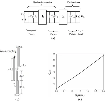
Figure 1. (a) Equivalent circuit of the proposed antenna; (b) The arrangement for the extraction of the input/output external quality factor (unit: mm); (c) The curve of the external quality factor Qe1 with respect to gapS1.
where Qe1 and Qe3 are the input/output external quality factor; FBW is the fractional bandwidth of the BPF; M1,2 and M2,3 are the coupling coefficient between the adjacent resonators. In our design, the coupling coefficient and external quality factor are calculated to beQe1 =Qe3 = 44.3 and
M1,2 = M2,3 = 0.0197, respectively. The corresponding bandpass equivalent circuit is demonstrated in Figure 1(a), and the element values are given as follow: L1 = LA = 2.46 nH, C1 =CA = 2.426 pF,
C2= 4.855 pF,L2= 1.23 nH, RA=RS= 50 Ω,J1 =J2 = 3.77 mS.
The full-wave electromagnetic simulator was utilized to extract the desired quality factor and coupling coefficient. The circuit is built on the substrate with dielectric constant of 2.94 and thickness of 1.27 mm. An arrangement for the extraction of input/output external quality factorQe1 is shown in Figure 1(b).
The size of the resonator is also demonstrated in Figure 1(b), while the length of the coupled section between Port1 and microstrip resonator is fixed at 22.4 mm. The curve of the extractedQe1 varied with respect to gap S1 is shown in Figure 1(c).
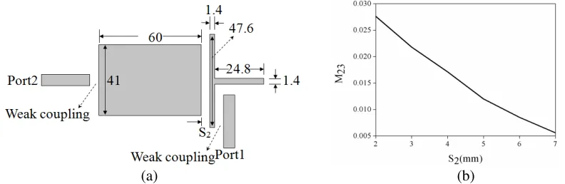
Similarly, the coupling coefficient of the dual-mode resonator can also be extracted, as shown in Figure 2(a). The coupling coefficient varied with respect to the length (L) of the open circuited stub is plotted in Figure 2(b). From Figure 2(b), the desired coupling coefficient M12 is readily satisfied when
(a) (b)
Figure 2. (a) An arrangement for extracting the coupling coefficient M12 (unit: mm); (b) The curve of the extracting coupling coefficientM12.
2.2. Design of Filtering Antenna
As shown in Figure 1(a), the patch antenna is designed to replace the resonator composed ofLAandCA and the load resistance of BPF. In order to ensure the filter characteristics, it is necessary to make sure
(a) (b)
Figure 3. (a) An arrangement for extracting the quality factorQe3 of the patch antenna (unit: mm); (b) The curve of the extracting external quality factorQe3.
(a) (b)
h = 1.27 mm. The optimized layout is illustrated in Figure 5(a), and a photograph of the fabricated antenna is shown in Figure 5(b). The simulated and measured results of the filtering antenna are shown in Figure 6. As can been seen from Figure 6(a), the measuredS11 is below−10 dB from 2.036 GHz to 2.084 GHz, which indicates that the fractional bandwidth is 2.33% with central frequency of 2.06 GHz.
(a) (b)
Figure 5. (a) The layout of proposed filtering antenna (unite: mm); (b) The photograph of the fabricated antenna.
(a) (b)
(a) (b)
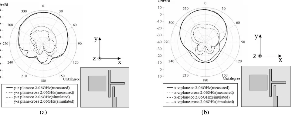
Figure 7. The simulated and measured radiation patterns: (a)y-z plane; (b) x-z plane.
The measured reflection zeros are not clear, which might be caused by the fabrication tolerance. As seen from Figure 6(a), the bandwidth of the proposed antenna is about three times wider than that of the traditional rectangular patch antenna. The measured gain varies within 1.0 dB over the passband with the maximum gain of 7.27 dBi, as shown in Figure 6(b). Meanwhile, the measured y-z and x-z plane radiation patterns at 2.06 GHz are drawn in Figures 7(a) and (b), respectively.
4. CONCLUSION
A novel filtering antenna composed of a dual-mode resonator and a rectangular patch radiator is proposed. The design process is based on filter synthesis method of 3rd-order Chebyshev BPF. The antenna work not only as a radiating element, but also as the resonator composed of LA and CA and load of the BPF. The measured results of the proposed structure agree well with the simulated ones, which indicates its good performance, including flat gain response within the passband, etc.
REFERENCES
1. Troubat, M., S. Bila, M. Th´evenot, et al., “Mutual synthesis of combined microwave circuits applied to the design of a filter-antenna subsystem,” IEEE Transactions on Microwave Theory and Techniques, Vol. 55, No. 6, 1182–1189, 2007.
2. Lee, J.-H., N. Kidera, S. Pinel, et al., “Fully integrated passive front-end solutions for a V-band LTCC wireless system,” IEEE Antennas Wireless Propagation Letters, Vol. 6, 285–288, 2007. 3. Wu, C.-H., C.-H. Wang, S.-Y. Chen, et al., “Balanced-to unbalanced bandpass filters and the
antenna applications,” IEEE Transactions on Microwave Theory and Techniques, Vol. 56, No. 11, 2474–2482, 2008.
4. Luo, G. Q., W. Hong, H. J. Tang, et al., “Filtenna consisting of horn antenna and substrate integrated waveguide cavity FSS,” IEEE Transactions on Antennas and Propagation, Vol. 55, No. 1, 92–98, 2007.
5. Queudet, F., B. Froppier, Y. Mahe, et al., “Study of a leaky waveguide for the design of filtering antennas,”33rd European Microwave Conference, 2003, 943–946, 2003.
6. Froppier, B., Y. Mahe, E. M. Cruz, et al., “Integration of a filtering function in an electromagnetic horn,”33rd European Microwave Conference, 2003, 939–942, 2003.