Design of High Capacity and Metro Core
Network and Performance Analysis
C. Parimala1, Dr. T. Sreenivasulu Reddy2
M.Tech, Dept. of E.C.E., S.V.U College of Engineering, Tirupati, Andhra Pradesh, India1 Professor, Dept. of E.C.E., S.V.U College of Engineering, Tirupati, Andhra Pradesh, India2
ABSTRACT: Coarse wavelength division multiplexing (CWDM) refers originally to optical signals multiplexed within the 1550 nm, which are effective for wavelengths between approximately 1280 –1610 nm (S band, C- band and L band) that enable to increase throughput by minimizing an investment in medium. This paper deals with the twin concepts of optical transport networking and coarse wavelength division multiplexing. Optical networking concepts like CWDM components, Network elements, designing and configuration of network, wavelength routing, and wavelength conversion are explained in detail. With the increasing deployment and growth in transport networks based on CWDM technology, solving the classic network design and planning problem of optimizing cost and scalability for given traffic requirements becomes ever critical. The concept is implemented in CWDM network to increase the scalability of the network and it is optimized through Bit error ratio (BER) and Optical signal to noise ratio (OSNR). Finally network gets extended in coverage area and maximizing bandwidth by ensuring the performance parameters of CWDM network such as latency, reliability, signal to noise ratio.
KEYWORDS: Multiplex, Optical transport network, Wavelength division multiplexing, latency, Bit error rate, Optical signal to noise ratio.
I. INTRODUCTION
The concept of combining many signals of different wavelength in a single optical fiber is called as the Wavelength Division Multiplexing (WDM). It has different types such as Broad WDM, Coarse WDM and Dense WDM. The CWDM system has major advantage in today’s data needs by transmitting signals at higher data rate. In this system network available at sufficient bandwidth capacity. In addition to the stability required for DWDM sources such as mux/demux and add/drop modules used in the systems also need to have very narrow filtering or wavelength separating characteristics that stay stable over a considerable temperature range. These filters are required to have very stringent tolerance and are difficult to fabricate, thus making these components inherently expensive [1]. In this system, the spacing between channel wavelengths is large, so that the requirements and tolerances for components and modules are more relaxed. Less-stringent tolerances result directly in substantial cost reduction of system as compared that of with DWDM system. The price differential makes it very attractive for this system can be used in the Metro Area Network (MAN) applications where the cost is most sensitive to subscribers. The system has channel spacing at wavelength 20 nanometres (nm) apart, compared with 0.4 nm spacing for DWDM. This allows the use of low-cost,uncooled lasers for CWDM.
The existing system is Synchronous Digital Hierarchy (SDH) and Time Division Multiplexing (TDM) can be operated for voice traffic and not for the high speed data traffic [2]. In order to support this need, very intelligent all-optical network device should be developed which will combine the features of SDH and the bandwidth increasing property of CWDM. The concept of optical fiber switching, loss control, packet switching and network topologies and synchronization has major role in the measure of throughput of the network.
Vol. 5, Issue 1, January 2017
lower precision, this system is less expensive and consumes less power than a DWDM system. However, the maximum realizable distance between nodes is smaller with CWDM [4].
II.LITERATUREREVIEW
A. Fumagalli, I. Cerutti, M. Tacca, D. Montgomery, I. Chlamtac and K. Pathak. [5] They discussed Trans-layer dense wavelength-division multiplexing network optimization. DWDM network optimization and management problems include routing and wavelength assignment, protection switching, and resource allocation. A novel reduction technique in conjunction with a tested design tool, CATO, allows optimization of significantly larger networks. However, it could not handle large optical networks.P. Castoldi', p.Ghelfil, L.Valcarenghil, G. Franzl, . [6] They demonstrated about The Design of Reliable Metro Core Networks. In this study the design of reliable network topologies is applied to the increasing amount of traffic, ring topologies represent a less attractive solution and on the other hand, highly connected DWDM mesh networks are required to grant the required level of throughput for bandwidth demanding applications and services. In addition results show that well connected DWDM mesh networks are required to successfully support high data-rate applications and services. Moreover, the results
drive the consideration that, in case of bigger cities or increasingly higher average bandwidth per customer,
the adoption of advanced technologysolutions, such as links with 80 wavelengths per link (at 10 Gbps) or
higher bit rates per wavelength (i.e., 40 Gbps), is required. A. Aloisio, F. Ameli, A. D'Amico, R. Giordano, G. Giovanetti and V. Izzo.[7] They described Performance analysis of a DWDM optical transmission system. It’s an optical technology which allows transmitting across a fiber many wavelengths, which can be added and dropped by means of passive optical components. The network is used for data transmission system that will find an application in the NEMO underwater neutrino telescope. The behaviour of the network is evaluated in the final arrangement by means of Bit Error Ratio and Optical Signal to Noise Ratio measurements at 800 Mb/s rate. The capable of data rates up to 1.4 GB/s and specifically designed for real-time data acquisition systems. The performance gets worse with respect to the system without amplification and this is reasonable because of the higher noise level introduced by the Raman amplifier into the receiver bandwidth.
III. CWDM SYSTEMS
The figure 1 shows the typical CWDM networking components.
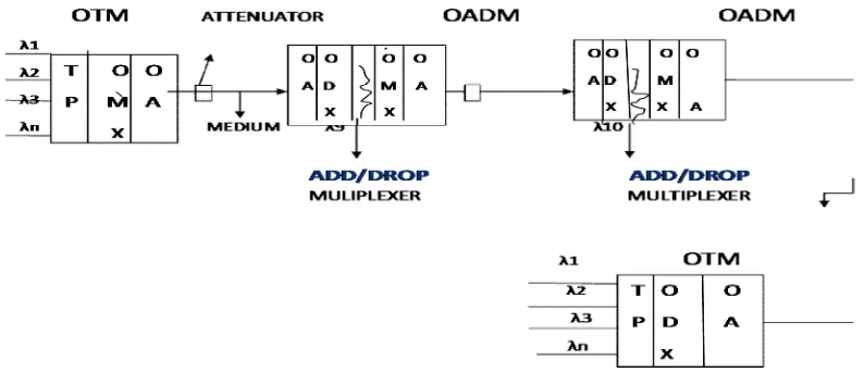
Fig 2: Components of CWDM
Figure 2 shows the components of CWDM. The major components include Optical Terminal Multiplexer (OTM), Optical Add Drop Multiplexer (OADM), Optical Booster Amplifier (OBA) and Optical Supervisory Channel (OSC).
A. OPTICAL TERMINAL MULTIPLEXER: It consists of
Optical Transponder Unit (OTU): A transponder is the element that sends and receives the optical signal from
a fiber. Transponder is typically characterized by its data rate and the maximum distance the signal can travel.
Optical Multiplexer Unit (OMU): Optical Multiplexer modules support ITU-T G694.2 and its wavelengths
between 1270nm to 1610nm in 20nm increments. They are protocol and rate transparent allowing up to sixteen services up to 10Gbps each to be transported across the same fiber link. CWDM MUX modules are designed to be integrated with other media converters and transponders to provide a true multi-service platform capable of delivering Ethernet, TDM, SONET and other services across a single-fiber or fiber pair CWDM common link
.
Optical De-multiplexer Unit (ODU): The main function of an optical demultiplexer is to receive from a fiber a
beam consisting of multiple optical frequencies and separate it into its frequency components, which are coupled in as many individual fibers as there are frequencies. A optical multiplexer functions exactly in the opposite manner. It receives many optical wavelengths from many fibers and converges them into one beam that is coupled into a single fiber.
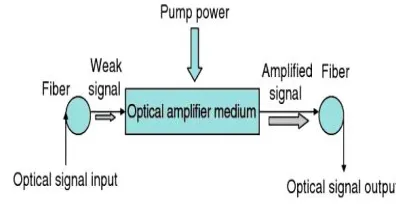
Optical Amplifier (OA): An optical amplifier is a device that amplifies an optical signal directly, without the
need to first convert it to an electrical signal. An optical amplifier may be thought of as a laser without an optical cavity, or one in which feedback from the cavity is suppressed. Optical amplifiers are important in optical communication and laser physics. Amplification is achieved by stimulated emission of photons from doping ions in the doped fiber [8]. Figure 3 shows an optical amplifier.
Fig 3: Optical Amplifier
B. OPTICAL ADD-DROP MULTIPLEXER
Vol. 5, Issue 1, January 2017
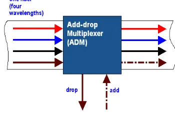
band, allowing either legacy 1310nm services or lower band CWDM wavelengths to be added and dropped from the common fiber. Figure 4 shows optical Add/Drop multiplexer.
Fig 4: Optical Add/Drop Multiplexer
C. OPTICAL BOOSTER AMPLIFIERS
The Booster Amplifier shows the characterization of a booster/power amplifier setup in a single erbium-doped fiber stage heavily doped, bi-directionally pumped by two 980 nm pump lasers. A large signal input power is considered in this case, since high signal input helps to produce high output power, which is necessary to booster/power amplifiers. It is important to mention that typical configurations of booster amplifiers include multiple Er-doped fiber stages [8].
D.OPTICAL SUPERVISORY CHANNEL
The Optical Supervisory Channel (OSC) is an additional wavelength usually outside the EDFA amplification band (at 1510 nm, 1620 nm, 1310 nm or another proprietary wavelength). The OSC carries an additional wavelength usually outside the EDFA amplification band (at 1510 nm, 1620 nm, 1310 nm or another proprietary wavelength) and it receives local information before retransmission. The optical supervisory channel provides transport of Order Wire, two E1 and one Ethernet Data (user proprietary) NMS data.
IV. IMPLEMENTATION
The implementation of CWDM technique in simulation is done by the software named Opti-system developed by Optiwave. This tool allows us to design, plan and test our optical network for different elements. This tool has variety of devices of about twenty testing instruments, twenty two Lasers for input to the system, more than 50 modulation techniques. Based on our requirement of the optical network design we can make avail of the devices from the software. It is the comprehensive design software suite allows us to design, plan, and test and simulate modern optical network in transmission layer of the network. The design of a CWDM network can be made effective by observing the parameters like Bit Error rate, latency, throughput, reliability. We use the test instrument tools like BER analyzer, WDM analyzer, Power meter, Spectrum Analyzer for our design. The power meter is used to measure the average power of the optical signal transmitted. The spectrum analyzer is used to plot the wave of magnitude of the input signal and frequency. The WDM analyzer used to measure the values like Signal to noise ratio, Signal power and noise power.
V. DESIGN
The network of CWDM technique for different input wavelengths can be implemented. The figure 5 shows 16 lambda CWDM network. The design goal is to achieve the transmission power and receive power of about +18±3 dB. The design has three sections, first is the transmitter part (OTM), then Add drop multiplexer, and the receiver part (OTM). The communication is through the optical fiber with the length of 80km and with spacing 20nm.
In BER analyzer the output less than 10-6 is good and less than 10-9is excellent quality of signal. In this we can increase the distance than the present system by using OADM, by this we can increase the quality and throughput of the signal.
Fig 5: Design of 16 lambdas CWDM network.
VI. RESULT
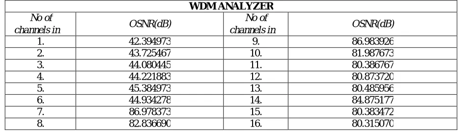
The output of 16 lambdas with OADM in WDM analyzer, OSNR values should be greater than 40db as shown in following Table1.
WDM ANALYZER
No of
channels in OSNR(dB)
No of
channels in OSNR(dB)
1. 42.394973 9. 86.983926 2. 43.725467 10. 81.987673 3. 44.080445 11. 80.386767 4. 44.221883 12. 80.873720 5. 45.384973 13. 80.485956 6. 44.934278 14. 84.875177 7. 86.978373 15. 80.383472 8. 82.836690 16. 80.315070
Vol. 5, Issue 1, January 2017
The output of 16 lambdas with OADM in BER analysis displays the quality of the signal should be less than 10-6 is good and less than 10-9is excellent quality of signal as shown in the following fig 7.
Fig7: BER analyzer with OADM
VII. CONCLUSION
This paper gives the brief discussion about the CWDM technique, its components and design of the network with efficient transmission of power. The bit error ratio is also analyzed. Since there is a need for huge data rate, this technique with enormous number of advantages and application act as the base for the future communication needs. As stated above, this technique along with the current technique of SDH will have an absolute effective network formation to handle the increasing data rate. The design of fiber optic for a distance of more than 100 km with a bandwidth 100 Gb/s by adding add/drop features. Thus, CWDM technique is the most important milestone for the communication background in order to meet the huge demand of data rate.
VIII. ACKNOWLEDGEMENT
The authors would like to thank Mr.A.Vetrivel, S.D.E., BSNL Regional Telecom Training Center, Chennai for providing the permission and technical assistance.
REFERENCES
1. WIKIPEDIA https://en.wikipedia.org/wiki/Wavelength-division_multiplexing#Coarse_WDM.
2. Gerd Keiser, Optical fiber Communications, 3rd edition, 2003.
3. John Wiley & Sons, Fundamentals of Photonics, 3rd edition, 2002.
4. Govind P Agrawal,Fiber Communication Systems, 3rd edition, 2002.
5. A.Fumagalli, I. Cerutti, M. Tacca, D. Montgomery, I. Chlamtac and K. Pathak. “The trans-layer dense wavelength-division multiplexing
6. P. Castoldi, p.Ghelfil, L.Valcarenghil, G. Franzl, “Design of Reliable Metro Core Networks” , ICTON '07,9th International Conference on
Transparent Optical Networks,2007.
7. A. Aloisio, F. Ameli, A. D'Amico, R. Giordano, G. Giovanetti and V. Izzo, "Performance analysis of a DWDM optical transmission system”.
Real Time Conference (RT), 17th IEEE-NPSS, 2010.
8. https://en.wikipedia.org/wiki/Optical-amplifier.
9. R.Ramasami and K.Sivaranjan, Optical Networks (Morgan, San Francisco, 2009).
10. E.Deservire, Erbium Doped Fiber Amplifiers: principles and Applications, Wiley, 1994.
11. J.G.Proakis, Digital Communication, 4th Ed.,McGraw-Hill,2000.