Abstract— The impact caused by the explosion of the pyrotechnic device used for stage separation of a launch vehicle and for satellite separation is called pyroshock. Pyroshock causes high-frequency, high-amplitude shock energy, which causes damage to electronic equipment situated close to the pyrotechnic device. Therefore, the electronic equipment mounted on a satellite has to satisfy the requirements of the Shock Response Spectrum(SRS) for pyroshock. As pyrotechnic device is costly and hazardous, mechanical pyroshock simulation devices can be used in pyroshock testing.
Metal-metal impact methods are utilized to simulate mechanical pyroshock, and to adjust the knee frequency of the shock response spectrum through resonant plates. However, it is difficult to predict the impact force history of metal-metal impacts and the dynamic behavior of resonant plates. Therefore, devices that satisfy the shock response spectrum are designed through experimental trial and error and much cost and effort is required. Accordingly, to reduce the cost and effort required in the initial design of a pyroshock simulation device, the shock response spectrum should be easily predictable.
In this paper, pyroshock was simulated through a pendulum impact device. In order to predict the shock response spectrum without difficulty, impact force history according to the mass and velocity of an impactor was represented by specific variables. An interpolation method and an extrapolation method based on experiment data were used to predict impact force history according to impact mass and velocity. Having determined the predicted impact force history, the dynamic behavior of a resonant plate and the shock response spectrum were calculated by performing finite element analysis (FEA). The predicted shock response spectrum findings were compared with experiment results.
Index Terms—Impact force history, Pyroshock simulation
Shock response spectrum, Transient response analysis
Manuscript received March 20, 2018; revised April 16, 2018. This work was supported by the Ministry of Science, ICT & Future Planning, Republic of Korea.
M. G. Kim is with the Chungnam National University, Daejeon, Republic of Korea (e-mail: [email protected]).
I. G. Kim is with the Chungnam National University, Daejeon, Republic of Korea (corresponding author +82-42-821-6684; fax: +82-42-825-9225; e-mail: [email protected]).
E. S. Go is with the Chungnam National University, Daejeon, Republic of Korea (e-mail: [email protected]).
M. H. Jeon is with the Chungnam National University, Daejeon, Republic of Korea (e-mail: [email protected])
M. S. Kang is with the Chungnam National University, Daejeon, Republic of Korea (e-mail: [email protected])
J. S. Choi is with Korea Aerospace Research Institute, Daejeon, Republic of Korea (e-mail: [email protected]).
I. INTRODUCTION
HE impact caused by the explosion of the pyrotechnic device used for stage separation of a launch vehicle, fairing separation, and satellite separation is called pyroshock. Pyroshock causes rapid acceleration at an extremely short period of time, and a large high frequency stress wave is generated. Pyroshock does not cause damage to the structure of launch vehicle, however, it can cause damage to electronic equipment, such as satellite electric boxes. In order to prevent pyroshock damage, the electronic equipment to be mounted on vehicle are required to be designed and manufactured considering pyroshock, In addition, pyroshock testing of the electronic equipment is necessary. Pyroshock tests have to satisfy the Shock Response Spectrum (SRS) required by a launch vehicle[1].
As pyrotechnic devices is costly and hazardous, a mechanical pyroshock simulation device that can simulate pyroshock is used. The mechanical shock simulator consists of an impactor and a resonant structure. Additionally, it should generate acceleration in a specific frequency band similar to the required pyroshock. At the same time, additional damage cause by high acceleration in a high frequency band above the requirements generated by the standing and reflected waves of resonant structures should be avoided.
A metal-metal impact method can be utilized to manufacture a mechanical pyroshock device, and to adjust the knee frequency of SRS through a resonant plate. However, it is difficult to predict the impact force history of a metal-metal impact and the dynamic behavior of resonant plates. Therefore, a device that meets SRS is designed through experimental trial and error, and this requires much cost and effort. In order to reduce the cost and effort required in the initial design of a pyroshock simulation device, SRS should be easily predictable.
To design a mechanical pyroshock simulation device, a study was conducted to confirm the feasibility of pyroshock simulations and the predictability of impulse responses to improve excitation performances at high frequency bands [2]. Also, the design parameters of resonant plates affecting pyroshock have been determined [3], and SRS changes according to impact characteristics have been identified [4]. In other studies, the impact response spectra of a specific structure were predicted using a commercial finite element analysis program employing a mechanical pyroshock simulator [5, 6]. Impact force has been calculated using
A Simple Approximate Method for Predicting
Impact Force History and Application to
Pyroshock Simulation
Mun-Guk Kim, In-Gul Kim, Eun-Su Go, Min-Hyeok Jeon, Min-Song Kang, Jeong-Su Choi
contact law and compared with experiment data [7]. A study was also undertaken to predict the impact force on structures [8]. Moreover, a study was conducted to predict the contact force on a plate subjected to a transverse load through the response of the structure [9]. In several studies, SRS of structures was predicted through experiments and analytical methods. In the above studies, impact force history was estimated using 1D modeling, 2D modeling or though experiments; calculating or obtaining impact force history by employing such methods was complex.
In this paper, pyroshock is simulated by a pendulum impact device. Impact force history and SRS are measured by running small-scaled pyroshock simulations. In order to predict SRS without difficulty, impact force history according to the mass and velocity of an impactor is represented by specific variables through experimental data. An interpolation method and an extrapolation method based on experiment data are used to predict impact force history according to impact mass and velocity. Using the predicted impact force history, the dynamic behaviors of a resonant plate are calculated by conducting finite element analysis (FEA) and SRS is obtained from the acceleration results of FEA. The calculated SRS is compared with SRS obtained from experiments.
II. SMALL SCALED PYROSHOCK SIMULATION
A. The Small-Scale Pyroshock Simulation Test
To obtain the impact force history and SRS of the resonant plate, a small-scale pyroshock simulation device was manufactured, as shown in Fig. 1. The resonant plate was an aluminum 6061 plate with a thickness of 15 mm. Acceleration was measured at 150 and 500 mm from the impact point. The in-plane impact force was applied to the resonant plate while varying the mass and impact velocity of the impactor, as shown in Table Ⅰ. The impact velocity was measured using a laser sensor. Impact force history and accelerations were measured by a force transducer_(PCB 208C05) and shock accelerometers(PCB 350D02), respectively. The force data sampling rate was 200 kS/s and the acceleration sampling rate was 51.2 kS/s. The impact tip was 25.4 mm in diameter and made of hemispherical steel. A anvil was attached to the impact point to protect the resonant plate. Experiments were also carried out under free free boundary conditions by placing a resonant plate on foam.
B. Impact Force History Results
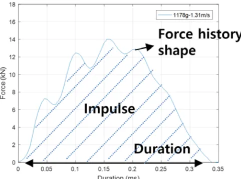
The small-scale pyroshock simulation tests were carried out three times for each case, and the impact force history was similar each time. The impact variables of the impact force history were maximum force, duration, impulse and force history shape, as shown in Fig. 2. The impact force history according to impact conditions are shown in Fig. 3. Specific variables are summarized in Table Ⅱ.
[image:2.595.303.544.362.541.2]As the mass increased, the duration of the force and the maximum force increased. As the velocity increased, the maximum force increased; however, the duration of the force was similar. The frequency band excited by the impactor in each condition was inversely proportional to the mass of the impactor and was proportional to the rigidity of the tip of the impactor.
Fig. 1. The small-scale pyroshock simulation device and resonant plate.
[image:2.595.322.533.583.751.2]Fig. 2. Impact force history and specific variables of the impact force history.
Fig. 3. Impact force history for impact conditions TABLE I IMPACT TEST CASE
Impact Mass Case Impact Velocity Case
347 g 1.31 m/s
601 g 1.94 m/s
[image:2.595.68.275.629.770.2]C. Shock Response Spectrum Results
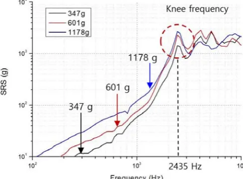
SRS for the different masses and velocities of the impactor are shown in Fig. 4 and Fig. 5. In the same resonant plate, the knee frequency was constant regardless of the impact condition, which was similar to the first natural frequency in the in-plane force direction of the resonant plate.
SRS depending on mass was proportional to the mass in the frequency band lower than the knee frequency; however, it was inconsistent in the frequency band higher than the knee frequency. SRS depending on velocity was proportional to the velocity in the whole frequency band.
III. FINITE ELEMENT ANALYSIS
The small-scale pyroshock resonant plate was modelled by MSC.PATRAN/NASTRAN, as shown in Table Ⅲ and Fig.6. The acceleration of the resonant plate was calculated according to the measured impact force history and by performing direct transient analysis.
To verify the FEA model, SRS predicted by FEA and SRS calculated using the pyroshock simulation tests were compared, as shown in Fig. 7.
It is considered that the error in the high frequency band was due to the error of the boundary conditions between the FEA model and the test model. The graph shows that the predicted SRS demonstrated striking similarities to the calculated SRS within ±3 dB in the whole frequency band.
Therefore, if impact force history can be predicted, SRS in a resonant plate can also be calculated through simple FEA.
[image:3.595.311.536.305.550.2]IV. IMPACT FORCE HISTORY PREDICTION Fig. 4. SRS for various impactor masses (impact velocity: 1.94 m/s)
[image:3.595.49.291.388.566.2]
Fig. 5. SRS for various impact velocities (impactor mass: 601 g)
TABLE Ⅲ FEA MODEL INFORMATION
Element 2D Shell
Element size 10 mm
Structure damping coefficient 0.05
Analysis time step 1/51200 s × 2560 = 0.05 s
Young’s modulus 70 GPa
Density 2691.7 kg/m3
[image:3.595.307.546.589.767.2]Fig. 6. FEA model
Fig. 7. Comparison of FEA and experimental SRS TABLE Ⅱ
IMPACT VARIABLES FOR IMPACT CONDITIONS
Impactor mass Impactor velocity Duration Impulse
347 g
1.31 m/s 0.200 ms 0.658 Nㆍs 1.94 m/s 0.185 ms 0.986 Nㆍs 3.01 m/s 0.170 ms 1.450 Nㆍs
601 g
1.31 m/s 0.250 ms 1.362 Nㆍs 1.94 m/s 0.245 ms 1.958 Nㆍs 3.01 m/s 0.235 ms 2.840 Nㆍs
1178 g
[image:3.595.45.289.596.776.2]A. A Simple Approximate Method
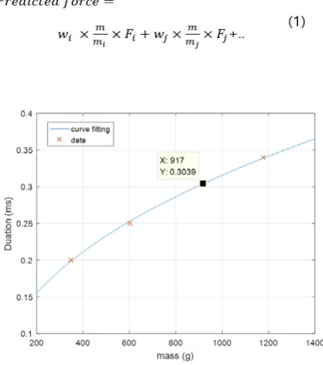
In order to predict the impact force history from the measured force history, the characteristics of the impact variables summarized in Table 2 were examined. Duration and impulse increased with increasing impactor masses and velocities. This is because momentum increases as mass and velocity increase. The change in momentum is the amount of impulse. Therefore, the relationship between duration and impulse according to mass was confirmed, as shown in Fig. 8 and Fig. 9. Duration and impulse according to mass were predicted by curve fitting.
Force history shape changes irregularly as mass increases. Force history shape is also important because some high frequency components of force shape excite high frequencies. Therefore, force history shape should be predicted. Force history is predicted as the ratio of measured force history to predicted force history as shown in (1). In addition, weighting values (wi, wj) are determined to satisfy impulse for any given velocity and mass.
First, the duration of the predicted impact force history is determined by the duration of the measured impact force history. Second, weighting values are given to the measured impact force history according to the mass ratio in order to approximately determine the force history shape.
B. Predicted Impact Force History and SRS
The predicted impact force history of 917 g mass(using measured 347 g, 601 g and 1178 g force history) and 1178g mass (using measured 347 g, 601 g and 917 g force history) using a simple approximate method were compared with the measured impact force history of 917 g and 1178 g, as shown in Fig.10 and Fig. 11. Although there were some errors, the predicted impact force history was similar to the measured impact force history.
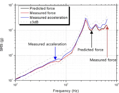
To predict SRS, the behavior of the resonant plate was predicted by conducting FEA using the predicted force history, as shown in Fig. 12 and Fig. 13. The graph shows that the predicted SRS was strikingly similar to the calculated SRS within ±3 dB in the whole frequency band.
[image:4.595.52.286.305.569.2]It was confirmed that SRS can be calculated by using predicted impact force history.
[image:4.595.318.543.379.558.2]Fig. 8. Duration in relation to impactor mass
[image:4.595.316.544.565.766.2]Fig. 9. Impulse in relation to impactor mass
Fig. 10. Comparison of predicted and experimental impact force history (917g – 1.31 m/s)
[image:4.595.54.289.588.772.2]V. CONCLUSION
In this paper, the impact force history and SRS of the impact conditions of a small-scale pyroshock simulation have been verified through experiments. If impact force history is accurate, it has been confirmed that experimental results are similar to SRS calculated by FEA. In order to predict accurate impact force history, the relations between impact force history and impact conditions should be firmly established. It was verified that the predicted impact force history was similar to the impact force history obtained in the experiments. Therefore, it is possible to calculate SRS by FEA using predicted impact force history. This method was verified by comparing predicted SRS with experimental SRS. In order to design a mechanical pyroshock simulation device that meets the required SRS in the initial design stage, a simple approximate method for impact force history is required. SRS can be predicted simply by using predicted impact force history. A resonant plate can be designed according to predicted SRS. Also, the mass of an impactor can be designed using the relationship between impact force history and impactor mass and velocity. These approaches to SRS prediction can reduce costs and time at the initial
mechanical simulated pyroshock testing stage.
In further work, impact force history and SRS for out of plate impacts should be examined. Also, impacts for plates with attached dummy masses such as electronic equipment should be predicted.
REFERENCES
[1] MIL STD 810 – Test Method Standard for Environmental Engineering Considerations and Laboratory Tests, US Department of Defense, 2000.
[2] Jeong, J. R., Kim, I. G., Lee, S. J., and Kang, C. H., “Characteristics of The Shock Response Spectrum for Structures Subjected to Pyroshock,”
Proceeding of the 2011 KSAS Spring Conference, pp.940-946, 2011.
[3] Go, E. S., Kim, I. G., Jeon, M. H., Kim, M., G., and Choi, J. S., “Predicting Dynamic Behavior of Pyroshock Simulated Device with a Small-Scaled Resonant Plate,” Proceeding of the 2017 KSAS Spring Conference, pp.97-98, 2017.
[4] Kim, M., G., Go, E. S., Kim, I. G., Jeon, M. H., and Choi, J. S., “Comparison of Shock Response Spectrum According to Impactor Property of Pyroshock Simulation Device,” Proceeding of the 2017 KSAS fall Conference, pp.87-88, 2017.
[5] Choi, J. M, An Estimation Method for the Shock Response Spectrum Using a Pyroshock-simulataed Resonator at Structures, MS Thesis,
Department of Aerospace Engineering, Chungnam National University, 2010.
[6] Jonsson, Martin. Development of a shock test facility for qualification of space equipment. MS Thesis. Chalmers University of Technology,
2012.
[7] Lacher, A., Jüngel, N., von Wagner, U., & Bäger, A. "Analytical calculation of in-plane response of plates with concentrated masses to impact and application to pyroshock simulation." Journal of Sound and Vibration, 331(14), pp,3358-3370, 2012.
[8] Wang, B-T. "Prediction of impact and harmonic forces acting on arbitrary structures: theoretical formulation." Mechanical Systems and Signal Processing, 16(6), pp.935-953, 2002.
[image:5.595.47.286.57.233.2][9] Doyle, James F. "Determining the contact force during the transverse impact of plates." Experimental Mechanics 27(1), pp.68-72, 1987.
Fig. 12. Comparison of predicted SRS by predicted force history FEA, predicted SRS by measured force history FEA and experimental SRS
(917g – 1.31 m/s)
Fig. 13. Comparison of predicted SRS by predicted force history FEA, predicted SRS by measured force history FEA and experimental SRS
[image:5.595.50.286.274.457.2]