MNRAS487,3971–3989 (2019) doi:10.1093/mnras/stz1462 Advance Access publication 2019 June 5
Radio source extraction with P
RO
F
OUND
C. L. Hale ,
1‹A. S. G. Robotham ,
2‹L. J. M. Davies ,
2M. J. Jarvis ,
1,3S. P. Driver
2and I. Heywood
1,41University of Oxford, Denys Wilkinson Building, Keble Road, Oxford, OX1 3RH, UK
2International Centre for Radio Astronomy Research (ICRAR), University of Western Australia, Crawley, WA 6009, Australia 3Department for Physics, University of the Western Cape, Bellville 7535, South Africa
4Department of Physics and Electronics, Rhodes University, PO Box 94, Grahamstown 6140, South Africa
Accepted 2019 May 20. Received 2019 May 3; in original form 2018 November 13
A B S T R A C T
In the current era of radio astronomy, continuum surveys observe a multitude of objects with complex morphologies and sizes, and are not limited to observing point sources. Typical radio source extraction software generates catalogues by using Gaussian components to form a model of the emission. This may not be well suited to complicated jet structures and extended emission, particularly in the era of interferometers with a high density of short baselines, which are sensitive to extended emission. In this paper, we investigate how the optically motivated source detection package PROFOUND(Robotham et al.2018) may be used to model radio emission of both complicated and point-like radio sources. We use a combination of observations and simulations to investigate how PROFOUNDcompares to other source extractor packages used for radio surveys. We find that PROFOUNDcan accurately recover both the flux densities of simulated Gaussian sources as well as extended radio galaxies. PROFOUNDcan create models that trace the complicated nature of these extended galaxies, which we show is not necessarily the case with other source extraction software. Our work suggests that our knowledge of the emission from extended radio objects may be both over or under-estimated using traditional software. We suggest that PROFOUNDoffers a useful alternative to the fitting of Gaussian components for generating catalogues from current and future radio surveys. Furthermore, PROFOUND’s multiwavelength capabilities will be useful in investigating radio sources in combination with multiwavelength data.
Key words: methods: data analysis – radio-continuum: galaxies, general.
1 I N T R O D U C T I O N
Modern radio surveys are able to combine deep and wide-area observations of the sky with greater ease than ever before. Radio facilities and the extragalactic surveys they perform such as from
MeerKAT (Jarvis et al. 2016; Jonas & MeerKAT Team 2016),
Australian SKA Pathfinder (ASKAP; Johnston et al.2008; Norris
et al.2011), the Very Large Array (VLA; Helfand, White & Becker
2015; Smolˇci´c et al.2017), LOw Frequency ARray (LOFAR; van
Haarlem et al. 2013; Shimwell et al.2017) and the Murchison
Widefield Array (MWA; Tingay et al. 2013; Wayth et al.2015;
Hurley-Walker et al.2017) are transforming our view of the radio
skies. The increased field of view, resolution, and surface brightness sensitivity of these observations allows a wide variety of complex and interesting morphologies to be observed. These include Active
E-mail:[email protected](CLH);aaron.robotham@uwa. edu.au(ASGR)
Galactic Nuclei (AGN) of Fanaroff–Riley Type I and II (FRI and
FRII; Fanaroff & Riley1974) morphologies, radio relics, bent-tailed
radio sources, as well as a large number of radio-quiet quasars and Star-Forming Galaxies (SFGs).
With the advent of these new surveys, we are likely to observe emission that was previously unseen or unresolved, presenting more complicated morphologies than simple point sources. With this, it is important that the software used to model and generate the flux
density of sources is accurate. Current software such as PYBDSF
(Mohan & Rafferty 2015) and AEGEAN (Hancock et al. 2012;
Hancock, Trott & Hurley-Walker2018) fit Gaussian components to
radio sources to form a catalogue. For simple unresolved emission, this involves fitting single Gaussian components. For resolved sources and those with extended emission and more complicated jet morphology, these are fit using a combination of Gaussian components of different sizes which are joined together to form a final source.
Whilst modelling emission with Gaussian components works well for point sources, it is not necessarily true that larger galaxies
2019 The Author(s)
At other wavelengths, source extractors such as SEXTRACTOR
(Bertin & Arnouts1996) and PROFOUND(Robotham et al.2018)
use pixel extraction of emission. SEXTRACTORhowever, does use
ellipses to determine the total photometry whereas PROFOUNDdoes
not rely on forcing a shape to model the source and extract fluxes. This is advantageous at optical wavelengths as galaxies have com-plicated structures consisting of combinations of bars, discs, spiral arms, etc. The data at these wavelengths also have the advantage that the noise is less correlated and so it is easier to distinguish a galaxy detection from noise. This is more complicated for radio data where the noise is highly correlated and has Gaussian structure in it that can appear similar to real emission. This could suggest that pixel flooding detection algorithms may be less advantageous in these cases or that harsher detection criteria would be needed. This is one of the reasons that fitting Gaussian components to sources has dominated how we extract information from radio images.
In this paper, we investigate whether PROFOUND(Robotham et al.
2018) can be used as a source extractor for radio surveys, and the
advantages it may have. PROFOUNDhas been used previously with
optical (Turner et al. in preparation) and near-IR (Davies et al.
2018; Robotham et al.2018) observations. PROFOUND will not
only be especially useful for those galaxies that consist of resolved emission with more complicated shapes but also is designed with multiwavelength galaxy studies in mind. Source information from other wavelengths can be used as a proxy for detection in another band. In the radio, for example, relationships between star formation
and radio luminosity (Bell2003; Garn et al.2009; Davies et al.2017)
could be useful as proxies for radio emission. This is especially useful for future studies of galaxies, where we are ever more reliant on multiwavelength observations.
In this paper, we first give a brief overview of the package
PROFOUND and the data we use to test it in Section 2 before
investigating how well it performs on a range of radio data. First,
we compare how well PROFOUNDperforms on radio continuum
imaging of the XMM–LSS field (Heywood et al. in preparation) in
Section 4. Next, we investigate how well PROFOUNDcan recover
simulated galaxies that are not limited to point sources, and include extended Gaussians, ‘disc’ like objects, and those with jet emission, in Section 5. Finally, in Section 6, we also investigate its use on sources with known complicated jets using a handful of 3C AGN
(from Leahy, Bridle and Strom1996). In all these comparisons,
we compare to two source detection algorithms that are widely
used in radio surveys, PYBDSF (Mohan & Rafferty 2015) and
AEGEAN (Hancock et al.2012,2018). We discuss the potential
uses and advantages of PROFOUNDin radio source extraction and
draw conclusions in Section 7.
those pixels which are above an assigned threshold of the rough sky model from step (i). The combined pixels which make up the source are known as a segment. Each segment includes the pixels that have started from the bright pixel which initiated the source and those pixels that have grown outwards from the bright pixel and remain above the threshold limit.
(iii) Use the source model to remove real emission and improve upon the sky model by repeating step (i).
(iv) For each source that has been defined, measure the properties. (v) Iterate the source finding and sky model defined in steps (i), (ii), and (iii) and dilate the segments to ensure the flux has converged to a tolerance level.
(vi) Measure the source properties of the final segments to create a final catalogue.
The segment identification and dilation process PROFOUNDuses
to generate sources involves selecting bright pixels (above a certain sky cut) which have not been assigned to a segment yet, then searching the pixels around each segment to see if they have sufficient flux to also contribute to the source. The fact that it can grow pixels in any direction means that no morphology is assumed, this is important for extracting fluxes of complex morphological shapes. It is not limited to certain shapes and so is more natu-rally able to model complicated emission. This source extraction method is known to work successfully in the optical and near-IR regimes where it is easier to determine the bright emission from sources.
In radio images however, the Gaussian noise peaks and troughs can be misidentified as sources. This is due to the fact that the image is convolved with the point spread function (PSF) which can be complicated due to the incomplete aperture. As such, source extraction software used on radio images have typically used Gaussian components with a threshold for the peak flux density
per beam above a high-σ level (typically 5σ, where σ is the
rms). The pixel flux density per beam values are then extracted
out to another sigma level (typically 3–4σ) and the emission is
modelled as a Gaussian. These high-σ limits are used to eliminate
the false detection of noise as sources. However, for bright sources with extended jet structures that we observe from radio AGN and extended emission, these are unlikely to be well represented by large
Gaussian shapes. This is where the benefit of using PROFOUNDmay
lie.
Radio source extraction with P
ROF
OUND3973
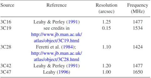
Table 1. Information on the 3C observations that have been used in Section 6. For each source, the resolution, frequency, and reference are given (from Leahy, Bridle and Strom1996).
Source Reference Resolution Frequency
(arcsec) (MHz) 3C16 Leahy & Perley (1991) 1.25 1477 3C19 see credits in
http://www.jb.man.ac.uk/
0.15 1534
atlas/object/3C19.html
3C28 Feretti et al. (1984); 1.10 1424
http://www.jb.man.ac.uk/ atlas/object/3C28.html
3C42 Leahy & Perley (1991) 1.20 1477
3C47 Leahy (1996) 1.00 1650
2.2 Radio data
2.2.1 VLA observations of the XMM–LSS field
Here, we make use of VLA observations of the XMM–LSS field at
1.5 GHz (Heywood et al. in preparation). This covers∼7.5 deg2with
the central region overlapping with the XMM–LSS field observed
in the VIDEO Survey (Jarvis et al.2013). This is a field with a
wealth of ancillary data across the electromagnetic spectrum (see,
e.g. Pierre et al. 2004; Tasse et al. 2007; Mauduit et al. 2012;
Davies et al.2018; Hale et al.2018). The observations being used
(Heywood et al. in preparation) were observed with 32 pointings
in B-Configuration. This reached a final rms of∼16μJy/beam at
4.5 arcsec resolution over the VIDEO field. For our investigation,
we make use of∼1.2×1.2 deg2of this field. This was chosen so
the central square degree overlaps with the CFHTLS Deep 1 Field
(CFHTLS D1; Cuillandre et al.2012; Hudelot et al.2012), centred
at (36.5◦,−4.5◦).
2.2.2 Observations of 3C sources
To investigate how well PROFOUND can model bright, extended
AGN with complex morphologies, we use observations of 3C
sources (Edge et al. 1959; Laing, Riley & Longair 1983). We
obtained images for five of the 3C sources from "An Atlas of
DRAGNs" (Leahy, Bridle and Strom1996), which has information
and images on 85 sources from the 3CRR sample (Laing et al.
1983). The five images used were from the first∼10 sources of
the listed sources,2they are: 3C16 (Leahy & Perley1991), 3C19
(seehttp://www.jb.man.ac.uk/atlas/object/3C19.html), 3C28
(Fer-etti et al.1984;http://www.jb.man.ac.uk/atlas/object/3C28.html),
3C42 (Leahy & Perley1991), and 3C47 (Leahy1996). We give
information on the resolution and frequency on these observations
in Table1. Our analysis is presented in Section 6.
3 S O U R C E D E T E C T I O N PA R A M E T E R S
In order to compare PROFOUND to other source extractors, it is
necessary to determine which parameters to use in order to make comparisons. We use two approaches to do this.
The first is to determine the skycut parameter which is
necessary for PROFOUND to be used and then compare these to
2As PROFOUNDdoes not support the NCP projection scheme, these were 5
sources that were isolated, not in this projection scheme, had large regions of source-free sky in the cut-out and gave a variety of morphologies.
the typical default parameters that are used for PYBDSF and
AEGEAN. Both PYBDSF and AEGEAN have been used in past
radio continuum observations (see, e.g. Hurley-Walker et al.2017;
Shimwell et al.2017) and have been compared to each other in
previous tests for large-survey data challenges (a comparison for use on simulated images in preparation for EMU was performed
in Hopkins et al.2015). This gives default parameters for PYBDSF
ofthresh isl = 3.0andthresh pix = 5.0. AEGEAN
used the parameters: floodclip = 4.0 and seedclip =
5.0.
The second is to compare how well the source extraction algorithms model sources when using parameters that have similar rates of false detections. This is to attempt to tailor the software to the VLA image in order to provide a more fair comparison to one another, where they have similar accuracy detecting real emission. We describe how we determined these parameters below.
3.1 PROFOUND
To decide on the necessary detection parameters for PROFOUNDwe
consider the false detection of sources. As mentioned previously, the correlated noise in radio data means that it is likely a threshold larger than used in optical and IR surveys will be necessary. We need to ensure that these sky cuts are not too extreme such that we are unable to flood the pixels to extract emission across the source.
skycuthere is the number ofσ(the sky rms) to be included in the
source. In order to determine whichskycutis appropriate with
these observations, we investigate how our false detection varies for
differentskycutvalues. This allows us to determine at which point
PROFOUNDbecomes limited by the correlated noise of the image
and is picking up too many noise spikes as sources.skycutis the
parameter in PROFOUNDwhich determines how manyσabove the
sky a pixel can contribute to the source segment. Varying this will determine both the number of sources as well as how many pixels are combined together to extract the total flux density of the source. For bright objects, the majority of this emission will be significantly
above the sky and so PROFOUNDwill measure its total flux density.
To quantify the false detection rate, we use the assumption that the noise in the image consists of Gaussian peaks and troughs that are symmetric. This symmetry means that a negative version of the image (from now on known as inverted) has the same noise properties as the non-inverted image, meaning large noise troughs in the original image are now detectable as sources. Hence, by
running PROFOUND(and the other software) on the inverted image,
the number of detected sources should be approximately equal to the number arising from false positive noise spikes in the true image. Using this, it is possible to constrain the percentage of ‘real’ detections in the image, as in Equation (1). By investigating how
the false detection varies withskycut(in steps of 0.5) this can
allow us to pick an optimum value ofskycutthat successfully
extracts sources with minimal contamination from noise.
% Real Detections=100×Nimage−Ninv.image
Nimage
(1)
The results from investigating the percentage of real detections
with PROFOUNDcan be seen in Fig.1, where the left-hand panel
(Fig.1(a)) shows the number of sources detected per square degree.
This is shown for both the image (red) as well as the inverted image (blue). The difference between the numbers detected in the original and inverted images is also shown (magenta). The right-hand panel
(Fig.1(b)) shows the percentage of real detections (as described in
Equation (1)) compared to theskycut.
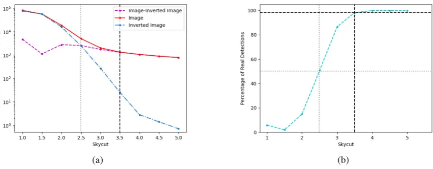
Figure 1. The false detection rate of sources with PROFOUNDwhen sources are extracted from the VLA image of the XMM–LSS field (Heywood et al. in preparation), described in Section 2.2.1. Shown in (a) is the number density of sources in the image (red) and the inverse image (blue) as a function of the PROFOUNDparameterskycut, as well as the difference between the red and blue lines (magenta); (b) the percentage of false detections as a function of skycut. For clarity, the grey dotted lines indicates where a 50 per cent percentage of real detections occur and the black dashed line indicates theskycutof 3.5, chosen for this investigation, at a false detection rate of∼2 per cent.
As expected, the percentage of real detections is near 100 per cent
for high-skycutvalues, where a conservativeσ cut is used. The
number of sources in the image that we believe to be real declines
sharply below askycut of 3.5. At askycutof 3.5, we have
a ∼98 per cent real detection percentage in our catalogues, this
declines to∼87 per cent at askycut=3 and to 50 per cent and
below forskycut<2.5. As such askycutof 3.5 is appropriate
to use with PROFOUNDon the data in order to minimize the number
of false detections. This is used in all future work unless otherwise
stated.3
We therefore use the following prescription in running PRO
-FOUNDon the radio images:
(i) Run a blind detection with PROFOUNDusing
profound-ProFound. Run this over the image usingskycut = 3.5and setgroupstats = TRUEandgroupby = ‘segim’. Each source is defined as a segment.
(ii) Using the grouped segments (group$groupim) and the
corresponding statistics (properties) for these segments from
groupstats, a catalogue of sources can be defined. Using the grouped segments ensures that any adjacent segments are combined and the source information for the merged segment is recorded within the source catalogue.
(iii) Apply a beam correction to convert between the map (in Jy/beam) to the total flux densities (in Jy).
Step (ii) ensures that neighbouring segments are
com-bined together. Having used groupstats = TRUE and
groupby = ‘segim’allows a segmentation map (a map of the segments) to be generated in which all segments that are touching are joined together into one single object. As segments are determined by bright emission, many locations within a single object could be defined as a separate segment. Due to the on-sky density of radio sources at these flux densities, we are unlikely to have emission that is adjacent but not from the same source. However, where data is confused due to the resolution and sensi-tivity of the observations, combining segments together may not
3We note that this value ofskycutwas appropriate here, but may not be
for data which has more contamination from e.g. sidelobes in the image.
be appropriate. Step (iii) corrects the flux densities in the extracted
PROFOUNDcatalogue from Jy/beam to Jy. This is a simple numerical
conversion which is applied after the source catalogue has been generated.
For steps (i) and (ii) we present the commands used in PROFOUND
to obtain the extracted catalogue, for clarity:
•image = readFITS(image file)
•image blind=profoundProFound(image, plot=FALSE, skycut=3.5, rotstats=TRUE, boundstats=TRUE, nearstats=TRUE,
groupstats=TRUE, groupby=‘segim’, ver-bose = TRUE)
•write.csv(image blind$groupstats, file=‘file name.csv’, quote=FALSE, row.names = FALSE)
To make the source model:
•segim model=image blind$group$groupim
•segim model[image blind$group$groupim!=0] =1
•segim model[image blind$group$groupim==0] =as.numeric(NaN)
•model=(image$imDat-image blind$sky)
∗segim model
Again, we note that in both existing and future observations
where the radio data is confused, usinggroupstats = TRUE
andgroupby = ‘segim’may not be appropriate, as the source density may be too high.
3.2 PYBDSF and AEGEAN
To make appropriate comparisons between the source detection
packages we also calculate the real detection fraction for PYBDSF
and AEGEAN. This is to choose parameters in both PYBDSF
and AEGEAN that give similar percentages of real detections to
Radio source extraction with P
ROF
OUND3975
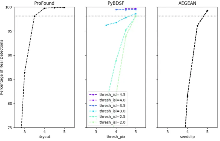
Figure 2. The percentage of real detections for the different source extraction software used when their respective detection parameters are varied. This is shown for PROFOUND(left), PYBDSF (centre), and AEGEAN (right).
3.2.1 PYBDSF
For PYBDSF, we only change the parametersthresh island
thresh pix. Of these parameters,thresh isldetermines the number of sigma that the boundary of the source can flood out to for the pixels to be included in the fitting. On the other hand,
thresh pixhelps to determine whether a source is included in
the catalogue. PYBDSF uses an absolute thresholding to quantify
whether a source is determined to be detected. This absolute
thresh-olding only includes sources in the final catalogue with fluxes>
thresh pix × rms + mean(map). As the mean map value
within an island is smaller ifthresh islis smaller, due to more
lower flux pixels in the source, more sources will be detected for
the samethresh pixbut with smallerthresh isl. Therefore,
for PYBDSF both thresh isl and thresh pix will affect
the number of false detections. Although other parameters can be changed, using the default settings and only varying the threshold limits should give a good comparison between the source extractors, as the complexities of varying all the parameters can be a long process and so most users are likely to only change a handful of
parameters. For PYBDSF, we output each source catalogue for the
different thresholds, where overlapping Gaussian components that
PYBDSF has designated to be part of the same source have been
combined together.4
As in Section 3.1, we construct the percentage of real detections
using PYBDSF but now as a function of thresh isl and
thresh pix(again in steps of 0.5). This can be seen in Fig.2
(middle panel). For PYBDSF, two parameters are varied and the
percentage of real detections for giventhresh pixvalues, with
varyingthresh islare shown in different colours ranging from
a value of 2 (light green) to 4.5 (purple) for PYBDSF. The black
dashed horizontal line in all three panels indicates the percentage
4seehttp://www.astron.nl/citt/pybdsm/algorithms.html#grouping-of-gauss
ians-into-sourcesfor how PYBDSF groups sources.
of real detections for the value of skycut that we use for
our PROFOUND detections. We plot these only for values where
thresh pix>thresh isl.
As can be seen in Fig. 2, to obtain similar
percent-ages of real detections for PYBDSF, then either values of
thresh isl/thresh pixof 2.5/5.0 or 3.0/4.5 should be used. The first of these combinations gives a percentage of real detections
most similar to that obtained with PROFOUND, however we choose
to use the 3.0/4.5 combination which has a lowerσ threshold. This
means that more sources will be detected, in this caseN3.0/4.5 ∼
1.1×N2.5/5.0more sources.
3.2.2 Extended emission with PYBDSF
We also consider using settings which allow PYBDSF to better
model extended structures in the image (for further information see http://www.astron.nl/citt/pybdsm/examples.html#image-with-extended-emission). To do this, we run PYBDSF with the settings
described previously but with alsoflagging opts = True,
flag maxsize bm = 100, atrous do = True,
rms map = False, mean map = ‘zero’. We will
refer to all tests using this as atrous do from now.
flag maxsize bm = 100 allows for large Gaussians, much
greater than the beam size, to be fit whilstatrous do = True
allows Gaussians of different scales to be fit. Setting
mean map = ‘zero’ ensures the background mean is set to 0, which is helpful if there is extended emission that could be misinterpreted as background.
3.2.3 AEGEAN
For AEGEAN, there are again two main parameters that we
consider changing, similar to PYBDSF these are floodclip
and seedclip. floodclip is similar to thresh isl and
seedclipis similar tothresh pix as used in PYBDSF. We
Figure 3. Example images of three extended morphology radio sources in the data (left-hand panel) and their corresponding modelled emission in PROFOUND
Radio source extraction with P
ROF
OUND3977
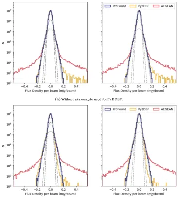
Figure 4. Histogram of the flux densities for the sources recovered in the source catalogues from PROFOUND(blue), PYBDSF (yellow) and AEGEAN (red). The number of objects in the catalogue from each source extractor is shown in the top left-hand corner of each panel. On the left-hand panel the results when the parameters determined in Section 3.2 are used and the right-hand panel shows this with the default parameters of PYBDSF and AEGEAN used to generate the source models. For the top panel (a) PYBDSF has theatrous dosetting off whilst it is used in the bottom panel (b).
again calculate the percentage of real detections, but this time as
a function ofseedcliponly (again in steps of 0.5). AEGEAN
has a fixed thresholding based solely on theseedclipvalue and
so whilstfloodclipwill determine the extent to fit sources to,
it will not affect the number of sources detected. This shown in
Fig.2(right-hand panel). A value ofseedclipbetween 4.5 and
5.0 seems appropriate for AEGEAN. As this does not depend on
floodclip, we use the default value of 4.0 for this. Although a seedclip of 4.5 has a slightly smaller real percentage fraction of
detections, this is still a high value ∼96 per cent. As a value of
seedclip=5.0 is the default value, we shall use here a value of
seedclip=4.5 as a comparison.
Now that the different parameters for the different source detec-tion software have been determined, we will use these parameters, unless otherwise stated. We shall compare in all cases both using the default parameters as well as the parameters from the real source
detection analysis.5
5We note that when comparing the false detections over the central square
degree only yielded the same detection parameters choice as determined here.
4 B L I N D D E T E C T I O N U S I N G T H E D I F F E R E N T S O U R C E E X T R AC T O R S
When PROFOUNDis run over the XMM-LSS image, 1360 sources
were found over the central 1 deg2 of this field.6 For the same
region PYBDSF found 1122 sources (1,332 using atrous do)
and 1192 with AEGEAN, when the default parameters were used. If we instead compare the catalogues for the parameters
based on thepercentage of real detections, PYBDSF found 1280
sources (1692 usingatrous do) where as AEGEAN found 1484.
Differences in these numbers will arise from differences in the detection depths of the different algorithms as well as differences in whether resolved sources have been split into multiple components.
As we feel that the benefits of PROFOUNDmay arise from its ability
to determine flux densities and models of sources with complicated
morphology and extended emission, we include images in Fig.3for
three of these extended sources. This is to compare the models from
PROFOUNDto PYBDSF and AEGEAN. These are shown when the
6That overlaps with the CFHTLS Deep 1 field.
Figure 5. Histogram of the residual images created by PROFOUND(blue), PYBDSF (yellow), and AEGEAN (red). A model of the noise in the image is also shown through a three Gaussian model (grey dotted, dashed and dot-dashed lines) with the sum of these three components shown in the thicker grey solid line. The left-hand panel shows the results when the parameters determined in Section 3.2 are used for source extraction and the right-hand panel shows this with the default parameters of PYBDSF and AEGEAN used to generate the source models. The top panel shows the residuals whenatrous dois not used in PYBDSF, whilst the bottom panel shows the results when theatrous dosetting is switched on.
default parameters of PYBDSF and AEGEAN and askycutvalue
of 3.5 for PROFOUNDwere used.
As can be seen from the examples in Fig. 3, PROFOUND,
in these cases, captures the shape of these sources that have
complicated morphologies. With AEGEAN and PYBDSF (without
atrous do) in the cases shown, parts of the source are not well modelled and do not capture the full shapes. This may be due to
over-fitting of components, such as in Fig.3(a) with PYBDSF or
due to under fitting of components, as in Fig.3(b). With PYBDSF
whenatrous dois used, these sources are much better modelled
and the extended emission is better captured, as seen in Figs3(b)
and (c). However, it is noticeable in3(a), that there can be thin,
extended haloes around these sources due to some of the Gaussian
components being fit. This is not the case with PROFOUND. The
residuals for PROFOUND(i.e. the sky background image (over the
segments) as the sources have been subtracted out) are smooth and
close to zero and do not show the noise structure that is shown
in the residuals from PYBDSF and AEGEAN. This is because the
sky is modelled as a smooth distribution and is subtracted from
the images. This means that in the case of PROFOUND, noise
sub-structure is likely to be contained within the model. However if the noise is symmetric over the source, it should approximately sum to zero and as such not affect the estimate of the total flux density, although this noise may affect the measured peak flux.
To compare how each software has extracted sources quantita-tively, we consider both the flux densities in the catalogues as well as the residuals of the images once the sources have been extracted. In terms of the total flux densities, we present a histogram of these
from the different source extraction software in Fig.4. This is again
Radio source extraction with P
ROF
OUND3979
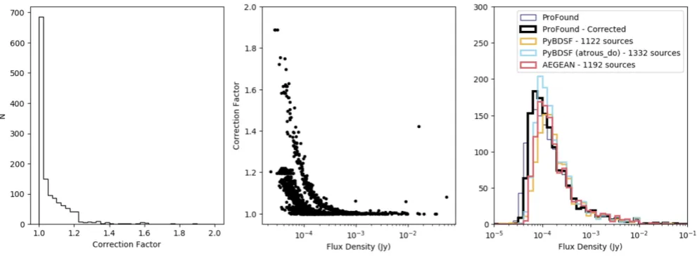
Figure 6. The correction factor applied to the blind detection to ensure they have fully sampled the beam. On the left-hand panel is a histogram of the correction factors that need to be applied to each source. The centre panel shows this correction factor as a function of flux density. The right-hand panel shows the source counts with the corrected source counts from PROFOUND(black), PROFOUNDwith no correction applied (thin, blue), PYBDSF (withoutatrous do, yellow), PYBDSF (withatrous do, light blue), and AEGEAN (red), when the default parameters are used.
are similar. The differences occur at lower flux densities where,
in both cases, PROFOUNDappears to preferentially detect fainter
sources compared to the other two detection algorithms. This is
likely due to the lowerskycutthat allows a source to be classified
i.e. using 3.5 compared to the 4.5/5σ peak detection threshold with
PYBDSF and AEGEAN. However, at∼10−4Jy, P
ROFOUNDappears
to be finding significantly fewer sources. This could suggest that
PROFOUND is being limited by not being able to probe the full
emission of a source over the beam area (if it is at low signal-to-noise), which may explain the large number of sources with faint
flux densities. If this is the case and PROFOUNDis unable to fully
sample the full beam, we can correct for this. This is discussed in Section 4.1.
The histogram of the residuals (across the entire image, not just
the central 1 deg2) from each model is also shown in Fig.5. If
all sources in the image have been extracted successfully then the residuals (image - model) should follow a Gaussian distribution. Any deviation from this suggests either an under or over-fitting of
sources. In Fig.5we show the results using the parameters from
Section 3.2 (left) default parameters (right) and also show the results
of using PYBDSF without (top) and with (bottom)atrous do
turned on. We also include, in Fig.5, a model for Gaussian noise
in the image by fitting the negative residuals (as these have less of
an excess tail) from PYBDSF as a Gaussian of variable amplitude
and σ. As the region of VLA image that we use for this work
is noisier at higher declinations due to primary beam corrections at the edge of the mosaiced pointings, we do not expect it to be perfectly modelled as a Gaussian. Due to this, the Gaussian noise is modelled as a combination of multiple (three) Gaussian components which can be seen by the dashed, dotted and dot–dashed lines. The combined noise model is shown in the thick grey line. The lowest
noise component fit here has a noise value of∼0.016 mJy/beam,
with the other components having noise levels of∼0.022 mJy/beam
and∼0.040 mJy/beam.
From Fig.5(a) it appears that the residuals from PROFOUNDand
also PYBDSF (withatrous doturned on) are much more similar
to a symmetric multi-Gaussian distribution than for PYBDSF
(with-outatrous do, Fig.5b) and AEGEAN. PROFOUNDand PYBDSF
(withatrous do) do not show the excess of positive residuals that
both PYBDSF and AEGEAN show. This suggests that PROFOUND
is able to successfully model sources in this field, and leaving only small residuals. The large number of positive residuals that remain
from AEGEAN and PYBDSF (withoutatrous do) suggest the
models are under-fitting the sources in the field. Withatrous do
switched on, PYBDSF has less excess positive residuals compared
to PROFOUND, but slightly more negative residuals. This suggests
that the residuals are not symmetric and may suggest an over fitting
of sources with PYBDSF.
4.1 Beam correction
As mentioned in Section 4, if PROFOUNDis not able to fully explore
the full beam of a faint, unresolved source it may underestimate the
source flux density. This is because theskycutlevel will be a larger
fraction of the peak flux for these sources and so the flux in the wings of the source are unlikely to be included. Fortunately, this can be easily accounted for. Given knowledge of the beam shape, we create a model Gaussian for the beam. Using the source segmentation
mask, and centring the Gaussian beam on theRAcenandDeccen
position, from the PROFOUND catalogue, for each source in the
catalogue (regardless of shape) we then calculate what fraction of the beam flux is observed within the segment. This correction factor will be negligible for bright sources and for extended sources but will be larger for the fainter, unresolved sources.
A histogram of the corresponding correction factors generated
for this blind catalogue (within the central 1deg2) can be seen in
Fig.6(left), this correction factor is also shown as a function of the
uncorrected flux density in Fig.6(centre). This central panel shows
there are multiple tracks in the correction factors as a function of flux. These are thought to arise from the fact that there are discrete pixels included in the segments and this will impact the fraction of the beam included in the source, depending on the noise levels at the source location. The majority of correction factors
are∼1, corresponding to about half of the sources, however there
are significant numbers of correction factors up to ∼1.2. These
correction factors are typically higher for the fainter sources, that are more likely to have pixel values closer to the noise limit. We apply the correction factors to our flux densities and re-plot the flux
this image. It is therefore hard to quantify whether PROFOUNDcan accurately measure the flux densities for all source types in its catalogue. We therefore test on simulated data where the input flux density is known. To do this four variants of simulations are performed. These all make use of the residual image from
PYBDSF (where all sources should have been removed and only
noise remains). Objects of known flux densities but differing morphologies (in the four different simulations) are then injected into the residual image and recovered. Each simulation performed uses different source morphologies. These are:
(i) Gaussian sources with varying sizes
(ii) Elliptical sources with component sizes from Wilman et al.
(2008) convolved with the beam
(iii) Models of extended sources that PROFOUNDextracted from
the original image, these are then re-injected at differing noise levels (iv) Extended sources generated from elliptical components from
Wilman et al. (2008) convolved with the beam
The details of these simulations and the results from each of them are described below. For each simulation, we compare the input and output sources in the same way. To do this we first remove any sources that would be found in the residual image by the different software. This is to ensure that we are not confusing injected sources with sources that could already be detected in the residual image. This is done by performing a positional cross-match of the output catalogue from the simulation to the catalogue from running the source extraction software over the residual image with no simulated sources. Sources that are matched within 1 arcsec
(∼1/5th of the PSF) are then removed. Next, we matched the
objects in the remaining catalogue to the input sources that were injected into the image, matching within a 3 arcsec radius. Finally,
we want to consider the possibility that sources in PYBDSF and
AEGEAN could consist of multiple components that have not
been combined into one source. For each PYBDSF or AEGEAN
source that was not matched to within 3 arcsec of an input source, these were investigated to take into account that these could be extra components of a source. This was done through matching these unmatched sources to an input simulated source, provided it was within 20 arcsec of the input position of the simulated source.
We also correct the flux density of each source in the PROFOUND
catalogue as in Section 4.1. As the simulations where extended sources from the original image are used will include more extended
emission, we use PYBDSF withatrous doon to help capture this
emission. For the other simulations, we do not useatrous doas
the emission is smooth. Therefore the extraatrous do setting
should not be necessary.
which is taken as 16μJy/beam.
Combining the random flux density from S3with the major/minor
axes sampled from the source distribution, we then generate 1000 Gaussians that are added into the residual image. When adding in the simulated Gaussians, a record of their positions, sizes and flux
densities (both from S3and from summing the injected flux density
per beam in the injected pixels) is recorded. PROFOUND, PYBDSF
and AEGEAN are then run over the simulated image. We compare
the flux densities of each Gaussian source in the PYBDSF and
AEGEAN catalogue to the S3flux used for the input source. For the
PROFOUNDcatalogue, the measured flux densities are compared to
the flux density from the sum of the injected pixels for a like-to-like
comparison.7
The results of comparing the ratio of the recovered flux density
to the injected flux density can be seen in Figs7and8. In these
we also record the median ratio as well as uncertainties generated
from the 16th and 84th percentiles. With PROFOUNDand AEGEAN
we find ratios of ∼1, with PYBDSF having a slightly larger
median value. PROFOUND gives a ratio of 1.02+−00..2108 compared to
PYBDSF which gives a ratio of∼1.06 and AEGEAN with a ratio
of ∼1.01. The scatter with PROFOUND, PYBDSF and AEGEAN
are all comparable, with all showing an excess towards higher flux ratios.
All three show that they are doing a successful job at modelling
the total emission from Gaussian sources. PROFOUNDfinds the most
sources compared to PYBDSF and AEGEAN, however only by∼25
sources compared to AEGEAN. The extra sources are due to the
differences inσlevels necessary to be classified as a source. Despite
the difference inσlevels used for extracting sources, PROFOUNDis
still capable at these lower noise levels of, on average, accurately
recovering the flux densities, as can be seen in Fig. 8. Overall,
our results suggests PROFOUNDis comparable with PYBDSF and
AEGEAN of being used as a source extractor for Gaussian-like objects.
5.2 Elliptical sources
For our next simulation, we consider the scenario where radio sources are not intrinsic Gaussians and instead are disc-like objects of uniform brightness that are convolved with the beam. This will
7The difference in these flux densities is typically negligible (<1 per cent)
Radio source extraction with P
ROF
OUND3981
Figure 7. Comparisons of the injected flux densities compared to the fluxes recovered using PROFOUND(blue), PYBDSF (yellow) and AEGEAN (red). This is for the simulations in which Gaussian sources are injected into the image. Shown is a histogram of the recovered to input flux densities. The median value of the output to input flux density ratio and its uncertainties derived from the 16th and 84th percentiles are shown in both figures and the number of sources detected from each software is shown in the legend. The left-hand plots use the source extraction parameters described in Section 3.2 whilst the right-hand plots use the default parameters for PYBDSF and AEGEAN.
Figure 8. Comparisons of the injected flux densities compared to the fluxes recovered using PROFOUND(blue, left panel), PYBDSF (yellow, middle panel). and AEGEAN (red, right panel). This is for the simulations in which Gaussian sources are injected into the image. Shown is the ratio of recovered to input fluxes as a function of input flux density. The median value of the output to input flux density ratio and its uncertainties derived from the 16th and 84th percentiles are shown in both figures and the number of sources detected from each software is shown in the legend. The upper row of plots use the source extraction parameters described in Section 3.2 whilst the lower row of plots use the default parameters for PYBDSF and AEGEAN.
deal with the question of how well both PROFOUNDand the other
source extractors model sources that are not inherently Gaussian.
To do this, we use the S3components catalogue which includes
information on the major and minor axes of the elliptical com-ponents used. A component is randomly selected and the sizes and corresponding flux density for this component is then used to model the source as an ellipse of uniform surface brightness. We use the same flux density limit as in Section 5.1. This is then convolved with the Gaussian restoring beam of the radio observations. Again 1000 simulated sources are injected into the residual image and the extracted catalogue is compared to the injected sources in the same way as in Section 5.1.
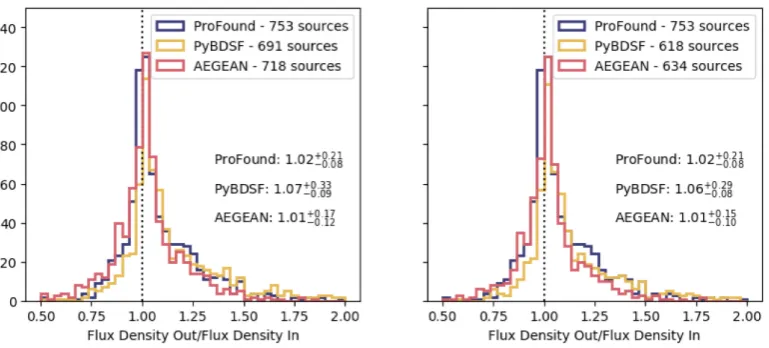
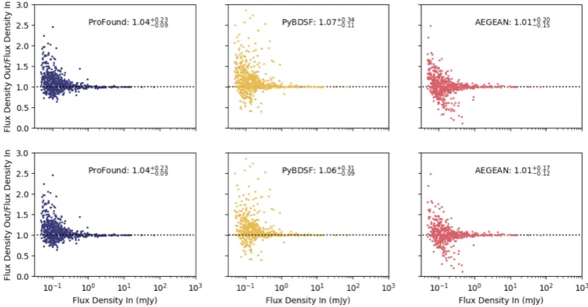
The results from this simulation are shown in Figs9 and10.
Again all the source extraction software exhibit peaks around
∼1 for the ratio of the recovered to the injected flux density.
However there is typically an excess at high ratios. Whereas
AEGEAN has a median ratio of∼1.01, PYBDSF and PROFOUND
both appear to find an excess of emission compared to what is
in injected, ∼1.04 for PROFOUND and ∼1.06 for PYBDSF and
therefore may be slightly over predicting the flux density of a source. All three however, give peaks around the same value and have similar scatter to one another, demonstrating that they all perform similarly well for the simple uniform elliptical source morphology.
[image:11.595.93.501.306.528.2]Figure 9. Comparisons of the injected flux densities compared to the fluxes recovered using PROFOUND(blue), PYBDSF (yellow) and AEGEAN (red). This is for the simulations in which elliptical sources are injected into the image. Shown is a histogram of the recovered to input flux densities. The median value of the output to input flux density ratio and its uncertainties derived from the 16th and 84th percentiles are shown in both figures and the number of sources detected from each software is shown in the legend. The left-hand plots use the source extraction parameters described in Section 3.2 whilst the right-hand plots use the default parameters for PYBDSF and AEGEAN.
Figure 10. Comparisons of the injected flux densities compared to the fluxes recovered using PROFOUND(blue, left panel), PYBDSF (yellow, middle panel) and AEGEAN (red, right panel). This is for the simulations in which elliptical sources are injected into the image. Shown is the ratio of recovered to input fluxes as a function of input flux density. The median value of the output to input flux density ratio and its uncertainties derived from the 16th and 84th percentiles are shown in both figures and the number of sources detected from each software is shown in the legend. The upper row of plots use the source extraction parameters described in Section 3.2 whilst the lower row of plots use the default parameters for PYBDSF and AEGEAN.
5.3 Extended sources – from the image
Next, we focus on sources that consist of complicated morphologies.
To do this, we use the large objects found in the PROFOUNDblind
detection of the VLA image and re-inject these in the residual image. These large sources were typically the most complicated
morphologies. We define ‘large’ here as those that had anR50
≥ 3.5, whereR50 is defined in PROFOUND as the approximate
elliptical semimajor axis containing 50 per cent of the flux. This
corresponds to 81 objects within the central∼1 deg2.
To avoid any issues of this becoming a circular argument where
we extract radio emission from PROFOUNDand then re-extract using
PROFOUND to see how well PROFOUND behaves, we artificially
multiply the models of the sources by a random factor. This factor is generated as a random number between 0.01–1.0 but selected so that it is sampled uniformly in logarithmic space. By doing this and by injecting these sources at random positions, we change the effect of the noise. This is likely to make it more difficult to extract with
PROFOUND. For these simulations we add in each object 5 times to
[image:12.595.84.503.317.536.2]Radio source extraction with P
ROF
OUND3983
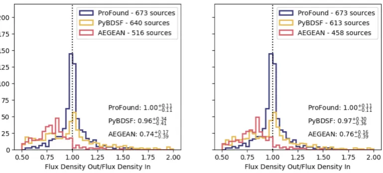
Figure 11. Comparisons of the injected flux densities compared to the fluxes recovered using PROFOUND(blue), PYBDSF (withatrous do, yellow) and AEGEAN (red). This is for the simulations in which extended objects extracted from the original image using PROFOUNDare injected. Shown is a histogram of the recovered to input flux densities. The median value of the output to input flux density ratio and its uncertainties derived from the 16th and 84th percentiles are shown in both figures and the number of sources detected from each software is shown in the legend. The left-hand plots use the source extraction parameters described in Section 3.2 whilst the right-hand plots use the default parameters for PYBDSF and AEGEAN.
Figure 12. Comparisons of the injected flux densities compared to the fluxes recovered using PROFOUND(blue, left panel), PYBDSF (yellow, middle panel) and AEGEAN (red, right panel). This is for the simulations in which extended objects extracted from the original image using PROFOUNDare injected. Shown is the ratio of recovered to input fluxes as a function of input flux density. The median value of the output to input flux density ratio and its uncertainties derived from the 16th and 84th percentiles are shown in both figures and the number of sources detected from each software is shown in the legend. The upper row of plots use the source extraction parameters described in Section 3.2 whilst the lower row of plots use the default parameters for PYBDSF and AEGEAN.
were used due to the extended nature of these sources and so in order to avoid sources being merged together, their numbers were reduced.
Due to the lower recovery rate of sources and the complicated nature of the sources themselves, the simulations were repeated
5 times and the combined results of these are shown in Figs11
and12. From Figs11 and12, it is evident that PROFOUNDdoes
an excellent job recovering the flux densities of sources compared
to PYBDSF and AEGEAN. In these simulations, PROFOUNDgives
a flux density ratio of 1.00+0.11
−0.11 whereas AEGEAN has a ratio of
0.76+−00..1639, when the default parameters are used. This shows that
AEGEAN is underestimating the flux density of objects that have
complicated and large morphologies. As using the atrous do
mode will be important in this simulation, the results from PYBDSF
using this is shown in Figs11and12. The results from PYBDSF are
centred on a value of 1 (0.97+−00..3036), suggesting PYBDSF is able to
accurately recover the emission from extended sources. However the
scatter is much larger than for PROFOUND, with values of∼0.3−4
for the scatter with PYBDSF compared to∼0.1 for PROFOUND. This
suggests both PYBDSF and AEGEAN may struggle to consistently
model the entire emission of the source or that it may be harder to combine multiple components together in a consistent way (as
[image:13.595.86.506.308.528.2]Figure 13. Comparisons of the injected flux densities compared to the fluxes recovered using PROFOUND(blue), PYBDSF (withoutatrous do, yellow) and AEGEAN (red). This is for the simulations in which multicomponent elliptical sources are injected into the image. Shown is a histogram of the recovered to input flux densities. The median value of the output to input flux density ratio and its uncertainties derived from the 16th and 84th percentiles are shown in both figures and the number of sources detected from each software is shown in the legend. The left-hand plots use the source extraction parameters described in Section 3.2 whilst the right-hand plots use the default parameters for PYBDSF and AEGEAN.
it is done here purely within a fixed angular separation here). This suggests that in previous continuum surveys the flux densities of complicated sources may have been under/over estimated. This has implications for the descriptions of radio source populations, such as
source counts, luminosity functions and spectral indices. PROFOUND
also has a much smaller scatter in the flux density ratios that it
calculates compared to PYBDSF and PROFOUND. This emphasises
PROFOUND’s ability to accurately extract the flux densities of those
source with complex morphologies.
5.4 Extended sources – multicomponent elliptical sources
For our final simulations, we again investigate how well extended sources can be recovered, this time using the component catalogues
of S3(Wilman et al.2008). In Section 5.2, we injected elliptical
components from S3convolved with the beam, however these were
single individual components. In this simulation, we instead inject
all components of one source into the residual image. In S3,
Star-Forming Galaxies (SFGs) are described as one component objects, where as FRI and FRII-type Active Galactic Nuclei (AGN) are formed of multiple components of e.g. a core, jets and hotspots. These are all described by elliptical components, which we convolve with the beam individually, before summing together to form the source. We inject 500 of these multicomponent objects. Again, fewer sources are injected due to the extended nature of these sources and we also do not inject single-component sources, i.e. SFGs, as these are the same as from the simulations in Section 5.2. The results of our recovered to injected flux density ratios can
be seen in Figs13and 14. This suggests that all three detection
mechanisms seem to do a good job in re-extracting the flux density
of these sources, with all having a flux density ratio of∼1. This
is a value of 1.01−+00..1405 for PROFOUND, 1.02+
0.24
−0.07 for PYBDSF and
0.99+0.07
−0.44 for AEGEAN, again using the default parameters. This
suggests that all three of these source extractors are able to sensibly model objects that have smooth, double-lobed morphologies.
How-ever, again the scatter in PROFOUNDis typically much smaller than
for PYBDSF or AEGEAN, suggesting PROFOUNDcan more often
recover the flux densities of these sources accurately.
Overall, these simulations suggest that PYBDSF and AEGEAN
perform well for most source types however are less suitable to extract the emission of radio sources that have complex
mor-phologies. PROFOUND however has shown that it is capable of
successfully determining the flux densities for a variety of source morphologies, including the Gaussians and sources with compli-cated morphologies that are typically observed in radio continuum observations.
5.5 Completeness and reliability
We also show, in Fig.15, the completeness and reliability
distri-bution as a function of flux density for each of the simulations discussed in Sections 5.1–5.4. Completeness is defined as the fraction of sources that are input into the simulated images for which the source is found in the output catalogue. Reliability on the other hand is the fraction of sources obtained in the output catalogue of the simulation that have a counterpart in the input catalogue.
To determine completeness and reliability, the input and output catalogues were matched within an angular radius. For both of these,
only sources that had RA/Dec values within the central deg2of the
image (i.e. the overlap region with CFHTLS D1) were considered, this was to ensure that any noise detection from around the region of higher rms around outside of the image were not included, as sources were only detected in this central region. The angular radius used here is given as 3 arcsec (as used earlier in Sections 5.1–5.4)
for the Gaussian and Elliptical simulations (Figs 15(a) and (b),
as these are compact, smooth sources. For the extended objects,
described in Sections 5.3 and 5.4 (Figs15(c) and (d)), due to the
larger nature of these objects, and the multicomponent nature of the objects described in Section 5.4, a larger angular radius is used. This
is taken to be 15 arcsec (or∼3×the beam size). As well as showing
Completeness (left-hand panels) and Reliability (central panels),
we also present the product of the two: Completeness×Reliability
(right-hand panels), this is to indicate a compromise between the two.
Fig.15 shows that PROFOUND has comparable Completeness,
Radio source extraction with P
ROF
OUND3985
Figure 14. Comparisons of the injected flux densities compared to the fluxes recovered using PROFOUND(blue, left panel), PYBDSF (yellow, middle panel) and AEGEAN (red, right panel). This is for the simulations in which multicomponent elliptical sources are injected into the image. Shown is the ratio of recovered to input fluxes as a function of input flux density. The median value of the output to input flux density ratio and its uncertainties derived from the 16th and 84th percentiles are shown in both figures and the number of sources detected from each software is shown in the legend. The upper row of plots use the source extraction parameters described in Section 3.2 whilst the lower row of plots use the default parameters for PYBDSF and AEGEAN.
AEGEAN, demonstrating that it is comparable to other known radio source extractors, despite its different approach to extracting
sources. For Fig. 15, the parameters determined in Section 3.2
are used for AEGEAN and PYBDSF to minimize the effect of
different false detection levels on reliability. For extended sources
(Fig.15(c)), however PROFOUNDproduces slightly larger values of
completeness×reliability compared to PYBDSF and AEGEAN for
extended sources over∼0.2−5 mJy. This suggests that PROFOUND
is successfully modelling this complicated emission. However, these will all be influenced by the matching radius used as well as whether sources have been merged together into a single source or not, or whether it has been split into multiple components, both of which can put the positions of the new sources at large distances from the original location of the source(s). Therefore, this should be taken into account when considering the plots shown in
Fig.15.
6 3 C S O U R C E S
As the benefits of PROFOUND arise in its ability to model and
calculate flux densities of extended sources, we make one final comparison to compare how well the different software perform on known extended sources. To do this we use images of five 3C sources that were described in Section 2.2.2. To compare the fitting of the sources, we both compared the visual fitting as well as investigating the residuals of the image, as in Section 4.
A comparison of the visual models of these sources from the
different source extractors can be seen in Fig.16 (top panel for
each source). The image is shown on the left-hand side of each
sub-figure panel with the models from PROFOUND, PYBDSF and
AEGEAN also shown. We also include the segmentation map from
PROFOUND of the source. Each colour in these plots represents
a different source as defined by PROFOUND, after the grouping
mentioned in Section 3.1. As with the other comparison images,
the images from PYBDSF and AEGEAN here are those using the
default extraction parameters. The bottom panel for each object shows the corresponding residual image.
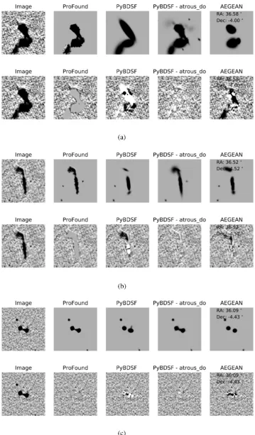
Fig.16illustrates how PROFOUNDis able to trace the shape of the
source and so model its radio emission. In the cases shown here, both
PYBDSF (withoutatrous do) and AEGEAN do not adequately
model the emission seen in the image. Visually, they are unable to constrain the complicated morphology of these sources. For components that are missing, many of these are bright, compared
to the sky level, and so it is not aσ level discrepancy that causes
components to be missing or not well modelled. Withatrous do,
however, PYBDSF is able to better model the emission of these
sources. The residual images in Fig.16also show how PROFOUND
is tracing the shape well but also includes some noise in the model
of the source. For PYBDSF and AEGEAN the 3C images appear
to have been over-fit in areas, which can leave negative residuals around the source.
To quantify how well PROFOUNDis able to recover all the radio
emission for these sources, again we investigate the residual image. If a source extractor has truly recovered the emission from the object, only noise should remain which should appear as a Gaussian distribution centred around zero. The results of this can be seen in
Fig.17. Also shown is a model for Gaussian noise as a grey dashed
line, this again used to highlight what typical Gaussian noise in the image should look like. This was modelled by fitting the histogram
of the negative residuals from PROFOUND, fit for both amplitude
andσ.
From Fig.17it can be seen that the residuals from PROFOUND
are consistently well modelled as a Gaussian. This suggests it is successfully extracting the full fluxes of these sources. Although occasionally there are small excesses at high and low-flux densities
per beam (e.g. Fig.17(e)). There is also a peak in the histogram
around a flux density per beam of 0 mJy/beam. This excess is
again due to the smooth sky model that PROFOUNDuses and so
Figure 15. Comparisons of the completeness (left-hand plots), reliability (central plots) and completeness×reliability (right-hand plots) using PROFOUND
(blue), PYBDSF (yellow), and AEGEAN (red) for the four simulations performed. The completeness and reliability for the simulations with: (a) Gaussian sources; (b) elliptical sources; (c) extended objects extracted from the original image with PROFOUNDand (d) multicomponent elliptical sources are shown. These are shown using the detection parameters of PYBDSF and AEGEAN determined in Section 3.2 but withatrous doused for PYBDSF in (c). small noise fluctuations may be included as part of the source. This
was not as obvious in the residuals from Section 4 due to both the large number of pixels as well as the small covering factor of sources in the image. In these images of 3C sources, however, the source is a large fraction of the image and so this excess at
0 mJy/beam is obvious. For PYBDSF and AEGEAN on the other
hand, there are very clear excesses in the flux density per beam of the residuals at both high and low values. As the definition of residual is the image-model, at high-flux densities per beam an excess
represents where a source model has under predicted the flux density per beam whereas an excess at negative flux densities pre beam suggests that the Gaussian components have over-predicted the flux
density per beam needed. With atrous doon for PYBDSF, it
Radio source extraction with P
ROF
OUND3987
Figure 16. Comparison of the model (top row) and residual (bottom row) images from PROFOUND(panel 2), PYBDSF (panel 4 withoutatrous doand panel 5 withatrous do=True) and AEGEAN (panel 6) of five 3C sources (whose images are shown in panel 1). These are shown for the sources: 3C16 (a), 3C19 (b), 3C28 (c), 3C42 (d) and 3C47 (e). The segmentation images from PROFOUNDare shown in panel 3. Here, PYBDSF and AEGEAN use the default parameters as described in Section 3, and used in Hopkins et al. (2015). Shown are the entirety of the images downloaded fromhttp://www.jb.man.ac.uk/atlas/ (Leahy, Bridle, Strom1996).
Figure 17. Comparison of the residuals derived from the models from PROFOUND(blue), PYBDSF (yellow) and AEGEAN (red) of five 3C sources (whose images are shown in the left-hand panel). Also shown is a Gaussian (fit for both amplitude andσ) used to give a modelled estimate of the noise. An estimate ofσ(in Jy), which is related to the noise is given in the legend in the top right-hand corner. These are shown for the sources: 3C16 (a), 3C19 (b), 3C28 (c), 3C42 (d) and 3C47 (e) as seen in Fig.16(where the entire image for which these residuals are calculated over are shown). This is shown when the default parameters of PYBDSF and AEGEAN are used to generate the source models.
This work therefore highlights how PROFOUND is capable of
tracing and modelling the emission from sources with known ex-tended jet emission. It also highlights how using assumed Gaussian components may end up over-fitting such emission.
7 D I S C U S S I O N S A N D C O N C L U S I O N S
In this paper, we have shown the potential of using PROFOUNDto
detect and model the emission of sources from radio continuum
images. PROFOUNDwas developed with the aim of optical and IR
surveys, where noise is uncorrelated however we have shown in this paper that despite the heavily correlated noise in radio continuum imaging, pixel based extraction software are able to work well in
this regime. Using PROFOUNDdoes not assume a morphology, the
flux of resolved sources can be better traced and as components of a certain morphology are not used, regions outside the source can not be over fit.
PROFOUNDhas been tested in this paper through simulations of
varying morphologies and consistently calculates accurate flux den-sities of sources. These morphologies were created using Gaussians, elliptical discs convolved with the beam and complex extended
sources. Both PYBDSF and AEGEAN also succeeded well in
recovering the flux densities of single objects (i.e. the Gaussian and elliptical sources) or smooth double lobed objects. However, they struggled in comparison to recover the flux densities of extended sources which have complex morphologies.
By considering the residuals that remain in the images once
Radio source extraction with P
ROF
OUND3989
successfully model the flux of sources. This was especially evident when five 3C sources were investigated where there was an excess of negative residuals for the other software. This is related to the fact that Gaussian components are not always appropriate to model these complex sources and may over fit the extended emission whilst also missing flux in other regions.
For current and future surveys there are both benefits to using source extractors that fit Gaussian components as well as pixel based source extraction. Fitting Gaussian components is especially useful for calibration purposes in building up sky models (an application we are not considering in this study). As well as this, for telescopes
such as the MWA (Tingay et al.2013) as well as in single-dish
observations with e.g. Arecibo and the Green Bank Telescope (GBT), the resolution of these telescopes is constrained to arcminute resolution, and so images are likely to consist of unresolved sources which have a known shape given by the synthesised beam of the telescope. In this case where all the emission is typically unresolved, fitting Gaussian sources (of the beam shape) may seem as an appropriate method. Other radio facilities however such as the VLA,
MeerKAT (Jonas & MeerKAT Team2016), ASKAP (Norris et al.
2011) and LOFAR (van Haarlem et al.2013) resolve more structure
to the AGN and SFGs they observe. In these cases PROFOUND
models the full complexity of these sources, as shown in Figs3
and 16. For surveys from these facilities PROFOUND may have
an advantage by better modelling these complexities as well as combining multiple components of the same source together. This obviously will not work in cases where e.g. there are two lobed jets separated by a large separation, however these would not be merged together by any standard source finding algorithm. By
also showing that PROFOUNDsuccessfully detects smooth Gaussian
emission we suggest that PROFOUND is capable of accounting
for and characterising the multitude of sources observed in radio surveys.
We therefore feel that PROFOUNDmay be a beneficial source
ex-traction software for both current as well as the future radio surveys that we expect to complete at higher angular resolutions and greater
depths. Not only this, but as PROFOUNDis designed to be used
within a multiwavelength framework. This can therefore be used to generate consistent flux extraction of sources across the
electromag-netic spectrum. This is by using segments defined by PROFOUNDat
one wavelength to calculate fluxes at another. This will be useful for not only obtaining consistently extracted fluxes at different radio frequencies but can also be important in making use of observations across the electromagnetic spectrum. This is advantageous in the era of multiwavelength astronomy. It also has the potential to use the ancillary information to make sub-threshold detections of radio sources, which we will discuss further in future work.
AC K N OW L E D G E M E N T S
We thank the Referee for their useful comments with this work. CLH would like to acknowledge the support given from the Science and Technology Facilities Council (STFC) for their support to the first author through an STFC studentship (ST/N504233/1). CLH is also grateful to STFC for their support and funding for a Long Term Attachment (LTA), which made this work possible. This work was also supported by the Oxford Hintze Centre for Astrophysical Surveys, which is funded through generous support
from the Hintze Family Charitable Foundation and the award of the STFC consolidated grant (ST/N000919/1).
R E F E R E N C E S
Bell E. F., 2003,ApJ, 586, 794
Bertin E., Arnouts S., 1996,A&AS, 117, 393 Callingham J. R. et al., 2016,MNRAS, 462, 290 Condon J. J. et al., 2012,ApJ, 758, 23
Cuillandre J.-C. J., et al., 2012, Introduction to the CFHT Legacy Survey Final Release (CFHTLS T0007), in Observatory Operations: Strategies, Processes and Systems IV, Vol. 8448, Society of Photo-Optical Instrumentation Engineers (SPIE) Conference Series, p. 84480M Davies L. J. M. et al., 2017,MNRAS, 466, 2312
Davies L. J. M. et al., 2018,MNRAS, 480, 768
Edge D. O., Shakeshaft J. R., McAdam W. B., Baldwin J. E., Archer S., 1959, MNRAS, 68, 37
Fanaroff B. L., Riley J. M., 1974,MNRAS, 167, 31P
Feretti L., Gioia I. M., Giovannini G., Gregorini L., Padrielli L., 1984, A&A, 139, 50
Galvin T. J. et al., 2018,MNRAS, 474, 779
Garn T., Green D. A., Riley J. M., Alexander P., 2009,MNRAS, 397, 1101 Hale C. L. et al., 2019,A&A, 622, A4
Hancock P. J., Murphy T., Gaensler B. M., Hopkins A., Curran J. R., 2012,
MNRAS, 422, 1812
Hancock P. J., Trott C. M., Hurley-Walker N., 2018,PASA, 35, e011 Helfand D. J., White R. L., Becker R. H., 2015,ApJ, 801, 26 Hopkins A. M. et al., 2015,PASA, 32, e037
Hudelot P. et al., 2012, VizieR Online Data Catalog. p. II/317 Hurley-Walker N. et al., 2017,MNRAS, 464, 1146
Jarvis M. et al., 2016, in Proceedings of MeerKAT Science: On the Pathway to the SKA. 25-27 May. p. 6, preprint (arXiv:1709.01901)
Jarvis M. J. et al., 2013,MNRAS, 428, 1281 Johnston S. et al., 2008,Exp. Astron., 22, 151
Jonas J., MeerKAT Team, 2016, in Proceedings of MeerKAT Science: On the Pathway to the SKA. 25-27 May, 2016 Stellenbosch, South Africa (MeerKAT2016). p. 1 Online athttps://pos.sissa.it/cgi-bin/reader/conf .cgi?confid = 277, id.1.
Laing R. A., Riley J. M., Longair M. S., 1983,MNRAS, 204, 151 Leahy J. P., 1996,Vistas Astron., 40, 173
Leahy J. P., Bridle A. H., Strom R. G., 1996,http://www.jb.man.ac.uk/atlas/ Leahy J. P., Perley R. A., 1991,AJ, 102, 537
Mauch T., Sadler E. M., 2007,MNRAS, 375, 931 Mauduit J.-C. et al., 2012, PASP, 124, 714
Mohan N., Rafferty D., 2015, PyBDSF: Python Blob Detection and Source Finder, Astrophysics Source Code Library.(ascl:1502.007)
Norris R. P. et al., 2011, PASA, 28, 215
Pierre M. et al., 2004,J. Cosmol. Astropart. Phys., 9, 011 Pracy M. B. et al., 2016,MNRAS, 460, 2
Prandoni I., 2018, in Jeli´c V., van der Hulst T., eds, IAU Symposium Vol. 333, Peering towards Cosmic Dawn. p. 175, preprint (arXiv:1806.10886) Prescott M. et al., 2016,MNRAS, 457, 730
Robotham A. S. G., Davies L. J. M., Driver S. P., Koushan S., Taranu D. S., Casura S., Liske J., 2018,MNRAS, 476, 3137
Shimwell T. W. et al., 2017,A&A, 598, A104 Smolˇci´c V. et al., 2017,A&A, 602, A1 Smolˇci´c V. et al., 2017,A&A, 602, A6
Tasse C., R¨ottgering H. J. A., Best P. N., Cohen A. S., Pierre M., Wilman R., 2007,A&A, 471, 1105
Tingay S. J. et al., 2013,PASA, 30, e007 van Haarlem M. P. et al., 2013,A&A, 556, A2 Wayth R. B. et al., 2015,PASA, 32, e025 Wilman R. J. et al., 2008,MNRAS, 388, 1335
This paper has been typeset from a TEX/LATEX file prepared by the author.