e-ISSN: 2278-067X, p-ISSN: 2278-800X, www.ijerd.com
Volume 10, Issue 4 (April 2014), PP.36-42
Test Pattern Generation By Using Accumulator
S.Ramya
1, S.Karthikeyan
21
Department of ECE, M.Tech VLSI Design, Sathyabama University, Tamilnadu, India.
2Department of ECE, Ass.Proffessor, Sathyabama University, Tamilnadu, India.
Abstract:- Weighted pseudorandom built-in self test (BIST) schemes have been utilized in order to drive down the number of vectors to achieve complete fault coverage in BIST applications. Weighted sets comprising three weights, namely 0, 1, and 0.5 have been successfully utilized so far for test pattern generation, since they result in both low testing time and low consumed power. In this paper an accumulator-based 3-weight test pattern generation scheme is presented; the proposed scheme generates set of patterns with weights 0, 0.5, and 1. Since accumulators are commonly found in current VLSI chips, this scheme can be efficiently utilized to drive down the hardware of BIST pattern generation, as well. Comparisons with previously presented schemes indicate that the proposed scheme compares favorably with respect to the required hardware.
Keywords:- Built-in-self-test(BIST),test per clock, VLSI testing, Weighted test pattern generation.
I.
INTRODUCTION
Pseudorandom BIST generators have been widely utilized to test integrated circuits and systems. The arsenal of pseudorandom generators includes, among others, linear feedback shift registers (LFSRs), cellular automata, and accumulators driven by a constant value. For circuits with hard-to-detect faults, a large number of random patterns have to be generated before high fault coverage is achieved. Therefore, weighted pseudorandom techniques have been proposed where inputs are biased by changing the probability of a “0” or a “1” on a given input from 0.5 (for pure pseudorandom tests) to some other value. In order to minimize the hardware implementation cost, other schemes based on multiple weight assignments utilized weights 0, 1, and 0.5. This approach boils down to keeping some outputs of the generator steady (to either 0 or 1) and letting the remaining outputs change values (pseudo-) randomly (weight 0.5). This approach, apart from reducing the hardware overhead has beneficial effect on the consumed power, since some of the circuit under test (CUT) inputs (those having weight 0 or 1) remain steady during the specific test session [1].
BIST is a design-for-testability technique that places the testing functions physically with the circuit under test (CUT). The basic BIST architecture requires the addition of three hardware blocks to a digital circuit: a test pattern generator, a response analyzer, and a test controller. The test pattern generator generates the test patterns for the CUT. Examples of pattern generators are a ROM with stored patterns, a counter, and a LFSR. A typical response analyzer is a comparator with stored responses or an LFSR used as a signature analyzer. It compacts and analyzes the test responses to determine correctness of the CUT. A test control block is necessary to activate the test and analyze the responses. However, in general, several test-related functions can be executed through a test controller circuit.
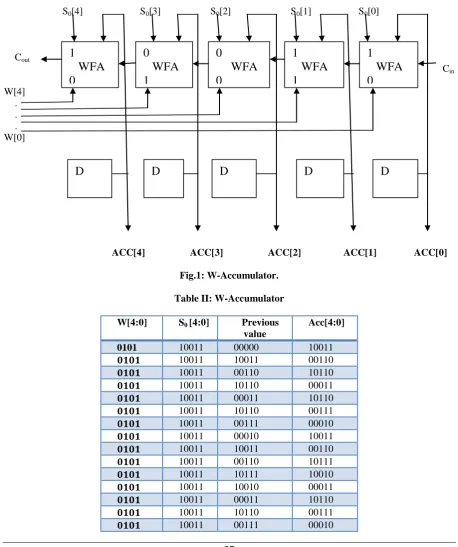
Following the conversation of the previous Section, the W-accumulator operates as follows: for those inputs i for which W[i]=0, the values of A[i] and cout[i] are presented. The table 2.1 shows below.
Table I: Operation of W-accumulator
W[i] New value of ACC[i] Cout[i]
0 Se[i]ACC[i]Cin[i] ACC.Se[i]+ACC[i].Cin[i]+
Se[i]. Cin[i]
1 Se[i] Cin[i]
bladder mounted inside a shell. The shell acts as a pressure container for both the gas (in the bladder) and the hydraulic fluid. The bladder provides the barrier between the inert gas and the fluid to prevent intermixing. The piston style uses a cylinder with a floating piston. The cylinder serves as the pressure container for both the gas and fluid while the piston provides the barrier between the gas and the oil to prevent intermixing. Note that oxygen is never used as it can be explosive when mixed with oil under high pressure. One of the most important considerations in applying accumulators is calculating the correct pre-charge pressure for the type of accumulator being used, the work to be done and system operating parameters. Pre-charge pressure is generally 80 - 90% of the minimum system working pressure to allow a small amount of fluid to remain in the accumulator. This prevents the bladder, diaphragm or piston from striking the opposite end of the pressure vessel, getting fouled up in discharge valuing or blocking fluid passages. Too high or too low of a pre-charge pressure can cause accumulator damage or failure. Conversely, a properly designed and maintained accumulator should operate trouble-free for years
.
S0[4] S0[3] S0[2] S0[1] S0[0]
Cout Cin W[4] . . . W[0]
ACC[4] ACC[3] ACC[2] ACC[1] ACC[0]
Fig.1: W-Accumulator.
Table II: W-Accumulator
W[4:0] S0 [4:0] Previous value
Acc[4:0]
0101 10011 00000 10011
0101 10011 10011 00110
0101 10011 00110 10110
0101 10011 10110 00011
0101 10011 00011 10110
0101 10011 10110 00111
0101 10011 00111 00010
0101 10011 00010 10011
0101 10011 10011 00110
0101 10011 00110 10111
0101 10011 10111 10010
0101 10011 10010 00011
0101 10011 00011 10110
0101 10011 10110 00111
0101 10011 00111 00010
1
WFA
0
0
WFA
1
0
WFA
0
1
WFA
1
1
WFA
0
0101 10011 00010 10011
0101 10011 10011 00110
0101 10011 00110 10111
0101 10011 10111 10010
0101 10011 10010 00011
0101 10011 00011 00010
0101 10011 00010 10011
0101 10011 10011 00110
0101 10011 00110 10111
0101 10011 10111 10010
0101 10011 10010 00010
0101 10011 00010 10110
0101 10011 10110 00111
0101 10011 00111 00110
0101 10011 00110 00111
0101 10011 00111 00010
The W-Accumulator provides the repetition in the output and get 2-weight pattern generation Area Overhead: Additional active area due to test controller, pattern generator, response evaluator and testing of BIST hardware. Performance overhead: Extra path delays are added due to BIST. Yield loss increases due to increased chip area. Design effort and time increases due to design BIST. It can be utilized only in the case of adder of accumulator is a Ripple carry adder. It require redesigning accumulator; this modification apart from being costly. It increase delay, since its affects the normal operating speed of the adder.
II.
PROPOSED
ACCUMULATOR
CELL
A new weighted random pattern design for testability is described where the shift register latches distributed throughout the chip are modified so that they can generate biased pseudo-random patterns upon demand. A two-bit code is transmitted to each weighted random pattern shift register latches to determine its specific weight. The weighted random pattern test is then divided into groups, where each group is activated with a different set of weights. The weights are dynamically adjusted during the course of the test to "go after" the remaining untested faults.
Cin
Set[n-1:0] Reset[n-1:0]
A[n-1:0] A[n-2:0] . ... .. ... ... A[0]
Fig.2: Block diagram of proposed ACCUMULATOR CELL
Register B
Adder
Register A
Session
A. Internal structural of Accumulator cell :
Session Counter: The Session counter in order to alter among the different weight sessions. The session counter consists of n bits, where n is the number of test sessions of the weighted test set. All schemes require the application of the session counter, required to alter among the different weight sessions.
Logic Module: Provides the Set[n-1:0] and Reset[n-1:0] signals that drive the S and R inputs of the Register A and Register B inputs. Note that the signals that drive the S inputs of the flip-flops of Register A, also drive the R inputs of the flip-flops of Register B and vice versa. 3-weight pattern generation scheme proposed. The scan chain is driven by the output of a linear feedback shift register (LFSR). Logic is inserted between the scan chain and the CUT inputs to fix the outputs to the required weight (0, 0.5, or 1). In order to implement the scheme an s can structure is assumed. Furthermore, an LFSR required to feed the pseudorandom inputs to the scan inputs is implemented (where n is the number of scan cells), as well as a scan counter, common to all scan schemes.
Accumulator: Weighted pattern generation scheme is based on the accumulator cell presented. Which consists of a Full Adder (FA) cell and a D-type flip-flop with asynchronous set and reset inputs whose output is also driven to one of the full adder inputs. We assume, without loss of generality, that the set and reset are active high signals. BIST is a design-for-testability technique that places the testing functions physically with the circuit under test (CUT). The basic BIST architecture requires the addition of three hardware blocks to a digital circuit: a test pattern generator, a response analyzer, and a test controller. The test pattern generator generates the test patterns for the CUT. Examples of pattern generators are a ROM with stored patterns, a counter, and a linear feedback shift register (LFSR). A typical response analyzer is a comparator with stored responses or an LFSR used as a signature analyzer. It compacts and analyzes the test responses to determine correctness of the CUT. A test control block is necessary to activate the test and analyze the responses. However, in general, several test-related functions can be executed through a test controller circuit. The main object of the weighted pattern generation is an accumulator cell. To implement the accumulator in the proposed weighted pattern generation scheme is based on presented in Fig3
Fig: 3: Internal structure Accumulator Cell
Which consists of a Full Adder (FA) cell and a D-type flip-flop with asynchronous set and reset inputs whose output is also driven to one of the full adder inputs. In the above figure, we assume that the set and reset are active high signals and at the same time the set and reset are used to without loss of generality. And at the time, the respective cell of another register B[i] is also occurred. For this accumulator cell, one out of three configurations can be utilized, as shown in Fig3. The configuration that drives the CUT inputs. When A[i] =1 is required, So the set[i]=1 and reset[i]=0 and hence A[i]=1 and B[i]=0. Then the output is equal to 1,and Cin is equal to Cout. i.e., the Cin is transferred to the Cout. And similarly, When A[i] =0 is required, So the set[i]=0 and reset[i]=1 and hence A[i]=0 and B[i]=1. Then the output is equal to 0, and here Cin is equal to Cout. i.e., the Cin is transferred to the Cout. When A[i] = “-” is required, so the set[i] =0 and reset[i] =0. The D input of the flip-flop of register B is driven by either 1 or 0, depending on the value that will be added to the accumulator inputs in order to generate satisfactorily random patterns to the inputs of the CUT.
III.
C880
BENCHMARK
CIRCUIT
To check the performance of the bench mark circuit c880. The Bench mark circuit Fig 4.consists of 60 inputs, 26 outputs, and 383 gates. It’s an 8-bit ALU with high level model. The core of this 8-bit ALU is an 8-bit 74283-style adder. To analyze the C880 we have to modify our proposed test pattern architecture. Because C880 consist of 60 inputs but our proposed testing hardware provides of demo test pattern only.
Fig 4:C880 Benchmark Circuit
PERFORMANCE COMPARISONS
Performance comparisons mainly discuss about Weight pattern generation and Repetition. Simulating the output in Model Sim 6.4c.
A.
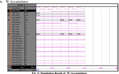
W-Accumulator
Fig .5: Simulation Result of W-Accumulator
The Fig4 contains clock, set, reset. set 0, reset 1. Put cin=1.input A-00101,input W-01110 and cin=1
B. Top Module With Weight-Accumulator cell
Fig.6: Simulation Result of Top Module with Weight
The Fig. 6 describes about 3-Weight pattern generation .The input is 00 and get the output is 0.5,The input is 11 and get the output is 0.5,The input is 10 and get he output is 1,The input is 01 and get the output is 0.Finillay,provide the output no repetition occurred.
C. Bench Mark with Top Module Weight
Fig.7: Bench mark Circuit with Weight.
The Fig 7. Explain about the output of Top Module with Weight is given to the input of c880 Benchmark Circuit and get he output is no repetition occurred
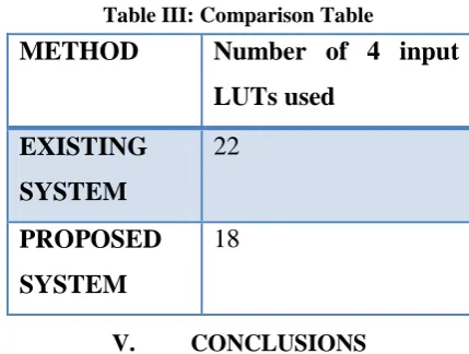
D. Comparison Table:
The table 1 shows the existing system and proposed system of Accumulator
Table III: Comparison Table
V.
CONCLUSIONS
Test pattern generation by using Accumulator weight (0, 0.5, and 1) test-per-clock generation scheme, which can be utilized to efficiently generate weighted patterns without altering the structure of the adder. Comparisons with a previously proposed accumulator-based 3-weight pattern generation technique and it indicates that the hardware overhead of the proposed scheme is lower, while at the same time no redesign of the accumulator is imposed, thus resulting in reduction in test application time. Comparisons with scan based schemes show that the proposed schemes results in lower hardware overhead. Finally, comparisons with the accumulator- based scheme proposed and reveal that the proposed scheme results in significant decrease in hardware overhead.
REFERENCES
[1]. P. Bardell, W. McAnney, and J. Savir, Built-In Test For VLSI: Pseudorandom Techniques. New York: Wiley, 1987
[2]. P. Hortensius, R. McLeod, W. Pries, M. Miller, and H. Card, “Cellular automata-based pseudorandom generators for built-in self test,” IEEE Trans. Comput.-Aided Des. Integr. Circuits Syst., vol. 8, no. 8, pp. 842–859, Aug. 1989.
[3]. A. Stroele, “A self test approach using accumulators as test pattern generators,” in Proc. Int. Symp. Circuits Syst., 1995, pp. 2120–2123.
[4]. H. J. Wunderlich, “Multiple distributions for biased random test patterns,” in Proc. IEEE Int. Test Conf., 1988, pp. 236–244.
[5]. I. Pomeranz and S. M. Reddy, “3 weight pseudo-random test generation based on a deterministic test set for combinational and sequential circuits,” IEEE Trans. Comput.-Aided Des. Integr. Circuits Syst., vol.12, no. 7, pp. 1050–1058, Jul. 1993.
[6]. K. Radecka, J. Rajski, and J. Tyszer, “Arithmetic built-in self-test for DSP cores,” IEEE Trans. Comput.-Aided Des. Integr. Circuits Syst., vol. 16, no. 11, pp. 1358–1369, Nov. 1997.
[7]. J. Rajski and J. Tyszer, Arithmetic Built-In Self Test For Embedded Systems. Upper Saddle River, NJ: Prentice Hall PTR, 1998.
[8]. S. Wang, “Low hardware overhead scan based 3-weight weighted random BIST,” in Proc. IEEE Int. Test Conf., 2001, pp. 868–877.
[9]. S. Zhang, S. C. Seth, and B. B. Bhattacharya, “Efficient test compaction for pseudo-random testing,” in Proc. 14th Asian Test Symp., 2005, pp. 337–342.
[10]. J. Savir, “Distributed generation of weighted random patterns,” IEEE Trans. Comput., vol. 48, no. 12, pp. 1364–1368, Dec. 1999.
[11]. I. Voyiatzis, D. Gizopoulos, and A. Paschalis, “Accumulator-based weighted pattern generation,” presented at the IEEE Int. Line Test Symp., Saint Raphael, French Riviera, France, Jul. 2005.
![Table I: Operation of W-accumulator Cout[i] ACC.Se[i]+ACC[i].Cin[i]+](https://thumb-us.123doks.com/thumbv2/123dok_us/1386532.1649557/1.595.77.514.642.695/table-operation-accumulator-cout-acc-se-acc-cin.webp)