Article
1
Low Order Harmonics Control in Stair Case
2
Waveform by a Novel Estimation based Technique
3
Salman Ahmad1, Atif Iqbal2, Imtiaz Ashraf1, Sanjeevikumar Padmanaban3,*, Mohammed Meraj2
4
1 Department of Electrical Engineering, Aligarh Muslim University, Aligarh, India;
5
[email protected], [email protected]
6
2 Department of Electrical Engineering, Qatar University, Qatar; [email protected], [email protected]
7
3 Department of Energy Technology, Aalborg University, 6700 Esbjerg, Denmark; [email protected]
8
* Correspondence: [email protected]; Tel.: +45-71-682-084
9
10
Abstract: Few switching transitions in high power and medium voltage application of Power
11
converters are desirable. The selective harmonics elimination (SHE) pulse width modulation offers
12
a better quality waveform with lower switching transitions and hence lower switching losses. The
13
SHE is a pre-programmed modulation technique where certain amounts of lower order harmonics
14
are removed and fundamental voltage is controlled. After Fourier analysis of output waveform, a
15
set of nonlinear transcendental equations is obtained which exhibits, multiple, unique or no
16
solution in different range of modulation index (MI). In this paper, an iterative method based on
17
the Jacobian estimate is proposed to solve a highly non-linear set of SHE equations. The proposed
18
technique is easy in implementation and can solve a large number of such equations as
19
computation of the Jacobian matrix in the subsequent iteration is estimated from the previous
20
values. Moreover, the proposed method also removes the singularity problem, especially for large
21
SHE equations. High accuracy in the initial guess is also not essential for this method and can
22
converge to the solution with any random initial guess. The computational and simulation results
23
are given to validate the concept. The hardware result is provided to confirm the computational
24
and simulation results.
25
Keywords: Staircase Waveform; Harmonics Control; Field Programming gate array (FPGA);
26
Estimation; Iterative technique, VHDL
27
28
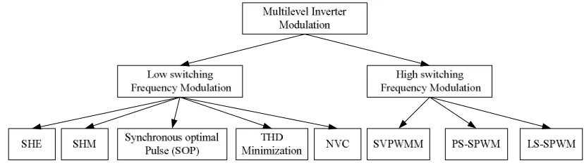
1. Introduction
29
Multilevel voltage source/current source converters have been widely studied and researched
30
for a variety of applications which includes induction machine drives, renewable energy integration
31
in the grid, active rectifiers, pumps, fans, rolling mills, marine propulsion, HVDC transmission,
32
railway traction etc. [1–7]. Various research groups mainly focused on its topology, modulation,
33
and control algorithm. The important topologies include Neutral point clamped (NPC), cascaded H
34
bridge (CHB) and Flying capacitor (FC) and various hybrid topologies such as active neutral point
35
clamped (ANPC), H bridge neutral point clamped (HNPC) etc. The performance characteristics of
36
multilevel converters are highly dependent on the choice of modulation techniques adopted for
37
their operation. The broad classification of important modulation techniques is high switching
38
frequency pulse width modulation techniques and low switching frequency techniques [8]. The
39
high switching frequency techniques include sine pulse width modulation (SPWM) based phase
40
shifted (PS-PWM), level shifted (LS-PWM) and space vector pulse width modulation (SVPWM) [3].
41
The low switching frequency modulation techniques are classified as optimum PWM, selective
42
harmonics elimination (SHE) PWM, nearest vector control (NVC) PWM and selective harmonics
43
mitigation (SHM) PWM [9-10]. In the high switching frequency PWM techniques the power
44
switches are operated at several kHz and yield good quality waveforms whereas lower switching
45
frequency PWM techniques operate power electronics switches at few hundreds of Hertz [11–12].A
46
detailed classification modulation method for the multi-level inverter is shown in Fig.1 [3], [8], [10].
47
48
49
Figure 1.Pulse width modulation techniques for multilevel inverter
50
51
In medium voltage and high power converters, low switching frequency PWM techniques are
52
preferred as the switching losses are one of the most important criteria for its operation. Among
53
various low switching frequency PWM techniques, SHE PWM is widely investigated and
54
researched for various industrial applications [11–14], [15–20]. It is a pre-programmed PWM
55
technique which selectively eliminates particular harmonics along with control of the fundamental
56
voltage [21–26]. The Fourier series analysis of the output waveform is carried out and set of
57
nonlinear transcendental equations are obtained which eliminates pre-specified order of harmonics
58
along with control of the fundamental frequency voltage component. After offline computation for
59
switching angles is done, these values for the different modulation index are stored in a look-up
60
table [27]. Depending upon the modulation index a particular set of switching angles applies to the
61
power electronics switches in order to obtain the desired waveform at the output. Some literature
62
also tried to implement it in real times by adopting techniques such as artificial neural network
63
(ANN), model predictive control, and criteria based control techniques [28–31]. Real-time
64
implementation is useful, especially in unequal dc voltages such as application in solar photovoltaic
65
as the size of the lookup table is huge and will consume a lot of memory of the processor board. A
66
criteria based modulation (CBM) strategy is also proposed which selects the optimum switching
67
angles from a given objective function while considering all the practical constraints such as
68
minimum ON and OFF times from the set of solution stored in the lookup table[32].
69
The main challenge to utilize SHE modulation methodology lies in solving the switching angles
70
from the set of nonlinear transcendental equations which exhibits unique, multiple or no solution
71
for different values of modulation indices (MI). The most commonly used methods to solve these
72
equations proposed in the literature are the numerical techniques based conventional methods,
73
Algebraic methods and various optimization methods such evolutionary and swarm-based
74
metaheuristic methods. The numerical based methods mainly include Newton Raphson method,
75
sequential homotopy and analytical methods [23],[33–34]. Numerical methods are very simple to
76
use, but an accurate guess along with computation of derivates makes these methods difficult to use
77
and sometimes may fail to give all the solution to the problem. Moreover, they are useful to solve
78
only few switching angles as calculation of first derivatives become very difficult as size increases.
79
Algebraic methods such as Walsh function, resultant theory, and Groebner method are proposed in
80
[35-37]. In the algebraic method, the trigonometric equations are first converted into polynomial
81
equations by multiple angle formulas and then are solved by a simple Gaussian elimination method
82
of solving linear equations. Although these methods can give all the possible solutions, but as the
number of switching angle increases more than four, the method becomes very complex and
84
time-consuming. The optimization based methods such as genetic algorithm (GA)[38], particle
85
swarm optimization (PSO)[39], Bee algorithm[40], ant colony optimization (ACO)[41], memetic
86
algorithm [42] and differential evolution (DE) algorithm[27], tries to minimize an objective function
87
to obtain optimal switching angles. Although the optimization method is less dependent on initial
88
guess, but is very slow convergent, doesn’t give very accurate results and takes longer time in its
89
computation. Moreover, it requires an experience and expert knowledge of its computational
90
algorithm. A detailed analysis of various optimizations based SHE methods is given in [10], [43].
91
In this paper, a novel iterative method with Jacobian estimates is proposed. The proposed
92
method is fast convergent and easier in its implementation. Moreover, it gives all the possible
93
solutions with any random, initial guess which overcomes the problem of numerical techniques.
94
Also, the proposed method is capable of evaluating a large number of switching angles (levels) with
95
efficient convergence. The computational results are presented for various switching angles starting
96
from five switching angles (11-levels) to fifteen switching angles (31-level). The harmonics profile at
97
some particular modulation index and %THD is also given. The simulation results of phase and line
98
voltages are obtained using Simulink to verify the computational results. A prototype is also built
99
in the laboratory to validate the computational and simulation results.
100
2. Problem Formulation: Mathematical Analysis
101
Figure 2a shows a typical configuration of single phase cascaded H-cell inverter having n cells
102
with n- separate dc sources. The IGBT switches operated in the fundamental switching frequency.
103
The output voltage of the cascaded H Bridge is given by the summation of voltages from different
104
H-cells. To analyze the output voltage waveform from the inverter, Fourier series expansion is used.
105
The general Fourier series expansion can be expressed as (1);
106
) sin( )
cos( 2
) (
1
0
a a n b n
v n
n
n
(1)
Where Fourier Coefficients are defined as (2) and (3)
107
0 )
cos( ) ( 1
n , d n v
an
(2)
1 )
cos( ) ( 1
n , d n v
bn
(3)Considering quarter wave symmetry in the output waveform shown in Fig. 2b, we will have
108
a0=0 and an=0 and the generalized Fourier coefficient for the multilevel stepped waveform is given by
109
(4).
110
en n , for ev
odd n ) , for (nα
nπ V b
s
N
k
k dc
n
0
cos 4
1 (4)
Where bn is the amplitude of the nth harmonics and Ns is the number of switching angles in a
111
quarter’s period. By having Ns switching angles in a quarterly period Ns-1 harmonics can be
112
eliminated along with control of the fundamental frequency component, defined by modulation
113
index,
115
(a)
116
s N 1 2
0 /2 3/2 2
SHE
v
SHE v
117
(b)
118
Figure2. Generalized multilevel inverter structure(a) Circuit topology(b) Output stepped waveform
119
from one leg
120
121
m (0<m<1). The set of non-linear transcendental equations is given by (5) and (6) while eliminating
122
lower order harmonics along with varying m in linear range.
123
s
N
k
k dc
s V N m
1 cos 4
(5)
s
N
k
k n
1 cos
0 (6)
Wheren
3,5,72Ns1
in the case of single phase cascaded H-bridge inverter and for 3 phase124
case n
5,7,11,133Ns2; Nsodd
or n
5,7,11,133Ns1;Nseven
.The amplitude of the125
fundamental frequency component for both the cases is given by (7).
126
s dc
SHE V mN
v ,14
(7)
Where vSHE,1
is defined as the fundamental frequency voltage magnitude. In the case of five
127
switching angles (11-level), the set of selective harmonic elimination equations for 3-phase
128
multilevel inverter considering four low order non-triplen harmonics for elimination is given in (8)
) 13 cos( ) 13 cos( ) 13 cos( ) 13 cos( ) 13 cos( ) 11 cos( ) 11 cos( ) 11 cos( ) 11 cos( ) 11 cos( ) 7 cos( ) 7 cos( ) 7 cos( ) 7 cos( ) 7 cos( ) 5 cos( ) 5 cos( ) 5 cos( ) 5 cos( ) 5 cos( 5 ) cos( ) cos( ) cos( ) cos( ) cos( 5 4 3 2 1 5 4 3 2 1 5 4 3 2 1 5 4 3 2 1 5 4 3 2 1 m G (8)
131
132
The generalized non-linear transcendental equation given in (5) and (6) for various cases is
133
solved in the next section by using the proposed Jacobian estimation based iterative technique.
134
3. Switching Angles Computation by Fast Novel approach
135
The selective harmonics elimination represents a set of n non-linear simultaneous
136
transcendental equations, having equality and non-equality constraints with maximum and
137
minimum bounds on the design variables, which in generalized and vector form is represented by
138
(9), and (10).
139
140
( ) 0
( ) 0, 1, 2, ( ) 0, 1, 2, , 1, 2,
k
t
i i i
Solve G subject to
g k M
h t T
L U i N
(9)
1, 2, 3,
0,
0,1,
N
Ns k t
i i
i s
R g h
L U i N
(10)
Where n
R
and n n
R R
G(): is a n×1 function matrix. This problem may have many, unique or
141
no solution. The inequality along with upper and lower bounds on the switching angles is given by
142
(11).
143
2
0
1
2
3
Ns
(11)In the Newton Raphson method, the main challenge is in the computation of the Jacobian matrix in
144
the subsequent iterations. This problem further aggravated in solving the nonlinear equation for
145
large variables. In addition, the Jacobian Matrix becomes a singular matrix when the difference in
146
the solution vectors in the consecutive iterations becomes small. These challenges can be solved be
147
adopting a technique which needs Jacobian matrix computation only at the start of the algorithm
148
and then Jacobian matrix in the subsequent iterations is estimated using previous iteration values.
149
At the start of the algorithm, the initial values of different functions are obtained using (12) to (14).
150
) ( () ) ( 0 0 G J (12)
( )
( ) )(i i
G
J 0 1
(13)
) ( ) ( )
(i i i
1 (14)The value of Jacobian Matrix in (12) alternatively can be estimated by using the values of function
151
vectors evaluated in the previous iterations. If moving from ithiteration to (i+1)th iteration the
152
can be approximated to be J(i). Therefore, the rank one update given in (12) can be used for the
154
Jacobian matrix in (i+1)th iteration.
155
i T i i iY X J
J(1) () () () (15)
In (15), X(i) and Y(i) are vectors whose values depend upon solution vectors and function matrix in the
156
two consecutive iterations i.e. on α(i), α(i+1), G(i), and G(i+1). The Jacobian estimate formula can be
157
derived by considering the Jacobian J(i) which produces Δα(i), as given in (16)-(18).
158
159
) ( ) ( )
(i i i
G
J (16)
160
) ( ) ( )
(i i i
1 (17)
161
) ( ) 1 ( )
(i i i
G G
G
(18)
To accurately estimate the Jacobian matrix in the (i+1)th iteration, i.e. J(i+1) the following two
162
conditions should be imposed on the designed vector.
163
1. For a vector z, if
()
0 i Tz
, i.e. in the perpendicular direction of (i)
, a new Jacobian
164
estimate (i1)
J maintains the same function vectorG. BothJ(i) and (i1)
J are related to vector
165
z given in (19).
166
z
J
z
J
(i)
(i1) (19)2. The prediction for (i1)
J (i)
is same in linear expansion as for (i)
G
, i.e.
167
) ( ) 1 ( ) ( ) 1
(i i i i
J G
G
(20) or
168
) ( ) ( ) 1
(k i i
G
J
(21)
Also for the normal vector
z
to
(i), the following relations are obtained given in (22)-(25);169
) ( ) ( ) 1
(k i i
G
J (22)
170
z Y X z J z
J(i1) (i) (i)[ (i)]T
(23)
171
z J z
J(i 1) (i)
(24)
172
0 ] [ ()
) (
z Y
X i i T (25)
We can choose
y
(i)
(i1)because
(i)is perpendicular toz
. After substituting in (15) and173
post-multiplying by
(i)the relationship is modified as given in (26).174
) ( ) ( ) ( ) ( ) ( ) ( ) 1 (
]
[
i T ii i i i i
X
J
Using (21) and substituting in (15), will yield (27) and (28).
175
) ( ) ( ) ( ) ( ) ( ) (]
[
i T ii i i i
X
J
G
(27)]
]
[[
]
[
) ( ) ( ) ( ) ( ) ( ) ( i T i i i ii
G
J
X
(28)Therefore, the Jacobian estimate for the next iteration can be found by (29).
176
]
]
[[
]
][
[
) ( ) ( ) ( ) ( ) ( ) ( ) ( ) 1 ( i T i T i i i i ii
G
J
J
J
(29)Thus, on further simplification the approximate Jacobian estimate is given by (30).
177
() () ()
( 1) ) 1 ( ) ( ) ( ) ( i i i i i i i i
G J
G G
J
G
(30)
]
]
[
[
]
]
[[
1
( 1) ()) ( ) ( ) ( ) 1
( i i T
i T i i i
G
J
J
(31)The solution by iterative methods is required to generate an approximation of the set of
178
simultaneous equations. The approximation of the solution is normally generated using the iteration
179
sequence of vectors under considered space vector given in (32).
180
, , , , i G ii 1) [ ()] ; 0123 ( (32)
In the proposed method, the convergence criteria for the required solution are defined as in (33)-(34).
181
1 ) 1 (
max i
G (33) 2 ) 1 ( ) ( ) 1 ( min
i i i (34)Where ε1and ε2represent the accuracy required in the solution. The quality or effectiveness of the
182
modulation techniques is expressed in terms of non-desirable components in the output relative to
183
a pure sinusoidal (desired) component. For three phase system, it is expressed as given in (35).
184
185
1001 % 2 49 ,... 3 , 2 , 1 1 6 1
n n V V THD (35)Where V1 represents the peak value of the fundamental component of line-to-line voltage and Vn
186
represents that of nth harmonics component. A systematic implementation process of the proposed
187
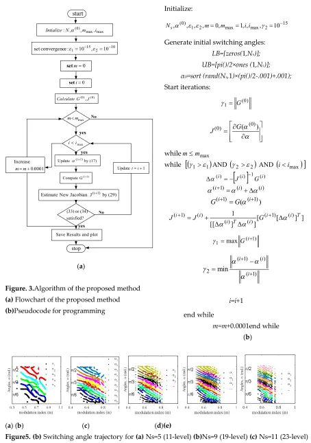
method for solving the non-linear transcendental SHE equations is given in Fig. 3.
188
This section may be divided by subheadings. It should provide a concise and precise
189
description of the experimental results, their interpretation as well as the experimental conclusions
190
that can be drawn.
191
4. Computational and Simulation Results
192
For computation of switching angles Intel core i7-7500U CPU, 16 GB RAM is used and a
193
program is written using MATLAB 2016 software. In various cases of a number of switching angles
194
(Ns=3, 5…15) the solution trajectories of switching angles as a function of modulation index are
195
obtained and shown in fig.(4)-(6). The minimum and maximum modulation index is set to 0 and 1,
respectively, and varied in the step of Δm=0.0001. Also, various important graphs are plotted such as
197
a maximum error in the Non-linear system of equations given in (10), total harmonic distortion as a
198
function of modulation, the number of iterations required to reach the convergence point set in the
199
problem, the convergence rate for a particular modulation index and the harmonics profile at
200
particular modulation index. Selective computational results are shown in Fig. 4 and Fig.5.
201
Table (1) shows the three solutions obtained by this method for Ns=5, m=0.5467. The choice of
202
best solution is application dependent and one can choose based on minimum THD, minimum,
203
differences in consecutive switching angles, and transition from one modulation point to another.
204
Table 1 Solutions for Ns=5, m=0.5467
205
Switching angles (rad.)
1. 10.605,20.776,30.951,41.43;51.368 2. 10.092,20.611,30.771,41.371;51.567
3. 10.3503,2 0.689,30.989,4 1.111;51.539
Figure 4(b) shows the percentage total harmonic distortion in the whole solution as a function
206
of modulation index computed using (35). The convergence of the maximum function in (8) is shown
207
in Fig. 4c. Figure 4d shows the convergence of the whole solutions up to a specified accuracy (~10-15)
208
for various modulation indexes. Most of the solution converges within 30 iterations which is
209
evident from Fig. 4d.Likewise, computations are done for a large number of switching cases. Figure
210
5(a)-(d) shows solution trajectories for Ns=3, Ns=9, Ns=11 and Ns=13, respectively. These trajectories
211
confirm that there are multiple solutions, unique solution and no solution in the linear range of
212
modulation index. In case of Ns=15, at m(0.5517,0.7637)and there are three solutions at m=0.58 and
213
is given in Table (2). For Ns=15 the %THD lies in the range (1.69,2.78)for the entire solution obtained
214
by the proposed method. Also, the trajectories in Fig.5, shows a similarity in the switching patterns,
215
therefore, for higher switching angles the solution can be predicted using these trajectories and
216
advanced mathematical techniques. A simulation model has been developed in MATLAB/Simulink
217
to verify the computational results obtained from the proposed method. The simulation for a large
218
number of switching angle cases have been carried out and selected results for Ns=5; and Ns=15for
219
number of switching angles are shown in Fig. 6.Figure 6 (a) and (b) shows the solution trajectories of
220
Ns=5 and Ns=15respectively. The spectrum phase and line voltages along with a harmonic spectrum
221
of line voltages for m=0.84 and m=0.76is shown in Fig. 6c and 6d for Ns=5and Ns=15, respectively. The
222
harmonics profile confirms that lower order harmonics considered for elimination are absent from
223
the output waveforms. The next significant harmonics are of the order 17th, 19th…etc. for 11-level and
224
47th, 51st… etc. for 31-level case.
225
226
(a) (b) (c) (d)
227
Figure4.Computational Results for Ns=7 (15-level inverter) (a) Switching angles (rad.) as a function
228
of modulation index (b) Percentage THD as function of modulation index (c) Convergence steps for
229
m=0.53 (d) Maximum iterations to reach the accuracy (~10-15)
230
231
A
n
g
le
s,
(
ra
d
.)
0.3 0.4 0.5 0.6 0.7 0.8 0.9
modulation index (m)
5 9
%
T
H
max max ) 0 ( , , ,
:N m i
Intialize 0 m set 0 i set max m m max i i ) 0 ( ) 0 ( ,J
G Calculate
(17) by Update(i1)
(29) by J Jacobian New
Estimate (i1)
1) (i G Compute satisfied? (34) or (33) plot and Results Save start stop 1 Updateii
0001 . 0 Increase m m yes yes yes No No 10 2 15 1 10 , 10 :
e convergenc
set
(a)
Figure. 3.Algorithm of the proposed method
(a) Flowchart of the proposed method (b)Pseudocode for programming
Initialize: 15 2 max max 2 1 ) 0 ( 10 , , , 1 , 0 , , ,
, m m ii
Ns
Generate initial switching angles:
LB=[zeros(1,Ns)]; UB=[pi()/2×ones (1,Ns)]; α0=sort (rand(Ns,1)×(pi()/2-.001)+.001);
Start iterations:
) 0 ( 1 G
) ( (0) )
0
( G
J
whilemmmax
while
11
AND
2 2
AND
iimax
() 1 () )(i J i G i
) ( ) ( ) 1
(i i i
) ( ( 1) ) 1 ( i i G G ] ] [ [ ] ] [[
1 ( 1) ()
) ( ) ( ) ( ) 1
( i i T
i T i i i G J J ) 1 ( 1maxG i
) 1 ( ) ( ) 1 (
2 min
i i i i=i+1 end while m=m+0.0001end while (b)
232
(a) (b) (c) (d)(e)
233
Figure5. (b) Switching angle trajectory for (a) Ns=5 (11-level) (b)Ns=9 (19-level) (c) Ns=11 (23-level)
234
237
(a) (b)
238
Figure6. Simulation results(a) Line voltage and harmonics profile at m=0.84 for Ns=5(b) Line
239
voltage harmonics profile at m=0.76 for Ns=15
240
Table 2 Solutions for Ns=15, m=0.58
241
Switching angles (rad.)
536 . 1 , 442 . 1 ; 355 . 1 ; 203 . 1 , 139 . 1 , 066 . 1 , 013 . 1 ; 938 . 0 ; 898 . 0 , 788 . 0 ; 697 . 0 ; 679 . 0 , 587 . 0 , 570 . 0 , 232 . 0 15 14 13 12 11 10 9 8 7 6 5 4 3 2 1 53 . 1 , 437 . 1 ; 352 . 1 ; 27 . 1 , 135 . 1 , 065 . 1 , 01 . 1 ; 940 . 0 ; 819 . 0 , 782 . 0 ; 702 . 0 ; 674 . 0 , 589 . 0 , 567 . 0 , 154 . 0 15 14 13 12 11 10 9 8 7 6 5 4 3 2 1 531 . 1 , 351 . 1 ; 271 . 1 ; 203 . 1 , 129 . 1 , 072 . 1 , 999 . 0 ; 952 . 0 ; 877 . 0 , 836 . 0 ; 765 . 0 ; 719 . 0 , 601 . 0 , 556 . 0 , 386 . 0 15 14 13 12 11 10 9 8 7 6 5 4 3 2 1
5. Hardware setup and experimental results
242
A prototype is developed in the laboratory to practically validate the correctness of the
243
switching angles computed by the proposed method. The prototype developed and the control
244
algorithm for implementation of SHE PWM for various cases is shown in Fig. 7. The Semikron
245
SKM100GB12T4 is used to build the H-bridge inverter. The control code is developed and
246
implemented using Matlab/Xilinx blocks interface with FPGA VIRTEX- 5XC5VLX50T.Since the
247
FPGA board used in the experimental work offers a clock of 50 MHz so, 20 ns time resolution of the
248
gate signal is achieved. The dead time is not required as the two switches in the same leg never
249
operate simultaneously. It also ensures better resolution of the output waveform and avoids any
250
pulse dropping, in case the difference in consecutive switching angles are very small. The switching
251
frequency of the IGBT switches of the inverter is kept at line frequency (50 Hz). The PWM gating
252
pulses have given to gate drivers ADuM3220. For recording the harmonics profile in the output
253
voltage waveform, a Fluke 43B single-phase power quality analyzer has been used. The harmonic
254
content only up to 49th has been recorded since the contribution higher order harmonics in the THD
255
is not significant.
1
23
Ns1 G
2
G
s
N G4
g1 g2 g4Ns258
5
A
0
4A
3
A
2
A
1
A
1
A
4
A
3
A
2
A
5
A
1
1
2
2
3
4
5
3
4
5
259
(a) (b)
260
261
262
Figure.7Hardware setup and Experimental procedure(a) Hardware schematic (b) Gating pulse
264
generation(c) Actual prototype developed in the laboratory(d) Logics to generate gating pulses
265
266
For 7-level and 11-level cascaded H-bridge case, the experiments have been carried out using the
267
developed prototype. The experimental data are given in Table (3). The sine magnitude of the
268
switching angles computed in the previous section is stored in the lookup table. This stored value as
269
per modulation index fed switching instants and compared with a sinusoidal waveform to produce
270
gating pulses as shown in Fig. 7b and 7d. The selected results for m=0.747 and m=0.836 have been
271
shown for 7-level and 11- level cases in Fig.8. The voltage spectrum shows that the targeted
272
harmonics for elimination i.e. 5th 7th and 5th 7th, 11th, 13th are absent in the output voltage waveform
273
respectively.
274
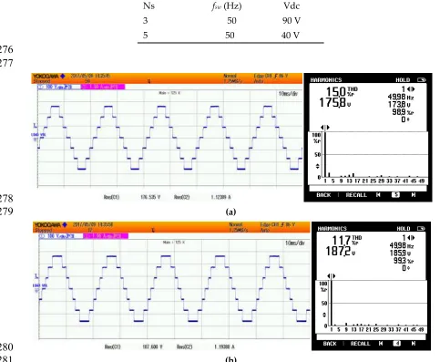
Table 3 Experimental parameters
275
Ns fsw (Hz) Vdc
3 50 90 V
5 50 40 V
276
277
278
(a)
279
280
282
(c)
283
284
(d)
285
Figure.8Hardware results(a) Phase voltages at m=0.505 for Ns=3(b) Phase voltages at m=0.550 for
286
Ns=3(c) Phase voltages at m=0.747 for Ns=5(d) Phase voltages at m=0.836 for Ns=5
287
5. Conclusion
288
In this paper, a novel Jacobian estimation based iterative method is proposed for the
289
computation of switching angles in the selective harmonics elimination problem. Since the
290
computation of the Jacobian is avoided in each iteration, the speed of computation is fast. Moreover,
291
the singularity problem associated with the inverse of the Jacobian matrix evaluation is also avoided.
292
It makes the proposed method more suitable for computation of a large number of switching angles
293
in SHE PWM and hence higher stepped waveform. Moreover, the fast computational speed allows
294
taking a very small step increment for modulation index and it ensures multiple solutions at various
295
modulation indexes. The non-triplen lower order odd harmonics are considered for elimination
296
from the output waveform. The proposed technique has been successfully implemented for
297
switching angles from three to fifteen or from seven levels stepped waveform to 31 levels stepped
298
waveforms. In the different range of modulation indices, different numbers of solutions are found.
299
The %THD for all the cases and solutions is also computed and reported. Selective computational
300
and simulation results are given for 11-level and 31-level. A prototype is also developed and
301
practical results are provided for 7-level and 11-level to validate the computational results.
302
303
Author Contributions: All authors contributed equally to the final presented research article.
304
305
Funding: This paper was made possible by NPRP grant # X-033-2-007 from the Qatar National
306
Research Fund (a member of Qatar Foundation). The statement made herein are solely the
307
responsibility of the authors.
Conflicts of Interest: The authors declare no conflict of interest.
309
References
310
1. Rodríguez, J., Lai, J., and Peng, F., ‘Multilevel Inverters : A Survey of Topologies, Controls, and
311
Applications’, 2002, 49, (4), pp. 724–738.
312
2. Malinowski, M., Gopakumar, K., Rodriguez, J., Perez, A., ‘A survey on cascaded multilevel
313
inverters’,IEEE Trans. Ind. Electron., 2010, 57, (7), pp. 2197–2206.
314
3. Kouro, S., Malinowski, M., Gopakumar, K., et al., ‘Recent Advances and Industrial Applications
315
of Multilevel Converters’, IEEE Trans. Ind. Electron., 2010, 57, (8), pp. 2553–2580.
316
4. Steczek, M., Chudzik, P., and Szelag, A., ‘Combination of SHE and SHM - PWM techniques for
317
VSI DC-link current harmonics control in railway applications’,2017, IEEE Trans. Ind. Electron.,
318
46, (6), pp. 2155–2170.
319
5. S. S. Lee, B. Chu, N. Rumzi, N. Idris, and, “Switched-Battery Boost-Multilevel Inverter with GA
320
Optimized SHEPWM for Standalone Application” ,2015, IEEE Trans. Ind. Electron., 46, (8).
321
6. Imarazene, K., Chekireb, H., Berkouk, E.M.: ‘Selective harmonics elimination PWM with
322
self-balancing DC-link in photovoltaic 7-level inverter’Turkish J. Electr. Eng. Comput. Sci., 2016,
323
24, (5), pp. 3999–4014.
324
7. Zabaleta, M., Burguete, E., Madariaga, D., et al., ‘LCL grid filter design of a multimegawatt
325
medium-voltage converter for offshore wind turbine using SHEPWM modulation’IEEE Trans.
326
Power Electron., 2016, 31, (3), pp. 1993–2001.
327
8. B. Wu, High-power converters and ac drives. Wiley-IEEE press, 2006.
328
9. Lin, L., Lin, Y., He, Z., et al., ‘Improved Nearest-Level Modulation for a Modular Multilevel
329
Converter With a Lower Submodule Number’IEEE Trans. Power Electron., 2016, 31, (8), pp.
330
5369–5377.
331
10. Dahidah, M., Konstantinou, G., and Agelidis, V., ‘A Review of Multilevel Selective Harmonic
332
Elimination PWM: Formulations, Solving Algorithms, Implementation and Applications’, IEEE
333
Trans. Power Electron., 2015, 30, (8), pp. 4091–4106.
334
11. Yang, K., Zhang, Q., Zhang, J., et al., ‘Unified selective harmonic elimination for multilevel
335
converters’, IEEE Trans. Power Electron., 2017, 32, (2), pp. 1579–1590
336
12. J. G. H Abu-Rub, A Iqbal, High performance control of AC drives with MATLAB/Simulink models.
337
Wiley , 2012.
338
13. Konstantinou, G., Pou, J., Capella, G.J., Song, K., Ceballos, S., Agelidis, V.G.: ‘Interleaved
339
Operation of Three-Level Neutral Point Clamped Converter Legs and Reduction of Circulating
340
Currents under SHE-PWM’IEEE Trans. Ind. Electron., 2016, 63, (6), pp. 3323–3332.
341
14. Luiz, A.S.A., Filho, B.J.C.: ‘A new design of selective harmonic elimination for adjustable speed
342
operation of AC motors in mining industry’. IEEE Int. Conf. Applied Power Electronics Conf.
343
Exposition (APEC), March 2017, pp. 607–614.
344
15. Flourentzou, N., and Agelidis, V., ‘Multimodule HVDC system using SHE-PWM with DC
345
capacitor voltage equalization,IEEE Trans. Power Deliv., 2012, 27, (1), pp. 79–86.
346
16. S. R. Pulikanti, G. Konstantinou, and V. G. Agelidis, “DC-link voltage ripple compensation for
347
multilevel active-neutral-point- clamped converters operated with SHE-PWM,” IEEE Trans.
348
Power Deliv.,2012, 27, (4), pp. 2176–2184.
349
17. Mei, J., Xiao, B., Shen, K., et al., ‘Modular multilevel inverter with new modulation method and
350
its application to photovoltaic grid-connected generator’, 2013IEEE Trans. Power Electron., 28,
(11), pp. 5063–5073.
352
18. Filho, F., Tolbert,Cao, L., and Ozpineci, B., ‘Real-time selective harmonic minimization for
353
multilevel inverters connected to solar panels using artificial neural network angle generation’,
354
2011 IEEE Trans. Ind. Appl., 47, (5), pp. 2117–2124.
355
19. Y. Gopal , D. Birla and M. Lalwani.”Selected Harmonic Elimination for Cascaded Multilevel
356
Inverter Based on Photovoltaic with Fuzzy Logic Control Maximum Power Point Tracking
357
Technique”, MDPI-Technologies2018, 6, 1-17.
358
20. Konstantinou, G., Ciobotaru, M., and Agelidis, V., ‘Selective harmonic elimination pulse-width
359
modulation of modular multilevel converters’, IET Power Electron., 2013, 6, (1), pp. 96–107.
360
21. Nibouche, M., Bouchhida, O., and Makhlouf, B., ‘Design, analysis and implementation of
361
real-time harmonics elimination: a generalised approach’, IET Power Electron., 2014, 7, (9), pp.
362
2424–2436.
363
22. Enjeti, P., Ziogas, P., and Lindsay, J., ‘Programmed PWM tech- niques to eliminate harmonics: a
364
critical evaluation’, IEEE Trans. Ind. Appl., 1990, 26 , (2) pp. 302-316.
365
23. Haw, L., Dahidah, M., and Almurib, H., ‘SHE-PWM cascaded multilevel inverter with
366
adjustable DC voltage levels control for STATCOM applications’, IEEE Trans. Power Electron.,
367
2014, 29, (12), pp. 6433–6444.
368
24. Mohammed Al-Hitmi, Salman Ahmad, Atif Iqbal, SanjeevikumarPadmanaban, “Selective
369
Harmonic Elimination in a Wide Modulation Range Using Modified Newton – Raphson
370
Multilevel Inverter,” MDPI, energies, vol. 11, no. 458, pp. 1–16, 2018.
371
25. Lou, H., Mao, C., Wang, D., Lu, J., and Wang, L., 'Fundamental Modulation Strategy with
372
Selective Harmonic Elimination for Multilevel Inverters', IET Power Electronics, 2014, 7, (8), pp.
373
2173-2181.
374
26. Konstantinou,Dahidah, M., and Agelidis, V.,‘Solution trajectories for selective harmonic
375
elimination pulse-width modulation for seven-level waveforms: analysis and implementation’,
376
2012, IET Power Electron., 5, (1), pp. 22-30.
377
27. Salam, Z., Majed, A., and Amjad, A., ‘Design and implementation of 15-level cascaded
378
multi-level voltage source inverter with harmonics elimination pulse-width modulation using
379
differential evolution method’,IET Power Electron., 2015, 8, (9), pp. 1740–1748.
380
28. Filho. F., Maia, H., Mateus, T., et al., ‘Adaptive selective harmonic minimization based on
381
ANNs for cascade multilevel inverters with varying DC sources’IEEE Trans. Ind. Electron., 2013,
382
60, (5), pp. 1955–1962.
383
29. Aguilera, R., Lezana, P., Konstantinou, G., et al., ‘Closed-loop SHE-PWM technique for power
384
converters through Model Predictive Control’ 2015, in Industrial Electronics Society, IECON-
385
41st Annual Conference of the IEEE, Yokohama, Japan, pp. 005 261–005 266.
386
30. Ahmed, M., Sheir, A., Orabi, M. ‘Real Time Solution and Implementation of Selective Harmonic
387
Elimination of Seven-Level Multilevel Inverter’IEEE J. Emerg. Sel. Top. Power Electron., 2017,.5,
388
(4), pp. 1700-1709.
389
31. Balasubramonian, M. and Rajamani, V., 'Design and Real-Time Implementation of SHEPWM in
390
Single- Phase Inverter Using Generalized Hopfield Neural Network', IEEE Transactions on
391
Industrial Electronics, 2014, 61, (11), pp. 6327-6336.
392
32. Dagan, K., and Rabinovici, R., ‘Criteria-based modulation for multilevel inverters’, IEEE Trans.
393
33. Kato. T, “Sequential Homotopy-Based Computation of Multiple Solutions for Selected
395
Harmonic Elimination in PWM Inverters,” IEEE Trans. Cicuits Syst. Fundam. theory Appl., 1999,
396
46, (5), pp. 586–593.
397
34. Buccella, C., Cecati, C., Cimoroni, M., and Razi, K., ‘Analytical method for pattern generation in
398
five-level cascaded H-bridge inverter using selective harmonic elimination’,IEEE Trans. Ind.
399
Electron., 2014, 61, (11), pp. 5811–5819.
400
35. Swift. F and Kamberis, A., ‘A New Walsh Domain Technique of Harmonic Elimination and
401
Voltage Control in Pulse Width Modulated Inverters’,IEEE Trans. Power Electron., 1993, 8, (2),
402
pp. 170–185.
403
36. Chiasson, J., Tolbert, L., McKenzie, K., and Du, Z., ‘Control of a multilevel converter using
404
resultant theory’,IEEE Trans. Control Syst. Technol., 2003,11, (3), pp. 345–354.
405
37. K. Yang, Z. Yuan, R. Yuan, W. Yu, J. Yuan, and J. Wang, “A Groebner Bases Theory Based
406
Method for Selective Harmonic Elimination,” IEEE Trans. Power Electron., 2015, 30, (12), pp.
407
6581–6592.
408
38. Ozpineci, B., Tolbert, L., and Chiasson, J.,’Harmonic Optimization of Multilevel Converters
409
Using Genetic Algorithms’, IEEE Power Electronics letters, 2005, 3, (3), pp. 92–95.
410
39. Ray, R., Chatterjee, D., and Goswami, S., ‘Harmonics elimination in a multilevel inverter using
411
the particle swarm optimisation technique’, IET Power Electron., 2009, 2,(6), p. 646.
412
40. Kavousi, A., Vahidi, B., Salehi, R.,et al., ‘Application of the bee algorithm for selective harmonic
413
elimination strategy in multilevel inverters’, IEEE Trans. Power Electron., 2012, 27, (4), pp.
414
1689–1696.
415
41. Sundareswaran, K., Jayant, K., and Shanavas, T., ‘Inverter Harmonic Elimination Through a
416
Colony of Continuously Exploring Ants’ IEEE Trans. Ind. Electron., 2007, 54, (5), pp. 2558–2565.
417
42. Heidari, Y., Jabbarvaziri, F., Niknam Kumle, A., et al., ‘Application of memetic algorithm for
418
selective harmonic elimination in multi-level inverters’, IET Power Electron., 2015, 8, (9), pp.
419
1733–1739.
420
43. Kundu, S., Burman, A.D., Giri, S.K., Mukherjee, S., Banerjee, S.: ‘Comparative study between
421
different optimisation techniques for finding precise switching angle for SHE-PWM of
422