http://www.sciencepublishinggroup.com/j/ijics doi: 10.11648/j.ijics.20190401.13
ISSN: 2575-1700 (Print); ISSN: 2575-1719 (Online)
Research on Automatic Positioning Algorithm of Fire Point
by Video Image in Intelligent Forest
Gaohe Li
1, *, Yanli Zhang
21School of Economic Management, Xi'an Shiyou University, Xi’an, China 2International Business School, Shaanxi Normal University, Xi’an, China
Email address:
*Corresponding author
To cite this article:
Gaohe Li, Yanli Zhang. Research on Automatic Positioning Algorithm of Fire Point by Video Image in Intelligent Forest. International Journal of Information and Communication Sciences. Vol. 4, No. 1, 2019, pp. 18-23. doi: 10.11648/j.ijics.20190401.13
Received: April 21, 2019; Accepted: May 28, 2019; Published: June 12, 2019
Abstract:
Based on the digital video monitoring system in smart forest, the automatic positioning algorithm of forest fire is studied by using camera calibration technique and spatial stereo analysis. Using the method of exhaustive search and dichotomy, the location of the fire point on the terrain profile is determined by DEM model and using the principle of stereoscopic geometry. According to the characteristics of the forest terrain changes, using translation methods of the camera optical axis in the space, the mapping relationship between the plane pixel coordinates and the spatial coordinates is established. The research simplifies the algorithm. It reduces the complexity of the algorithm, reduces the intermediate calculation link, and avoids the cumulative error of multiple calculations, and improves the calculation accuracy. In the algorithm proposed in this paper, after the test of more than 40 groups of data (due to limited space, this article only lists 24 sets of data) in two geographical locations, the straight-line distance error of the two previous calculations of the fire location is within 95m, and the accuracy of the rotation Angle and pitch Angle is greatly improved. The actual application shows that the localization algorithm can meet the automatic positioning of forest fire point and is an important part of intelligent forest monitoring system.Keywords:
Forest Fire, Automatic Positioning, Digital Elevation Model, Camera Calibration, Exhaustive Search Method, Dichotomy1. Introduction
Around the world, about 200,000 forest fires occur annually, burning more than 6.4 million hectares. Forest fires have become one of the main reasons for the decrease of forest resources. The occurrence of forest fires is uncertain to a certain extent, and the location of the ignition point is random to a certain extent. It often occurs in remote places and is not easy to monitor. After the fire, the fire quickly, the fire spread faster, the longer the fire spread the more difficult to fight, leading to major casualties and property losses. [1-3] Recent wildfires in the United States and Australia are an example. Therefore, the timely location of fire ignition point is crucial for forest fire prevention. Satellite remote sensing, aircraft and unmanned aerial vehicles (uavs) and ground surveillance, such as manned watch, watchtowers and cloud
In 1958, Miller and Laflamme first put forward the Digital expression of computerized terrain element information, namely Digital Terrain Model (DTM). [7] It is a simple statistical representation of continuous ground by using a large number of selected known X, Y and Z coordinate points in a coordinate system. The ground has a wide range of properties, which can refer to the distribution of elevation, population, rainfall, temperature, air pressure and so on in an area. When the ground feature of a Digital Terrain Model is elevation, it is called DEM (Digital Elevation Model). DEM uses a set of ordered numerical array to express and simulate the spatial distribution of ground elevation in discrete numbers, which can directly reflect the continuous relief of the terrain on the earth surface. DEM has been adopted by Germany's Fire-Watch, Canada's ForestWatch, France's UraFire, South Africa's Fire-Hawk, Britain's FireVu and Croatia's iForestFire. The fire location method proposed in this paper is the digital video monitoring system algorithm based on DEM model.
If single point positioning can determine the location of the fire point, double points and multiple points can definitely locate the fire point. [8-13] Therefore, this paper only describes the single-point positioning algorithm. According to the reference materials, the single point location algorithm based on the digital video monitoring system is generally tedious and of high complexity. The accuracy of some algorithms is that the latitude error is within 150 meters and the longitude error is within 120 meters. If the straight-line distance error of two points is calculated, it is more than this data. Some algorithms also have relatively large angle errors. In the algorithm proposed by the author in this paper, 10 sets of data provided by a party are used for testing, and the straight-line distance error of the two previous calculations is about 10-69 meters. Five sets of actual data from Google maps were used for the test, and the straight-line distance error of the fire point was about 30-79 meters. [14]
2. Algorithm Principle
The basic idea of single point positioning is to regard the optical axis of the monocular camera on the watchtower as the ray extending along the center of the field of vision. When the fire point is in the center of the image (the default position of the main image point), the first intersection point between the ray and the mountain is the fire point that needs to be positioned. [5]
The first step of the algorithm in this paper is to calculate the actual coordinate position when the fire image is at the center. The second step is to calculate the actual coordinate position when the fire point is at any pixel of the image.
2.1. The Fire Point Is Centered in an Image
In single point positioning, the angle between the camera optical axis and the horizontal plane is β, that is, the current pitch angle of the digital cloud console (camera optical axis). The angle between the horizontal projection of the camera
axis and the Y axis (due north) isα, that is, the current rotation angle of the digital cloud console. See figure 1.
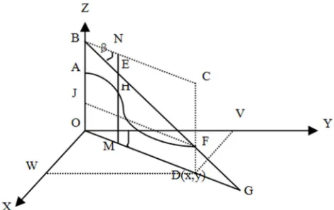
Figure 1. The coordinates of the fire point are calculated according to the rotation angle and pitch angle.
If the fire point is at the center of the image, the rotation angle and pitch angle of the fire point are the rotation angle and pitch angle of the camera optical axis. The following algorithm is given the rotation angle and pitch angle of the camera to solve the geographic coordinates of the fire point, namely the longitude and latitude of the fire point. [15]
First, assuming that the geodetic coordinates and rectangular coordinates are overlapped, the normal north direction (OY axis) is demarcated as the initial zero angle of the digital cloud console, and the direction of fire occurrence is determined by the rotation angle of the cloud console. Secondly, the specific position of the fire point is determined by the pitch angle. The mathematical model was established as shown in figure 1. Line AB is the height of the observation tower, OA is the height of the mountain, F is the imaginary fire point, and D is the projection of point F on the x-y plane of the coordinate system. By solving the length of OD in the line segment, the projection distance of the fire point from the observation tower can be obtained, and the longitude and latitude information of the fire point can be obtained.
gradually approach to zero (because terrain changes irregularly, elevation does not necessarily approach to zero in one direction). When the calculated EH value is less than zero, it means that the selected point M exceeds the projection point D of the fire point F on OG. At this time, go back to the previous selected point and continue to take the point every 100 meters until the calculated EH value is less than zero again. At this time, the error of OM value obtained is within 100 meters. In order to be more accurate, the binary method is used to determine the fire point D. Then solve the coordinates corresponding to point D:
x OD ∗ sin α (1) y OD ∗ cos α (2)
Finally, based on the latitude and longitude of point O and D (x, y) coordinates, it is easy to calculate the longitude and latitude coordinates of point D. As for the value of each elevation MH, whose point M moves forward gradually
through until it is close to point D, can be obtained
conveniently from the obtained rectangular coordinate position of point M, and the corresponding longitude and latitude of the point which can be calculated according to the longitude and latitude of point O.
2.2. The Fire Point Image Is Located at Any Pixel Point
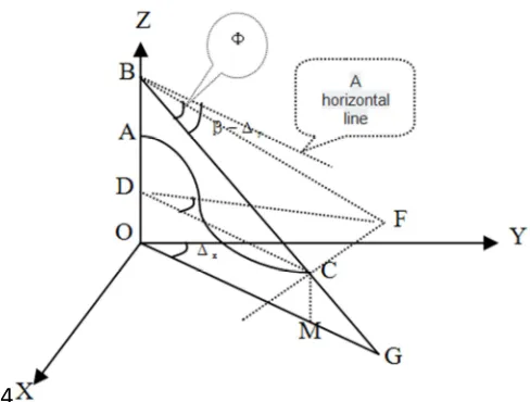
Figure 2. The fire point image P (x, y) is located at any position of pixel coordinates.
Figure 3. Principle of fixed-focus camera imaging.
If the latitude and longitude calculation method of the above fire point at the center of the image is available, the following procedure is to find out the angle difference between the rotation angle and pitching angle of the camera that needs to be adjusted when the fire point is at any point in the image.
As shown in figure 2, a mapping is established between
the plane pixel coordinates and the three-dimensional spatial coordinates. The actual width of the image is w mm, and the
pixel coordinates are wx pixels. The actual height of the
image is h mm and the pixel coordinates are hx pixels. The
top left corner of the image is the zero coordinate position, the horizontal direction is the x pixel coordinate, and the vertical direction is the y pixel coordinate. Suppose the image of the fire point is at the pixel point P (x, y). The camera's horizontal field of view angle is θw, its vertical field angle
isθh, and the focal length of the fixed-focus camera is f mm.
As shown in figure 3, according to the imaging principle of the fixed-focus camera, in the BOD of right triangle, the actual height of the image in mm can be calculated:
OB OD ∗ tan θ /2 (3) h/2 f ∗ tan θ /2 (4) h 2 ∗ f ∗ tan θ /2 (5)
Then, the actual (length mm) ratio of OA/OB in figure 3 is equal to their pixel ratios:
OA/OB h /2 y / h /2 (6) OA / h/2 h 2 ∗ y / h (7) OA h ∗ h 2 ∗ y / 2 ∗ h (8)
Calculate and get the actual distance of OA.
So, if you want to adjust the camera optical axis along the vertical direction to point to the same level, need to adjust the angle for: ∆ y = ∠ODA, can be calculated as follows. In
right triangle AOD:
tan Δ OA /OD (9)
tan Δ h ∗ h 2 ∗ y / 2 ∗ f ∗ h /f h ∗ h
2 ∗ y / 2 ∗ f ∗ h (10)
Then by calculating numerical inverse trigonometric function, angle ∆y can obtain. ∆y is the number which Fire
needs to adjust the angle of the vertical. If the point, as we assume that, is in the center of the upper left is, the fire pitching angle should be adjusted to: β-∆y. If the fire point is
located at the upper right, lower left and lower right of the image center, the corresponding processing can be done. The difference is that when the fire point is above the horizontal line EF (Figure 2), the adjustment angle is reduced. And point below the image center horizontal line EF, the adjustment angle is increased, that is β+∆y.
Similarly, the number of angles from the camera optical axis to point P in the horizontal direction can be obtained as:
tan Φ w ∗ w 2 ∗ x / 2 ∗ f ∗ w (11)
Here Φ not ∆x is used to express point of view, because
here Φ is not the angle which horizontal rotation angle need
to adjust. It's angle ∠CBF in figure 4. If you want to get the
angle of ∠MOY = ∆x which horizontal rotation angle need to
4
Figure 4. The fire point is adjusted vertically to the horizontal line in the center of the image.
According to the above analysis, if CD// OM, F is the actual fire point, then FC ┴ CD FC ┴ CD, that is, FC perpendicular to any line segment through C, that is, FC perpendicular to the plane BCD. It can be seen that angle
∠BCD is equal to the adjusted pitch angle:
∠BCD β Δ (12)
Therefore, according to 2.1, we can calculate the distance OM between point M that is projection of point C and point O, as well as the height CM at point C. In right triangle BCD:
CD OM (13) BC CD/cos β Δ (14)
In right triangle BCF,
CF BC ∗ tan Φ CD/cos β Δ ∗ tan Φ (15)
In a right triangle CDF,
tan ∠CDF CF/CD ( CD/cos β Δ ∗
tan Φ )/CD tan Φ /cos β Δ (16)
tan ∠MOY tan Φ /cos β Δ (17)
tan ΔX tan Φ /cos β Δ (18)
To solve the inverse trigonometric function can get ∆X
degree.
Likewise, if the fire, as we assume that, is in the center of the upper left point, horizontal rotation angle should be adjusted as: α-∆X. As shown in figure 2, if the fire point is
located at the upper right, lower left and lower right of the image center point, corresponding processing can be done. The difference is that when the fire point is on the vertical line BC in the center of the image to the left, the adjustment angle is reduced. The point is located at the central vertical
line BC to the right, the adjustment angle is increased, that is α + ∆X.
At this point, the angle ∆x and ∆y which the fire point P
need to adjust is evaluated. Then, according to the method of 2.1, the longitude and latitude values of the fire point image at any point in the image can be calculated.
Conversely, given the latitude and longitude of the fire point, calculating the horizontal rotation angle and the vertical pitch angle is much easier. As shown in figure 1, no matter the fire point image is located in the center or other image positions, the distance of OD can be calculated by knowing the longitude and latitude of O and fire point F, and the elevation DF of point F can be obtained by consulting the map data of longitude and latitude of F. FJ is parallel and equal to OD. In the right triangle BFJ,
tan∠BFJ BJ/FJ OB OJ /OD OB DF /OD (19)
tan β OB DF /OD (20)
Then by the inverse trigonometric function to calculate theβ, get the pitching angle.
The calculation process of rotation angle α is as follows: given that the longitudes and latitudes of O point and point D, and their longitudes are equal to each other, and both are equal to the longitude of O point, namely the OY axis (due north), the coordinate length OV of point D on the OY axis can be calculated based on the known longitude and latitude of two points. Similarly, if two latitudes are equal, both are equal to the latitude of point O, namely the OX axis, and the length OW and OV of point D in the OX axis can be calculated.
In the right triangle ODV,
tan ∠DOV tan α DV/OV OW/OV (21)
And then we get αby the inverse trigonometric function. At this point, the algorithm is done.
3. Algorithm Programming and Test
Results
Due to the strict requirements for program running time in practical projects, VC++2010 was chosen to implement this algorithm. The following is the test result based on the data provided by party A:
Watchtower longitude: 117.421123, watchtower latitude: 26.910223.
Peak height: 498.5570373535156, tower height: 31.2 meters.
Table 1. Test results of 10 groups of data provided by party A.
elevation Longitude error with party A's data
Latitude error with party A's data
Rotation Angle error with party A's data
Pitch Angle error with party A's data pixel
Two calculation Distance error (m)
69.08 270 0.00166844806 0.0078694835217 -0.008270377865 -0.0541829317498 Image center 69.08
29.38 263 -0.001023300857 0.0318863166278 -0.004846496556 -0.07633245093351 Image center 29.38
20.77 271 -0.001612930703 0.0666358211569 -0.004696567598 -0.01322311369636 Image center 20.77
The data elevation below is the same
Party A only gives two angles of the camera optical axis and cannot calculate the difference. So here's just the calculated angle of fire
The fire is not in the center of the image
24.91 252 -0.000798299876 0.045141260032 174.79673643097 -5.5987999740956 161,125 24.91
9.91 252 -0.000798299876 0.0463243280346 174.761190270161 -5.4442162007669 124,117 9.91
51.06 252 -0.001380059947 0.0463422364352 173.917173757836 -5.44417427372226 175,80 51.06
34.11 252 -0.000537487895 0.0428366861022 175.350966425067 -5.93581060434108 174,163 34.11
46.24 252 -0.00057649032 0.047398714806 174.502211548585 -5.29790387718708 10,7 46.24
46.60 252 0.001499521223 0.0432582020195 178.424079973893 -5.93596647395889 7,240 46.60
20.30 252 0.000456267861 0.0452345091851 176.263197963512 -5.59887354801865 8,115 20.30
Select the actual observation point near Qianling Mausoleum in Qian county, Shaanxi province on Google maps:
Watchtower longitude: 108.2025432587, watchtower latitude: 34.58679621171.
Peak height: 859.19 m, tower height: 31.2 m.
The algorithm operation process is that the rotation Angle
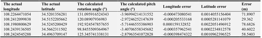
and pitch Angle of the camera are calculated with the actual longitude and latitude coordinates first, and then the longitude and latitude coordinates are verified again through the calculated rotation Angle and pitch Angle. Select 5 groups of actual coordinate points, and the test results are shown in table 2.
Table 2. The test results of five sets of actual data on Google maps.
The actual longitude
The actual latitude
The calculated rotation angle (°)
The calculated pitch
angle (°) Longitude error Latitude error
Error (m)
108.2264471054 34.5201356281 131.095916524343 -3.96994214131552 -0.000473080541 0.0014055156404 71.8907
108.2412099838 34.5152205662 120.08907936983 -2.97246252147639 -0.000205533168 0.0005281141079 29.362
108.1980800629 34.5245200429 192.924547857655 -5.71446555386903 0.000159132852 0.0022051496912 78.6826
108.2439136505 34.5662311502 98.8455509364967 -3.40706558345682 -0.000357962541 0.0002234812578 40.6022
108.2424545288 34.4963709147 125.345741338131 -2.87963541072828 -0.000398474322 0.0010962396525 58.5403
It should be noted that all test data is the same result of repeated calculation, only the calculation time slightly changed.
4. Conclusion
In this paper, forest fire automatic positioning algorithm is researched by the use of camera calibration technology and three-dimensional space analysis on the digital video monitoring system. By means of DEM model, the location of fire point on topographic section is determined by exhaustive search and dichotomy. According to the characteristics of terrain change in forest region, the mapping between plane pixel coordinates and three-dimensional spatial coordinates is established by using the translation method of camera lens optical axis in space, which simplifies the algorithm and improves the calculation accuracy. The characteristic of the algorithm in this paper is to abandon the reference window frequently used in the original general algorithm, simplify the algorithm, reduce the complexity of the algorithm, reduce the intermediate calculation link, avoid the cumulative error of many calculations, improve the accuracy of calculation, and compress the program running time. In this paper, a total of 10+5 groups of data were used for testing, and the calculated fire point position error range was 10-79 meters, with an average error of 42.10 meters. The practical application shows that this localization algorithm can satisfy the
automatic localization of forest fire point and is an important part of the intelligent forest monitoring system.
References
[1] Zhuang Zhemin, Hailong Liao, et al. Study on the Location of Early Fire Source in Inclined Wind Field Based on Weighted Distance Difference Method. Journal of Safety and Environment, 2011, vol. 11 (3): pp. 177-181
[2] Wang S, BERENTSEN M, and KAISER T. Signal Processing for Fire Location Using Temperature Sensor Arrays. Fire Safety Journal, 2005, vol. 40 (8): pp. 689-697
[3] Zhemin Zhuang, XinFeng Zhang, Kalin Li, et al. Method Research Fire Source Locaion Based on Planar Circluar Sensor Arrays. Chinese Journal of Sensors and Actuators. 2009, vol. 22 (8): pp. 1208-1212
[4] Guangqun Yang, Ning Han. Study on Forest Fire Location Method Based on Camera Calibration Technology. Journal of Safety and Environment, 2013, vol. 13 (1): pp. 215-219. [5] Zhemin Zhuang, Hailong Liao, Shengqiang Huang, et al. On the
Early Fire Source Locating Method Base on the Weighted Differential Distance Approach in the Skew Wind Field. Journal of Safety and Environment, 2011, vol. 11 (3): pp. 177-181. [6] Maolin Qiu, Songde Ma, Yi Li. Overview of Camera
[7] Lifan Fei. Establishment of Digital Ground Model (DTM) and Its Application in Agricultural Planning. Regional Research and Development, 1988, 7 (4): pp. 42-43
[8] Jian Zhang, Guangqun Yang, Ning Han GIS- Based Positioning Methods in Video Monitoring of Forest Fires. Forestry Machinery & Woodworking Equipment, 2009, vol. 36 (5): pp. 24-26.
[9] Shouyi Lu, Xiaoming Tang, Shengguo Wang. A Tutorial on the Use of Geographic Information Systems. China Forestry Press. Beijing, China, 1998. p152.
[10] Jianmin Yin. Research on Satellite Remote Sensing Fire Location Algorithm under ArcInfo. Nanjing Meteorological Journal, 2004, vol. 27 (5): pp. 688- 694.
[11] Survey Adjustment Group, School of Surveying and Mapping, Wuhan University. Error Theory and Basis of Measurement Adjustment. Wuhan: Wuhan University Press, 2003. pp. 207.
[12] Andrei B. Utkin, Armando Fernandes, Fernando Simoes, Alesander Lavrov and Rui Vilar. Feasibility of Forest - Fire Smoke Detection Using Lidar. International Journal of Wildland Fire, 2003, (12): pp. 159- 166.
[13] Morsdorf, F., Meier, E., K#tz, B., Itten, K. I., Dobbertin, M., Allg$wer, B. LIDAR - Based Geometric Reconstruction of Boreal Type Forest Stands at Single Tree Level for Forest and Wildland Fire Management. Remote Sensing of Environment, 2004, 92 (3): pp. 353- 362.
[14] Jian Zhang, Guangqun Yang, Ning Han, Yi Liang. Research on Forest Fire Location Algorithm Based on Video Monitoring System. Journal of Safety and Environment, 2009, Beijing, China, vol. 9 (1): pp. 127-130.