IJSRSET173272 | Received : 06 March 2017 | Accepted : 20 March 2017 | March-April-2017 [(3)2: 191-195]
© 2017 IJSRSET | Volume 3 | Issue 2 | Print ISSN: 2395-1990 | Online ISSN : 2394-4099 Themed Section: Engineering and Technology
191
Space Vector Modulation Based Direct Torque Control of
Induction Motor using Matlab Simulink, Maxwell Simplorer
G. S. Gobikha, Dr. S. Allirani
Power Wlectronics and Drives, Department of Electrical Engineering, Sri Ramakrishna Engineering College, Tamil Nadu, India
ABSTRACT
This paper proposes a scheme of space vector modulation based vector control of induction motor drive which is employed in order to achieve high performance of the drive. In vector control speed and torque is controlled independently. In conventional method two-level inverter is used which has a problem of high torque ripple and large harmonics. The proposed converter is configured with a combination of space vector modulation and a three-level inverter. The proposed method features less torque ripple and less harmonics. On the platform of MATLAB and Ansys simplorer SVM-DTC are modelled and simulated.
Keywords : Direct torque control; space vector modulation; Ansys simplorer; Induction machine.
I.
INTRODUCTION
Induction machine (IM) have been widely used in a variety of industrial and residential applications. Right from its beginning its ease of manufacture and its robustness have made it strong for electromechanical energy conversion. The induction motor has many advantages over the rest of motors. The main advantage is that induction motors do not require an electrical connection between the stationary and the rotating parts of the motor.
Thus the induction motor is considered to be the work horse of industry. The advancement of power electronic devices had made it possible to vary the frequency of the voltage or current using control techniques and thus has extended the use of induction motor in variable speed drive applications.
The various speed control methods are pole changing method, stator voltage control, supply frequency control, rotor resistance control, slip power recovery scheme, vector control and intelligent control techniques. The pole changing is only applicable for step change in speed. The drawbacks of this method are, it is bulky and continuous speed tracking is not possible. To avoid this vector control is used in this paper.
Also in conventional 2-level Direct Torque Control (DTC), it has only two levels in the output voltage with a high DC-bus voltage and a high dv/dt. When there are only 6 vectors for outputting the circular flux, the uncertainty of switching frequency leads to voltage fluctuations, torque ripples and large harmonics for solving these problems for 2-level DTC, the controller with a three-level inverter based on space vector modulation is proposed in the project for an induction motor.
The 3-level inverter can provide more voltage vectors to control the motor, and it can reduce the magnitude of the transition so that the voltage waveforms are close to sinusoidal. In order to have a more precise flux and torque control, the PI regulators replace the conventional hysteresis comparators and the space vector modulation module based on the error produces the proper synthesizing vectors instead of the traditional switching table. The entire system is implemented using Matlab-simulink and Ansys-simplorer.
II.
METHODS AND MATERIAL
1. Implementation of SVM-DTC Based Induction Motor Drive
Direct torque control (DTC) is one method used in variable frequency drives to control the torque and hence the speed of three phase AC electric motors. The control strategy involves the calculating of the motors magnetic flux and torque based on the measured voltage and current of the motor.
The characteristics of DTC is based on the position of the inverter switches, which are directly determined by Space Vector (SVM) modulation, rather than using a modulation technique like Pulse Width (PWM) or. The control objective is to keep the motors’ torque and amplitude of the stator flux within pre-specified bounds. The inverter switches are triggered by hysteresis controllers to switch whenever these bounds are violated. The choice of the new switch positions is made using a pre-designed look-up table.
B. Principle of SVM-DTC
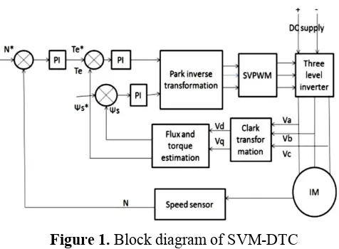
SVM based direct torque control of induction motor consists of inverter, rectifier, filter, PI controller, induction motor. Firstly, the current and voltage of three-phase static coordinate should be measured and be transformed to the two phase coordinate by Clarke transformation, then the flux V and torque Te components of the motor are calculated by the corresponding formulas. And the given torque can be calculated by the PI controller which is consisting of the given speed and the speed of the encoder. The given torque Te* and flux V* can calculate ud and uq components of two phase rotational coordinate by two PI controllers, and Park inverse transform module can transform ud and uq to the two phase static coordinate. By modulating the variables by SVPWM, the three-level inverter can produce different combinations of voltage vectors by changing switch state.
C. Space Vector Pulse Width Modulation
SVPWM method is frequently used in vector controlled and direct torque controlled drives. In vector controlled drive this technique is used for reference voltage generation when current control is exercised in rotating reference frame The sinusoidal reference space vector form a circular trajectory inside the hexagon. The largest output voltage magnitude that can be achieved using SVPWM is the radius of the largest circle that can be inscribed within the hexagon. This circle is tangential to the mid points of the lines joining the ends of the active space vector. Thus the maximum obtainable fundamental output voltage The space vector concept, which is derived from the rotating field of induction motor, is used for modulating the inverter output voltage.
In this modulation technique the three phase quantities can be transformed to (or) stationary frame. From these two - phase components, the reference vector magnitude can be found and used for modulating the inverter output. The process of obtaining the rotating space vector is explained in the following stationary reference frame let the three-phase sinusoidal voltage component be.
Va = VmSinωt Vb = VmSin(ωt-2π/3) Vc = VmSin(ωt-4π/3)
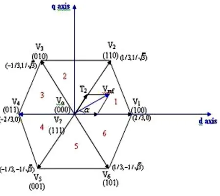
Figure 2. Switching Sector
There is an increasing trend of using space vector PWM (SVPWM) because of their easier digital. Space vector is defined as
Vs= (2/3) (Va+ a Vb+ a2Vc)
Where, A=exp (j 2π/3)
The space vector is a simultaneous representation of all the three-phase quantities. It is a complex variable and is function of time in contrast to the phasor diagram. Phase-to-neutral voltages of a star connected load are most easily found by defining a voltage difference between the star point n of the load and the negative rail of the dc bus N.
VA= Va+VaN VB= Vb+VbN VC= Vc+VcN
Table 1 switching table
In order to obtain fixed switching frequency and optimum harmonic performance from SVPWM, each leg should change its sate only once in one switching period. This is achieved by applying zero state vector followed by two adjacent active state vector in half switching period. The next half of the switching period is the mirror image of the first half. The total switching period is divided into 7 parts, the zero vector is applied for 1/4th of the total zero vector time first followed by the application of active vectors for half of their application time and then again zero vector is applied for 1/4th of the zero vector time. This is then repeated in the next half of the switching period. Thus the symmetrical SVPWM is obtained. For conventional direct torque control, to obtain the corresponding switching signals, the amplitude of the stator flux and the torque errors are sent to hysteresis comparator achieving the control requirements for stator flux and torque. In this paper, in order to reduce torque ripple produced by hysteresis comparator instead of using hysteresis comparator, PI controller can get the d-q axis voltage component respectively and achieve the purpose of continuous adjustment.
III.
RESULTS AND DISCUSSION
A. Simulation results of proposed method using Matlab-simulink
Figure 3. Simulation diagram of SVM-DTC using Matlab
Figure 4. Speed Response Waveform
Figure 5. Torque Response
Figure and shows the speed response and torque response of PI controller based induction motor drive at reference speed of 150 rad/sec at applied load torque TL of 1 Nm. The rise time is observed to be 0.7s
B. Simulation results of SVM-DTC using Maxwell Simplorer
Figure 6. Simulation diagram of SVM-DTC using Simplorer
Figure 7. Torque Response using Simplorer
IV.
CONCLUSION
2-V.
REFERENCES
[1]. Deng Pan, Chong Ren, Wenye Chai, Zhen Zhang. "Motor Direct Torque Control System Based on Three-level Inverter Power Supply". Application of Motor and Control, 2011,07, pp.13-16.
[2]. Fengjun Liu. Multi-level Inverter Technology and Application Mechanical Industry Press, Beijing, 2007
[3]. Stolze P, Karamanakos P, Kennel R, et al. Variable switching point predictive torque control for the three-level neutral point clamped nverterC]//Power Electronics and Applications (EPE), 2013 15th European Conference on. IEEE, 2013, pp.1-10
[4]. Suman K, Suneeta K, Sasikala M. Direct Torque Controlled induction motor drive with space vector modulation fed with three-level inverterC]//Power Electronics, Drives and Energy Systems (PEDES),2012 IEEE International Conference on. IEEE, 2012, pp. 1-6.
[5]. Yangzhong Yang, Yuwen Hu, Direct Torque Control of Induction Motor,Mechanical Industry Press, Beijing, 2009.
[6]. Takashi and T. Noguchi, "A new quick-response and high-efficiency control of an induction motor," IEEE Trans. Industry Applications, vol. IA-22, no.5, pp. 820-827, 2010.
[7]. M. Depenbrock, "Direct self-control (DSC) of inverter-fed induction machines," IEEE Trans. Power Electronics, vol. 3, no. 4, pp.420 429,2008. [8]. U. Baader, M. Depenbrock, and G. Gierse,
"Direct self-control (DSC) of inverter-fed-induction machine—A basis for speed control without speed measurement," IEEE Trans. Ind. Applicat., vol. 28, pp.581–588, May/June 2009. [9]. High dynamic torque control of induction motor