Design, Modeling & Simulation of
Full-pitched Winding Segmented Switched
Reluctance Motor
Susmitha.javvadi
Mtech student, Power electronics & Electrical Drives, Department of Electrical and Electronic Engineering, Gudlavalleru Engineering College ,Gudlavalleru, (A.P.), India
D.Srinivasrao
Associate Professor, Department of Electrical and Electronic Engineering, Gudlavalleru Engineering College, Gudlavalleru, (A.P.), India
Abstract :
Switched reluctance motors (SRM) have advantages of low manufacturing cost, rugged and simple construction
and lesser switches in drive circuit. However, some of its disadvantages are noise, torque ripple and low torque
per unit volume. A few of these limitations, such as noise and low torque to volume have been mitigated in the
segmented switched reluctance machine (SSRM), which uses a full-pitched winding. In this paper, a novel
segmented switched reluctance machine is proposed. The design procedure for segmented switched reluctance
motor is defined and various equations are shown. Finally Matlab/Simulink based model is developed and
simulation results are presented.
Keywords: Reluctance, Switched reluctance Motor, Torque.
1.Introduction
Switched reluctance machines are used in electric vehicles, washers, dryers and aerospace applications
as the machine is brushless, fault tolerant, maintenance free and rugged and simple in construction . However,
some of its limitations are noise, torque ripple and low torque to volume [1-3]. Noise and low torque to volume
have been addressed in the segmented switched reluctance machine (SSRM) [4-6]. SSRM has full-pitched
winding while concentrated winding is used in variable switched reluctance machine (VSRM). This change in
winding arrangement in SSRM reduces length of flux paths as compared to those in VSRM . It is shown there
that SSRM can give double torque than SRM for the same frame size. This increase in torque is because of the
increase in aligned flux, while the torque of SSRM increases with the use of full pitch winding, the end winding
volume of the motor also increases by a factor which depends on the ratio of motor air gap diameter (D) to stack
length (L). For higher values of D/L ratio, as required in in-wheel electric vehicle (EV) or in fans, the copper
loss and end winding volume become significantly higher than those corresponding to concentric winding. This
Fig. 1. VSRM Fig. 2.SSRM
2. Design procedure
The geometry of VSRM and SSRM is shown in Fig. 1 and Fig.2. In order to compare VSRM with SSRM, a 6kW, 2000 rpm machine as in [3] is designed. A 6/4 rotary SSRM is designed for a power capacity identical to that of the VSRM. The material used for the laminations is M19 steel, which is made of non oriented silicon steel [2]. The rotary SRM has a stator pole angle and a rotor pole angle .The speed of the rotary SSRM N in rpm. D is the bore diameter of the rotary SSRM. The power output equation of a rotary SSRM is
P=
k
ek
k
1k
2BAsD2LNrWhere P is the power output ,
k
e is the efficiency,k
d is the duty cycle determined by the currentconduction angle for each rising inductance profile ,
k
1
2/
120
,k
2 is a variable dependent on the operating point and is determined by using aligned saturated inductance and unaligned inductance, B is the stator pole flux density at the aligned position,A
sis the specific electric loading which is defined as ampere conductor per meter of stator inner periphery, L is the stack length of the magnetic core.The bore diameter is obtained from the power output equation as
m s d
e
k
k
k
BA
V
k
P
D
2 1
60
(1)For a power rating of 6kw, 2000rpm
Stack length=114mm Din= 99.94mm
From the above data we can calculate Do/Din =2
Do = 199.98mm
2.1Normal SRM 2.1.1 Stator side design
Stator Pole Arc
2
/
2
r s s
p
p
Stator Pole Width
180
2
s in pwD
S
(3)Stator Yoke Width
L
A
S
yw
sy (4)Stator Pole Height
h
s
D
o
D
in
S
yw2
2
(5)2.1.2. Rotor side design
Rotor Pole Arc
r
s (6)Rotor Pole Width
180
2
in rpw
g
D
R
(7)Rotor Yoke Width
L
A
R
yw
ry (8)Rotor Pole Height
yw sh in r
R
D
g
D
h
2
2
(9)
2.2 SEGMENTED SRM (SSRM) 2.2.1. Stator side design
Stator Pole Arc
2
/
2
r s sp
p
(10)Stator Pole Width
180
2
in sactual pwD
S
(11)Stator Yoke Width
L
A
S
yw
sy (12)
h
D
D
S
ywpoleshowhe
ight
in o
s
2
2
(13)
2.2.2. Rotor side design
Rotor Pole Arc
ractual
2
sactul (14)Rotor Pole Width
180
2
in rpw
g
D
R
(15)Rotor Pole Height
h
r
D
in
g
D
sh
R
yw2
2
(16)
Total number of turns
3
10
2
in ph sD
I
T
A
(17) WhereA
s is Electrical load
Size of the conductor
a
I
J
p4
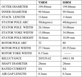
(18)Table 1. Design data of VSRM, SSRM
VSRM SSRM
OUTER DIAMETER 199.89mm 199.88mm
INNER DIAMETER 99.94mm 99.94mm
STACK LENGTH 114mm 114mm
STATOR POLE ARC 30(degrees) 40(degrees)
STATOR POLE WIDTH 26.16mm 34.88mm
STATOR YOKE WIDTH 13.08mm 34.88mm
STATOR POLE HEIGHT 36.8mm 10.09 mm
ROTOR POLE ARC 32 80
ROTOR POLE WIDTH 27.74mm 69.352mm
ROTOR YOKE WIDTH 8.17mm ---
RELUCTANCE 205529.62 69011.98
SHAFT DIAMETER 28mm 28mm
RATED CURRENT 8A 8A
From the above equations the design values for VSRM and SSRM are given in Table 1.
3. Analytical comparison of VSRM and SSRM
For a switched reluctance machine, torque is given by
d
dL
kI
T
2 (19)
d
N
L
(20)From (19) and (20)
d
d
kNI
T
(21)
a ukNIP
T
(22)where P= Number of poles
a
= Aligned fluxu
= Unaligned fluxIn switched reluctance machine
a
uFig. 3. Magnetic circuit of VRSRM Fig. 4. Magnetic circuit of CSSSRM
akNIP
T
(23) There fore
T
a (24)From (24) for the same electrical loading the torques in VRSRM and SSRM are related as
VSRM SSRM
SSRM VSRM
S
S
T
T
Where
S
VSRM andS
SSRM are the minimum reluctances of VSRM and SSRM respectively. Figs. 3 and 4 show the magnetic circuit of each machine in the aligned position. From the equation torque can be increased by decreasing the reluctance. Reluctance can be decreased by increasing the air gap area and decreasing the flux path length. From the above magnetic circuits the reluctance of VSRM is 2,05,529.62 and SSRM is 69,011.98Reluctance in SSRM =1/2.3 (Reluctance in VSRM)
So Torque in segmented SRM=2.3
(Torque in VSRM)In the SSRM torque is double it means output will double at the same time inductance of machine double so it demands double the voltage. So here we can give double the electrical input to the machine and we are getting output power.
4. Matlab/Simulink Modeling
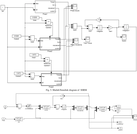
Fig. 5. Matlab/Simulink diagram of SSRM
Fig.5 shows the Matlab/Simulink model of SSRM. It consists of three phase blocks. The Fig. 6 shows the
construction of one phase block. Here we are assuming linear model. To be more complete, the block named
phase1 is described with details that follow. It contains four other blocks, each one associated with a specific
Matlabfunction. They are the following.
4.1 Switch
Switch block permits to assure the power converter commutations at angles theta on, theta off.
4.2 Inductance
Inductance block computes the current on the respective phase inductance according to rotor Position theta and
phase flux. Therefore, one gets phase current I as its output signal, by output block 3 named current1.
4.3 Torque
Torque block computes the torque produced in this phase according to the rotor position theta and the current
value I.
4.4 Modulo pi/2
Each phase inductance has a periodicity of
2
/
N
r degrees. Therefore, it is appropriate to transform the rotorposition angle coming from the mechanical equation so that it is modulo
2
/
N
r4. Simulation results
Fig.6.a. Phase A current in normal SRM Fig.6.b. Phase A current in segmented SRM
Figures 6.a and 6.b shows the one phase currents of VSRM and SSRM respectively. Here current in phase is same for VSRM and SSRM.
Fig.7.aPhase A inductance in normal SRM Fig.7.b Inductance of Phase A in segmented SRM
Fig.8.a. Speed in normal SRM Fig.8.b. Speed in segmented SRM
Figures 8.a and 8.b shows the speed of VSRM and SSRM respectively. VSRM reaching a steady speed of 210 rad/sec in 0.25 sec. SSRM reaching a steady speed of 210 rad/sec in 0.15 sec, this is because the torque of SSRM is double than that of VSRM for same load.
Fig.9.a.Total torque in normal SRM Fig.9.b.Total Torque in segmented SRM
Figures 9.a and9.b shows the total torque of VSRM and SSRM respectively. Comparing to VSRM ,SSRM total torque is double because reluctance is double.
5.Conclustion
A high torque and low weight Segmented Switched Reluctance Machine (SSRM) is proposed. Design for normal SRM and Segmented SRM, comparing the results. Good results can be achieved if the current shape, amplitude, advance angle and the pulse duration are controlled, the cost of manufacturing is less, as concentric coils are easier to wind than full pitched coils. The structure is mechanically robust as rotor segments are embedded in aluminum core. Factors affecting the average torque are identified
.
6.References
[1] T. J. E Miller: Switched reluctance motors and their control, Magna Physics Publications/Oxford university press (1993). [2] R. Krishnan: Switched Reluctance Motor Drives, Industrial Electronics Series, CRC Press (2001).
[3] J. Oyama, T. Higuchi, T. Abe and N. Kifuji, “Novel Switched reluctance motor with segmented core embedded in Aluminum rotor block,” Papers of technical meeting on rotating machinery, IEEJ Trans, Vol.126, No.4, 2006.
[4] Design and Calculation of 75W Three-phase Linear Switched Reluctance Motor, Mr. Myo Min Thet Department of Electrical Power Engineering, Mandalay Technological University, Myanmar.
[5] Naresh Vattikuti, Vandana R and B. G. Fernandes “A high power density Outer rotor segmented switched reluctance motor” Indian Patent Application No 197/MUM/2009.