Journal of Electrical Engineering,
Electronics, Control and Computer Science
JEEECCS, Volume 3, Issue 8, pages 29-34, 2017
Orifice Plate Sizing Calculation
Using a New LabVIEW Technique
Abdalla Milad Faraj 1, Mohammed Ghnume 2, Abdulrahman A.A. Emhemed 3
1,2,3
College of Electronic Technology-BaniWalid, 38645 BaniWalid, Libya.
3
College of Technical Sciences-Bani Walid, Libya.
1
[email protected], 3 [email protected]
Abstract- Orifice plate meter is the most popular type of obstruction flow meter devices, due to its simplicity, low maintenance required, and long life time. This type uses differential pressure technique to measure the flow rate of fluids, which require accurate calculation of the orifice sizing at converting the flow rate into differential pressure. Although, the anciently, continuity and availability of the orifice plate as flow meter; the manual calculation of the plate sizing require more efforts and longtime consumption. This paper presents orifice plate flow meter calculation for a real case study data, based on the related flow calculation equations and their standard experimental tables and curves. These calculation has been computed manually and by using a new designing software program based on the Lab VIEW technique. The flow specification are entered to the program by using the designed user interface front panel, and the results of the calculated plate sizing is appeared in the same front panel, which increase the facilitate of the designed program. On other hand, the code of the program has been secreted in the Lab view block diagram to increase the security of the program. Once the program is completed, and to examine the designed program; the comparative has been taken between the results of both of the theoretical and the programmed calculations. The outcome of this program could help the designer in orifice plate sizing calculation.
Keywords—Orifice plate; sizing calculation; LabVIEW.
I. INTRODUCTION
The orifice plate is the simplest and most widely used differential pressure flow measuring element and generally comprises a metal plate with a concentric round hole (orifice) as shown in Fig. 1. An integral metal tab facilitates installation and carries details of the plate size, thickness, serial number, etc [1-3]. The plate, usually manufactured from stainless steel, Monel, or phosphor bronze, should be of sufficient thickness to withstand buckling (3 - 6 mm).
Fig.1. The orifice plate meter.
The orifice features a sharp square upstream edge and, unless a thin plate is used, a beveled downstream edge. A major advantage of the orifice plate is that it is easily fitted between adjacent flanges that allow it to be easily changed or inspected as the configuration is shown in Fig. 2.
Fig. 2. Orifice plate fitted between adjacent flanges.
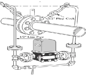
The orifice plate metering system is suitable for measuring the rate of flow of steam, liquids and most gases. In many application, flange taps Fig. 3 are predominantly used for pipe sizes 2 in. (50 mm) and larger. The manufacturer of the orifice flange set drills the taps so that the centerlines are 1 in. (25 mm) from the orifice plate surface. This location also facilities inspection and cleanup of burrs, weld metal, and so on that may result from installation of a particular type of flange. Flange taps are not recommended below 2 in. [4]
Fig.3. Flow measurement using standard manifold. .
II. ORIFICE PLATE CONFIGURATIONS
The orifice plate configurations are classified according to the bore location and it is shape geometric. Indeed, these configuration allows the designers to use it in different flow meter applications. A few shapes and designs have been produced for which the discharge coefficient can be predicted. The most commonly used of plate types are illustrated in Fig. 4.
Fig. 4. Orifice plate configurations, (a) concentric, (b) eccentric, (c) segmental.
III. CONCENTRIC ORIFICE PLATE SIZING CALCULATIONS
This paper is devoted to concentric orifice plate sizing calculation for real data taken from Great Man-Made River Project (GMMRP). Which tabulated in Table I.
TABLE I. CASE STUDY SPECIFICATION
Fluid Water
Pressure (P) 101.334 psig Temperature (T) 95oF Density (σ) 8.345 lb/gal Flow Rate ( ) 951.019 gal/min Diameter (D) 7.874 inch
Maximum differential pressure 196.58 inch W.C(H2O) Orifice Material 304 S.S
Taps Orifice Flanges
Viscosity (cp) 0.01
A. Theoritical Calculation Steps
Although the shape of orifice plate is uniform; but the calculation rule is differ from one fluid to another. So, there are different formulas for different fluids. The formulas and symbols for liquid flow calculation are taken from flow meter engineering textbook [5][6].
The diameter ratio or beta (sometimes referred to as the beta ratio) is the ratio between the diameter of the orifice or throat of device to (d) that of the inner pipe diameter(D) [7]. which defined by where:
(1)
The operating figure ( ) from which ( can be obtained for measurement of liquid flow rate is defined by:
√ √ (2)
Where, is ratio of orifice bore area at flowing temperature at 68 , is manometer correction factor, is specific gravity at flowing temperature,( is specific gravity at 60oF, is viscosity or Reynolds number correction, is correction for compressibility of the liquid, and is maximum differential pressure ,inches W.C. is constant depending on units of measurements , and
( maximum flow rate in units of corresponding
with .
The following steps should be taken to evaluate the orifice plate sizing for the mentioned case study which are:
1. Firstly, the units of flow measurement can be defined from Table II as U.S (Gal/Minute), which defined by ( 5.6670)[5][6].
Table .II CONSTANTS FOR LIQUID FLOW MEASUREMENT
Flow Time Cu. Ft. U.S. Gal. Imp. Gal. Barrels (42 Gal.) Barrels (50 Gal.)
Second 0.01263 0.09446 0.07865 0.002249 0.001889 Minute 0.7576 5.667 4.719 0.1349 0.1133
Hour 45.46 340.0 283.1 8.096 6.801 24 Hrs. 1091 8161 6795 194.3 163.2
2. Because, the material of the plate is recommended from stainless steel type 304 and flowing temperature 95oF as mentioned in Table I; the ratio of orifice bore area( can be taken from (Spink, Table 7 pp.156) [5] which equal to (1.000).
3. The manometer correction factor( ) should be taken equal to (1.000) for choosing the orifice plate as the head flow meter element((Spink, Table 8 pp.157) [5])
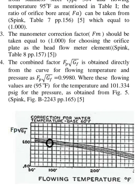
4. The combined factor √ is obtained directly from the curve for flowing temperature and pressure as √ 0.9980. Where these flowing values are (95 oF) for the temperature and 101.334 psig for the pressure, as obtained from Fig. 5. (Spink, Fig. B-2243 pp.165) [5]
5. The specific gravity of the water ( ) at the normal temperature(60-70 oF) is taken from the normalized value at (1.000) [5].
6. Now, the first calculation of the operating figure ( ) at ignoring the effect the viscosity or Reynolds number correction ( ) can be obtained as:
√ √
√
7. Then the ratio of orifice bore to inner pipe diameter ( ) with ignoring ( ) for the calculated operating figure ( ) in step 6 can be calculated from Fig. 6 by using the interpolation equation.(for more details about Fig. 6, (Spink, Table 12 pp.171) [5].
Fig. 6. S values crossponding to ratio.
By referring to the above figure, the value of the calculated is between (0.1929-0.1937), the interpolation procedure can be done by:
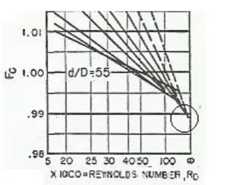
8. Now, recalculating ( ) in present of the effect viscosity or Reynolds number correction factor ( ) for 7.874 inch pipe diameter and , which can be read out from Fig. 7 after Reynolds number calculation for the given flow rate (pph) and it is viscosity(cp) . (Spink, Fig. B-2288 pp.223) [5]
Where:
951.019 gal/min = 951.019 *500.72426 = 476198.292 pph
Thus:
= 3822165.615
As seen from Fig. 7, the calculated located at the end of the curve (infinity region).
0.988.
Thus,
Fig. 7. the Reynolds number correction.
9. The desired ratio of orifice bore to inner pipe diameter can be calculated from Fig. 8 by using the same manner in step 7 (Spink, Table 12 pp.171) [5].
Fig. 8. S values corresponding to ratio.
10. Finally the bore diameter ) can be calculated as:
B. Orifice Plate Bore Calculation Using a New LabVIEW Technique.
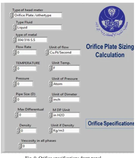
In this section, a new software tool designed to calculate the orifice plate bore diameter. This program configured by using Laboratory Virtual Instrumentation Engineering Workbench (Lab VIEW). This program is a graphical (icons) language for instrumentation programming (analysis), where its FRONT PANEL (User Interface) arranged by two windows, which are orifice specification and
calculation results as shown in the figures 9 and 10.
Fig. 9. Orifice specifications front panel.
The first front panel is contents all orifice plate specification as shown in fig. 9. The various equations are fully interlocked in this LabVIEW Technique. The orifice specifications adjusted manually for display the calculation results front panel which contents of inner pore diameter ( ), ratio of orifice bore to inner pipe diameter and other correction factures such as ( ) as shown in Fig. 10.
Fig. 10. Calculation results front panel.
C. The Comparative Results Between The Designed Calculation Rule and Another Industrial Techniaque (Flow Calc32 EC)
The industrial version Flow Calc32 EC is shown in Fig. 11. The calculated pore diameter can be obtained by interring the specification of the flow rate data in the cross ponding front panel fields, such as type of fluid and it’s temperature, etc.
Fig. 11. Flow Calc32 EC software.
In present time, the flow calculation for case study (GMMRP) are compared by using the three calculation rules, which summarized as shown in the following Table III.
TABLE III.THE COMPARATIVE ASSESSMENT BETWEEN CALCULATION RESULTS
Calculation method Results
Flow Calc32 EC Theoretical Calculation
Lab VIEW calculation 0.552 0.5526 0.548 (inch) 4.347 4.351 4.320
According to the comparative table, the bore diameter in three calculation rules are mostly similar. Thus the new program is sufficient to evaluate the orifice plate sizing calculation.
IV. CONCLUSION
REFERENCES
[1] R. W. Miller, Flow Measurement Engineering Handbook, 3rd ed., McGrawHill, New York, 1996.
https://books.google.com.ly/books?id=0e9RAAAAMAAJ&q =Miller,+Flow+Measurement+Engineering+Handbook,+3rd+ ed.,+McGrawHill,+New+York,+1996.&dq=Miller,+Flow+M easurement+Engineering+Handbook,+3rd+ed.,+McGrawHill, +New+York,+1996.&hl=ar&sa=X&ved=0ahUKEwj71MSe0I XZAhWBr6QKHQs1Dy4Q6AEIJzAA
[2] B. G. Liptak, Instrument Engineers: Process Measurement and Analysis,, Handbook, 4th ed., Vol (1), 2003.
ftp://ftp.unicauca.edu.co/Facultades/FIET/DEIC/Materias/Inst rumentacion%20Industrial/Instrument_Engineers__Handbook Process_Measurement_and_Analysis/Instrument%20Enginee rs'%20Handbook%20%20Process%20Measurement%20and %20Analysis/1083fm.pdf
[3] B Walt, Instrumentation Reference Book, 3rd ed, Elsevier Science, 2003.
https://www.sciencedirect.com/science/book/9780750671231
[4] J. D. Marrelli, U.S. Patent No. 5,597,961. Washington, DC:
U.S. Patent and Trademark Office. 1997.
[5] L. K. Spink, Principles and Practice of Flow Meter Engineering, 1967 Ninth Edition, The Foxbro Company.
https://books.google.com.ly/books?id=7hRAAAAMAAJ&dq =Principles%20and%20Practice%20of%20Flow%20Meter% 20Engineering%201967&hl=ar&source=gbs_book_other_ver sions
[6] W.G. Andrew &H.B. Williams, Applied Instrumentation in the Process Industries, Second Edition, Gulf Publishing Company, 1982.
https://books.google.com.ly/books/about/Applied_Instrument ation_in_the_Process_I.html?id=I9xTAAAAMAAJ&redir_es c=y
[7] Good Practice Guide: an Introduction to Differential-Pressure Flow Meters, Report by TUV NEL, East Kilbride, Glasgow, G75 0QF, UK.