All Rights Reserved © 2013 IJARCSEE
308
An Insight Comparison of Serial Communication
Protocols
Gaurav Khurana
1, Umesh Goyal
21,2
Electronics and Electrical Communication Department, PEC University of Technology, Chandigarh, India.
Abstract— An Embedded System consists of a large number of integrated circuits. For proper functioning of the system, these Integrated circuits need to communicate with each other. This communication is done using a number of universally accepted protocols as per the system requirement. These protocols include Inter-Integrated Circuit protocol, Serial Peripheral Interface, MOD bus protocol, Controller Area Network bus protocol and others. This paper describes the basics of these protocols and also compares them with the help of some performance parameters like speed, data rate, error handling and at different layers of OSI model like physical layer, data link layer and application layer. After reading this paper, one can choose the suitable serial bus protocol as per the requirement of application.
Index Terms
—
Modbus, CAN bus, CANopen, I2C, SPII. INTRODUCTION
Any Embedded system is generally consisting of one or more micro-processors or micro-controller and a number of peripherals IC‘s like EEPROM, Real time clock (RTC), watchdog timer and sensors etc. For proper functioning of the system, these IC‘s need to communicate with microcontroller. The application of parallel buses to all interfaces however, is not always a good trade-off between cost, convenience and required performance. The tried and true serial bus is often a better solution when data transfer, is required between IC‘s on a board so Serial communication is preferred for this inter-IC communication because of obvious reason of simplicity, low cost and minimum requirement of I/O pins. Many serial communication protocols like RS-232/RS-485, I2C, SPI, Modbus and CAN bus etc. compete for use in embedded systems. All these protocol has their own advantages and limitations and selection of a particular protocol for an application needs an insight comparison of all available options, so this paper compares some of the popular serial communication protocols and highlights their features and specifications which can make the selection task easier. After the brief introduction of each protocol, this paper will compare these protocols.
II. PROTOCOL OVERVIEW
A. I2C(Inter-Integrated Circuit)
I2C stands for Inter-Integrated Circuit. I2C is a synchronous master/slave protocol that allows a master device to initiate communication with a slave device. I2C is a two wire (DATA (SDA) and Clock (SCL)) bidirectional communication protocol and Clock is generated by the master
to control the data transfer but slow slaves may hold the clock pins low to prevent the data transfer. This is done by a device that has become too busy to accept more data. I2C works by having a pull-up resistor on the line and only devices pull the line low during communication. When the bus is free, both lines are HIGH [1].
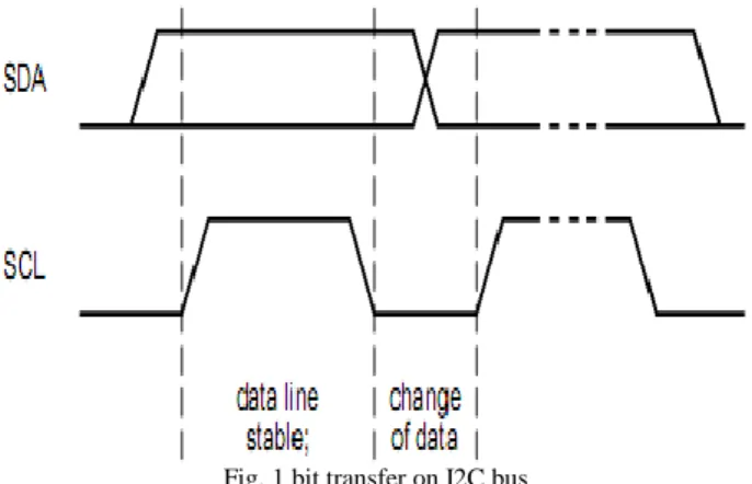
Fig. 1 bit transfer on I2C bus
The data on the SDA line must be stable during the HIGH period of the SCL line. The state of the data line can only change when SCL line is LOW.
Fig. 2 START and STOP conditions
HIGH to LOW transition on the SDA line while SCL is HIGH is START condition and LOW to HIGH transition on the SDA line while SCL is HIGH is STOP condition. START and STOP conditions are always generated by the master. The bus is considered to be busy after the START condition. The bus is considered to be free again a certain time after the STOP condition [2].
309
All Rights Reserved © 2013 IJARCSEE and each byte has to be followed by an acknowledge bit.
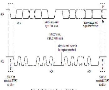
There no restriction on the number of bytes transmitted per transfer. Acknowledge is transferred during the 9th clock pulse and during this clock pulse, transmitter releases the SDA line HIGH then receiver must pull down the SDA line to indicate the positive acknowledgement.
Fig. 3 Acknowledgement of I2C bus
When a slave doesn‘t acknowledge the slave address (for example, it‘s unable to receive or transmit because it‘s performing some real-time function), the data line must be left HIGH by the slave. The master can then generate either a STOP condition to abort the transfer, or a repeated START condition to start a new transfer.
Fig. 4 Data transfer on I2C bus
I2C is a multi-master protocol and all the masters are capable of generating their clocks so there is a need of clock synchronization and arbitration. Clock synchronization is performed using the wired-AND connection of I2C interfaces to the SCL line.
The SCL line will be held LOW by the device with the longest LOW period. Devices with shorter LOW periods enter a HIGH wait-state during this time [3].
Fig. 5 Clock Synchronization
A master may start a transfer only if the bus is free. Two or more masters may generate a START condition simultaneously then arbitration take place on the SDA line while SCL line is at HIGH level. If first master which transmits a HIGH level, while another master is transmitting a LOW level will switch off its DATA output stage because the level on the bus doesn‘t correspond to its own level.
Fig. 6 Arbitration process in I2C Bus
B. SPI (Serial Peripheral Interface)
All Rights Reserved © 2013 IJARCSEE
310
(SS), are needed for an SPI. Data is transferred most significant bit first.
Fig. 7 SPI Master Slave Interconnection
With SS active low, the corresponding peripheral slave device is selected. Master always provides clock signal to all devices on a bus whether it is selected or not. Only one master must be active on a bus at a time. The SPI protocol operates in full duplex mode, when input and output data transfers on both lines simultaneously. The unselected devices keep the SDO lines in hi-Z state and therefore inactive.
Fig. 8 Single Master, Multiple Slaves SPI Implementation
Since the clock serves as synchronization of the data communication, there are four possible modes that can be used in an SPI protocol, based on clock polarity (CPOL) and clock phase (CPHA) as shown in Table I.
Table I SPI modes
SPI Modes CPOL CPHA
0 0 0
1 0 1
2 1 0
3 1 1
If the phase of the clock is zero (i.e. CPHA = 0) data is latched at the rising edge of the clock with CPOL = 0, and at the falling edge of the clock with CPOL = 1. If CPHA = 1, the polarities are reversed. Data is latched at the falling edge of
the clock with CPOL = 0, and at the rising edge with CPOL = 1. The SPI has one error condition: If the SS input becomes low while the SPI is configured as a master, it indicates a system error where more than one master may be trying to drive the MOSI and SCK lines simultaneously. This condition is not permitted in normal operation.
C. MOD bus
Modbus is a serial communications protocol published by Modicon in 1979. MODBUS Protocol defines a standard message structure with universal recognition and usage regardless of the type of networks over which any two devices communicate. It is a master-slave communication protocol. It describes the process a master uses to request an access to slave, and how the slave will respond to these requests, and how errors will be detected and reported. Master can initiate transactions (called ‗queries‘) and slave respond by supplying the requested data to the master, or by taking the action requested in the query. The master can address individual slaves, or can initiate a broadcast message to all slaves. Slaves return a message (called a ‗response‘) to queries that are addressed to them individually. Responses are not returned to broadcast queries from the master.
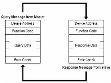
Fig. 9 Modbus master-slave query-response cycle
Master‘s query consists of slave device (or broadcast) address, a function code defining the requested action, any data to be sent, and an error checking field. The slave‘s response contains fields confirming the action taken, any data to be returned, and an error–checking field.
Table II Modbus data format
Protocol data unit (PDU ) Application Data unit(ADU)
1 byte 1 byte Variable 2 bytes Address
field
Function field
Data field Error checking
311
All Rights Reserved © 2013 IJARCSEE If the slave makes a normal response, the function code in
the response is an echo of the function code in the query. If an error occurred in receipt of the message, or if the slave is unable to perform the requested action, the slave will construct an error message by modifying the function code (set the MSB of function code) to indicate that the response is an error response, and the data bytes contain a code that describes the error.
Modbus protocol can be established in two kinds of transmission mode: ASCII mode or RTU mode. In ASCII mode, each 8–bit byte in a message is sent as two ASCII characters. In RTU mode, each 8–bit byte in a message contains two 4–bit hexadecimal characters. The main advantage of RTU mode is that its greater character density allows better data throughput than ASCII for the same baud rate. Modbus protocol has the parity check, besides, the ASCII mode uses the LRC check, and the RTU mode uses 16 CRC check.
Table III is a comparison between ASCII mode and RTU mode.
Table III
Comparison of ASCII and RTU mode
Mode Beginning
marks
Ending
marks
Check Transmission
efficiency
ASCII
: (colon)
CR,LF
LRC
low
RTU
Non
Non
CRC
High
According to Table I, the data transmission rate of ASCII mode is a little lower than RTU mode. So, when need to send large data, user always uses RTU mode. The standard Modbus protocol is to use a RS-232C compatible serial interface, which defines the port pin, cable, digital signal transmission baud rate, parity.
D. CAN bus(Controller Area Network)
The CAN bus was developed by German automotive system supplier Robert Bosch in mid-1980‘s for automotive applications in automobile systems. CAN is an International Standardization Organization (ISO) defined serial communications bus originally developed for the automotive industry to replace the complex wiring harness with a two-wire bus. The specification calls for high immunity to electrical interference and the ability to self-diagnose and repair data errors. These features have led to can‘s popularity in a variety of industries including building automation, medical, and manufacturing.
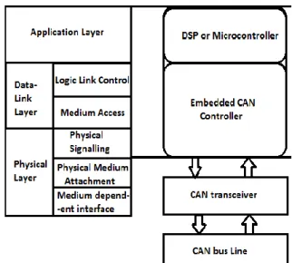
The can communications protocol, iso-11898, describes how information is passed between devices on a network and conforms to the open systems interconnection (OSI) model that is defined in terms of layers. Actual communication between devices connected by the physical medium is defined by the physical layer of the model. The ISO 11898 architecture defines the lowest two layers of the seven layer OSI/ISO model as the data-link layer and physical layer as shown in figure 10.
Fig. 10 The layered ISO standard 11898 architecture
The CAN communication protocol is a carrier-sense, multiple-access protocol with collision detection and arbitration on message priority (CSMA/CD+AMP). CSMA means that each node on a bus must wait for a prescribed period of inactivity before attempting to send a message. CD+AMP mean that collisions are resolved through a bit-wise arbitration, based on a pre-programmed priority of each message in the identifier field of a message. The higher priority identifier always wins bus access, that is, the last logic-high in the identifier keeps on transmitting because it is the highest priority. For can, the dominant bit is logic ‗0‘ and recessive bit is logic ‗1‘.
Fig.11 Arbitration on a CAN Bus
All Rights Reserved © 2013 IJARCSEE
312
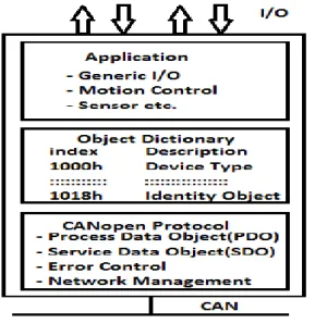
is unique for any CANopen device. It is comparable to a parameter list and offers the access to the supported configuration- and process data. To gain access to the object dictionary, each CANopen device has to implement a CANopen protocol stack. This CANopen protocol stack is software, which is usually implemented on the same micro-controller that is used by the device's application software.
Fig. 12 Internal Device Structure
III.COMPARISONOFSERIALPROTOCOLS The protocols described above are compared with each other and the following points have been noted. This comparison between different serial protocols helps us in choosing the best protocol as per the requirement of our application.
TABLE IV COMPARISON TABLE
Parameter I2C SPI MODbus CAN bus
Standardizati on Not Applicable Not Applicable Not Applicable ISO-11898: 2003 Standardizati on Organization Philips Semiconduc tor
Motorola Modicon
Inc.
BOSCH enterprises
Architecture Master-slave architecture
semaphore/t hread architecture
Single-Master or Multi-Master bus Master-slave architecture Single Master Applicatio n layer messaging protocol Master- Slave Architectur e Single Master or Multi-Master bus Physical layer 2-wire connection:- SDA, SCL 4-wire connection:-
SDI, SDO,
SCLK, SS
Balanced
mode of
Transmissi on
RS 232
serial interface
2-wire connection :- CANH, CANL
Implement ation
Peer to
peer Communic ation TCP/IP over Ethernet
Data link
layer
Three
Modes of
operation: Standard, Fast, High Speed
Not limited to 8-bit words; Arbitrary
choice of
message size, content
Two types of message frames are used: ASCII mode and RTU mode
Two types
of data
formats: Standard CAN, Extended CAN Application layer Synchronou s Checksum ensures proper end-to-end communicat ion Synchronous Checksum ensures proper end-to-end communicatio n
Does not give time stamped events.
Does not provide polled report by exception Checksum ensures proper end-to-end communic ation Synchrono us Communic ation using Synch objects Checksum ensures proper end-to-end communic ation Device Addressing
Each device has a unique 7-bit or 10-bit address
No Slave
addressing Addresses field contains two characters (ASCII mode) or 8 bits (RTU mode)
Valid address in range 1-247
Address 0 used for broadcast standard 11-bit identified extended2 9-bit identifier Configuratio n parameters required
Signalling rate up to 3.4Mbps Several Mbits/sec data rates Baud rate Mode ASCII or RTU
Parity mode
signalling rates from 125 kbps to 1 Mbps
Error detection
CRC CRC, no
acknowledge ment or flow control mechanisms are provided
CRC CRC, Bit
stuffing, ACK , and others
Performance Lowest More than
I2C
313
All Rights Reserved © 2013 IJARCSEE
REFERENCES
[1] I2C Protocol Design for Reusability, Zheng-wei Hu , Information Processing (ISIP), 2010 Third International Symposium on Digital Object Identifier: 10.1109/ISIP.2010.51 Publication Year: 2010 , Page(s): 83- 86.
[2] Personal digital assistant (PDA) based I2C bus analysis, Bruce, J. W. , Gray, Matthew Alan ; Follett, Randolph F. Consumer Electronics, IEEE Transactions on Volume: 49 , Issue: 4 Digital Object Identifier: 10.1109/TCE.2003.1261257 Publication Year: 2003 , Page(s): 1482 - 1487.
[3] Improvement of I2C Bus and RS-232 Serial Port under Complex Electromagnetic Environment Chai Yan-jie ; Sun Ji-yin ; Gao Jing ; Tao Ling-jiao ; Ji Jing ; Bao Fei-hu Computer Science and Software Engineering, 2008 International Conference on Volume:4 Digital Object Identifier: 10.1109/CSSE.2008.843 Publication Year: 2008 , Page(s): 178- 181
[4] ―Introduction to Serial Peripheral Interface‖, by David Kalinsky and Roee Kalinsky, Embedded Systems Programming, 02/01/2002. [5] H. Boterenbrood, ―Canopen high-level protocol for CAN-bus,‖
NIKHEF, Amsterdam, March 20, 2000.
[6] Modbus Application Protocol Specification V1.1b, Modbus-IDA, December 2006, pp. 1-51, [Online] available at http://www.modbus-IDA.org.
Gaurav Khurana, born on 07 September 1987 at Ambala Cantt, Haryana, India. He is currently pursuing Masters in Engineering in Electronics field from PEC University of Technology, Chandigarh, India. His Masters in Engineering will be completed by June, 2013. He has completed his Bachelors of Technology in Electronics and Communication Engineering from Ambala college of Engineering & Applied research, mithapur, Haryana, India in year-2009.
The major field of his work is related to Microcontroller and Embedded Systems, Digital Signal Processing and digital communication.
Umesh Goyal, born on 18 July 1990 at Moga, Punjab, India. He is currently pursuing Masters in Engineering in Electronics field from PEC University of Technology, Chandigarh, India. His Masters in Engineering will be completed by June, 2013. He has completed his Bachelors of Technology in Electronics and Communication Engineering from Chitkara Institute of Engineering & Technology, Punjab, India in year-2011.
The major field of his work is related to Electronic Embedded Systems, Digital Signal Processing, and System Design.