Spatial Interference Alignment in Relay-Assisted
Multi-Cell Multi-User Networks
Ali Golestani
Department of Electrical Engineering K.N. Toosi University of Technology
Tehran, Iran [email protected]
Ali H. Bastami
Department of Electrical Engineering K.N. Toosi University of Technology
Tehran, Iran [email protected] Kamal Mohamed-pour
Department of Electrical Engineering K.N. Toosi University of Technology
Tehran, Iran [email protected]
Received: October 16, 2016- Accepted: December 27, 2016
Abstract—In this paper, the spatial interference alignment (IA) is investigated in the downlink (DL) of a relay-assisted multi-cell multi-user network. The transmission from the base station (BS) to the mobile station (MS) takes place in two phases with the help of the selected relay station (RS). The closed-form IA algorithms are employed in both the BS to RS and RS to MS links. The performance of this cooperative scheme is analyzed in terms of the sum rate and the sum degrees of freedom (DoF) for the amplify-and-forward (AF) and decode-and-forward (DF) relaying schemes. The simulation results of the sum rate show that the DF scheme significantly outperforms the noncooperative min-leakage and max-SINR iterative algorithms over the entire range of SNR, and the AF scheme performs very close to the min-leakage algorithm. Moreover, the DF scheme outperforms the noncooperative closed-form IA algorithm in the low and medium-SNR regimes.
Keywords-Cellular network, degrees of freedom, interference alignment, relay, sum rate.
I. INTRODUCTION
The co-channel interference has become the key challenge in the new generations of cellular communication networks that employ the frequency reuse factor (FRF) of unity. Especially, the inter-cell interference coming from the adjacent cells significantly diminishes the spectral efficiency of the cell-edge users. Implementing a smart interference management technique is a good solution to increase the spectral efficiency of the cell-edge users [1].
Interference alignment (IA) is a cooperative transmission and/or reception technique that can establish a high multiplexing gain by effectively decreasing the interference level in a multi-user system [2]. With the help of the IA technique, the multi-user interference channel can achieve its maximum degrees of freedom [3]. Therefore, in the high-SNR regime, the IA technique can make the sum-rate of the cellular system close to the sum-capacity of the system [4]. In a dense cellular network, some user terminals may be located in the coverage holes of the base station (BS). This situation is more probable for the cell-edge users. In these situations, utilizing the
relay nodes can be very helpful to improve the coverage area of the BS. The relay nodes can be selected among the idle nodes that are located in the coverage area of the BS, and the communications can be indirectly performed with the help of these intermediate nodes.
The combination of the cooperative communication schemes and the IA techniques is an appropriate way to simultaneously overcome the interference and fading impairments of the channel [5]-[10]. The problem of energy spectral efficiency maximization in the downlink (DL) of a multi-user multi-relay multi-cell time-division-duplex (TDD)-based network has been investigated in [5]. In [6], for a two-cell two-user relay-aided network, an IA scheme has been proposed in which the degrees of freedom can reach to its upper bound. The duality of the IA in the uplink (UL) and DL transmissions of a multi-cell multi-user relay-aided network with single-antenna users has been investigated in [7]. In [8], an enhanced relay-aided interference alignment (eRIA) scheme has been proposed in which a super relay is employed for the IA purposes between the BSs of a cellular network and their corresponding users. In [9] and [10], two IA-based two-hop protocols have been designed for the one-user-per-cell and two-user-per-cell scenarios, respectively, where the relay node and the cell-edge users are located at around the junction of the cells.
In this paper, the spatial IA is investigated in the DL of a relay-assisted multi-cell multi-user network. The transmission from the BS to the mobile station (MS) takes place in two hops with the help of the selected relay station (RS) which is chosen among the set of potential relay nodes. All the terminals of the network are equipped with multiple antennas. Accordingly, the first phase of transmission from the BSs to the selected RSs is modeled as a multiple-input multiple-output (MIMO) interfering broadcast channel (IFBC) and the second phase of transmission from the selected RSs to the MSs is modeled as a MIMO 𝐾 × 𝐶-user interference channel, where 𝐶 is the number of cells and 𝐾 is the number of MSs per cell. In both phases of transmission, the closed-form IA algorithms are employed. The performance of this cooperative scheme is analyzed in terms of the sum rate and the sum degrees of freedom (DoF) for the amplify-and-forward (AF) and decode-and-amplify-and-forward (DF) relaying strategies. The simulation results of the sum rate show that the DF scheme significantly outperforms the noncooperative min-leakage and max-SINR iterative algorithms over the entire range of SNR, and the AF scheme performs very close to the min-leakage algorithm. Moreover, the DF scheme outperforms the noncooperative closed-form IA algorithm in the low and medium-SNR regimes. Also, the DoF analysis shows that the sum degrees of freedom in the first and second phases of the proposed schemes can achieve the optimal value under some special configurations.
The rest of this paper is organized as follows. Section II presents the system model and the protocol description. Section III analyzes the performance of the system in terms of the sum rate and the sum DoF. Section IV presents some simulation results and
numerical examples. Finally, Section V summarizes the main results of the paper.
Notation: We use boldface lowercase letters for
vectors and boldface uppercase for matrices. (. )𝑇 and
(. )𝐻
denote the transpose and the conjugate transpose, respectively. For the matrix 𝐀, tr(𝐀) denotes the trace of 𝐀, rank(𝐀) denotes the rank of 𝐀, det(𝐀) denotes the determinant of 𝐀 and 𝜆𝑖(𝐀) denotes the 𝑖th largest
eigenvalue of 𝐀. [𝑎]+= max(𝑎, 0)
, ⌈𝑎⌉ denotes the smallest integer greater than or equal to 𝑎 and ⌊𝑎⌋
denotes the largest integer less than or equal to 𝑎. ℂ
represents the set of complex numbers. 𝑎 ≡ 𝑏 is the remainder of the division of 𝑎 by 𝑏.
II. SYSTEM MODEL AND PROTOCOL DESCRIPTION
In this section, we present the system model under investigation and the IA-based cooperative protocol.
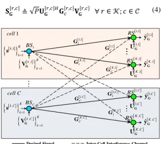
Fig. 1. System model
A. System Model
We consider a cellular network with 𝐶 cells and the FRF of 1. Each cell consists of one BS located at the center of the cell, 𝐾 MSs and 𝐾 × 𝐿 half-duplex RSs, as shown in Fig. 1. All the terminals operate over the same frequency band. The DL transmission from the BS to the MS is under investigation. It is assumed that there is no direct link between the BS and the MS, and hence, each MS receives the BS signal with the help of the selected RS which is chosen among 𝐿
potential relay nodes. It is assumed that the BS and the MS are equipped with 𝑀𝑏 and 𝑁𝑚,𝐅 antennas,
respectively, and each RS is equipped with 𝑀𝑟
transmit and 𝑁𝑟 receive antennas.
In Fig. 1, RS[𝑟,𝑐] and MS[𝑟,𝑐] denote the the 𝑟th RS
and MS of cell 𝑐, respectively. 𝐆𝑏[𝑟,𝑐] is an 𝑁𝑟× 𝑀𝑏
matrix that characterizes the MIMO channel from the BS of cell 𝑏 to RS[𝑟,𝑐]
. Similarly, 𝐅[𝑟,𝑏][𝑘,𝑐] is an 𝑁𝑚,𝐅×
𝑀𝑟 matrix that characterizes the MIMO channel from
RS[𝑟,𝑏] to MS[𝑘,𝑐].
1,1
RS
L,1
RS 1
BS
1 K1L,1
RS
KL,1
RS
1,C
RS
L C, RS
C
BS 1K1L C,
RS
KL C, RS 1
1 1,
G
1 1
2,
G
1
1 1KL,1
G
1
1 ,
KL
G
1,C C
G
2,C C
G
1 K1L C,
C
G
,C C
KL
G
1,1
C
G
2,1
C
G
1 K1L,1
C
G
,1 C KL G , 1 1C G , 1 2C G
1
1 1KL C,
G , 1 KL C G cell C 1 cell
1,1
MS
K,1 MS
1,C
MS
K C, MS
cell C
1
cell 1,11,1
F
L1,1,1
F
,1 1 K1L,1
K
F
KL,1,1 K
F
1 1 , , K C C K L F
,,C C KL
K
F
1,1,
C C
F
1,, C L C
F
Inter-Cell Interference Channel Intra-Cell Interference Channel Inactive Link
1,1
RS
L,1
RS
1 K1L,1
RS
KL,1
RS
1,C
RS
L C, RS
1 K1L C,
RS
KL C, RS Desired Signal (Active Link)
It is assumed that the wireless channels suffer from the frequency non-selective quasi-static fading plus shadowing [11] and additive white Gaussian noise (AWGN). Under Rayleigh fading assumption, each entry of the matrices 𝐆𝑏[𝑟,𝑐] and 𝐅[𝑟,𝑏][𝑘,𝑐] is a zero-mean circularly symmetric complex Gaussian random variable and the additive noise is distributed as
𝒞𝒩(0, 𝜎𝑛2).
B. Protocol Description
1) Relay Selection: In the proposed scheme, the BS sends its message to the MS with the help of a single relay node. As described in the previous subsection, corresponding to each MS, there are 𝐿
potential relay nodes. Thus, we should first select the best relay node based on an appropriate criterion. In this paper, we select the best relay node such that the minimum SNR of the BS-RS and RS-MS links is maximized [12]. This criterion can be formulated as
rs[𝑘,𝑐]= argmax
1+𝐿(𝑘−1)≤𝑟≤𝑘𝐿
min (tr(𝐆𝑐[𝑟,𝑐]𝐆𝑐[𝑟,𝑐]𝐻), tr(𝐅[𝑟,𝑐][𝑘,𝑐]𝐅[𝑟,𝑐][𝑘,𝑐]𝐻)) ∀ 𝑘 ∈ 𝒦 ≜ {1, ⋯ , 𝐾}; 𝑐 ∈ 𝒞 ≜ {1, ⋯ , 𝐶}
(1)
where rs[𝑘,𝑐] is the selected RS corresponding to
MS[𝑘,𝑐]. Considering all the interfering signals, we
conclude that the first hop channel is a MIMO IFBC and the second hop channel is a MIMO 𝐾 × 𝐶-user interference channel.
2) First Phase: In the first phase of the protocol, all the BSs transmit and the selected RSs listen. Let us focus on the signal transmitted by the BS of cell 𝑐. During the first hop, this BS transmits 𝑑[𝑟,𝑐]
independent data streams to rs[𝑟,𝑐], where 𝑑[𝑟,𝑐]≤
min{𝑀𝑏, 𝑁𝑟}, and for simplicity, we assume that
𝑑[𝑟,𝑐]= 𝑑, ∀𝑟 ∈ 𝒦; 𝑐 ∈ 𝒞. Under these circumstances,
the configuration of the cellular network corresponding to the first hop of transmission can be described in a compact form as (𝑀𝑏× (𝑁𝑟, 𝑑)𝐾)𝐶. Let
𝑠1[𝑟,𝑐], . . . , 𝑠𝑑[𝑟,𝑐] denote the symbols transmitted by the
BS to rs[𝑟,𝑐]. By stacking the transmitted symbols in a
𝑑 × 1 vector, the transmitted signal can be described
as 𝐬[𝑟,𝑐]= [𝑠
1 [𝑟,𝑐]
𝑠2[𝑟,𝑐] . . . 𝑠𝑑[𝑟,𝑐]]𝑇
. It is assumed that
𝐬[𝑟,𝑐]
satisfies the power constraint E{∥ 𝐬[𝑟,𝑐]∥2} ≤
𝑃𝑑. As shown in Fig. 2, after applying the normalized and orthogonalized matrices of precoding 𝐕𝐆[𝑟,𝑐]∈ ℂ𝑀𝑏×𝑑 and postcoding 𝐔
𝐆 [𝑟,𝑐]
∈ ℂ𝑁𝑟×𝑑, the effective
received signal at rs[𝑟,𝑐] can be written as [13].
𝐲̂𝐆[𝑟,𝑐]= 𝐔𝐆[r,𝑐]𝐻𝐲𝐆[𝑟,𝑐] = 𝐔𝐆[𝑟,𝑐]𝐻𝐆𝑐
[𝑟,𝑐]
𝐕𝐆[𝑟,𝑐]𝐬[𝑟,𝑐]
+𝐔𝐆[𝑟,𝑐]𝐻( ∑
𝑟́=1,𝑟́≠𝑟 𝐾
𝐆𝑐[𝑟,𝑐]𝐕𝐆
[𝑟́,𝑐]𝐬[𝑟́,𝑐]
+ ∑ 𝑏=1,𝑏≠𝑐 𝐶 ∑ 𝑟́=1 𝐾
𝐆𝑏[𝑟,𝑐]𝐕𝐆[𝑟́,𝑏]𝐬[𝑟́,𝑏]) +𝐧̂𝐆[𝑟,𝑐] ∀ 𝑟 ∈ 𝒦; 𝑐 ∈ 𝒞
(2)
where 𝐲𝐆[𝑟,𝑐] is the received signal at rs[𝑟,𝑐], 𝐲̂ 𝐆 [𝑟,𝑐]
∈ ℂ𝑑×1 and 𝐧̂
𝐆
[𝑟,𝑐]= 𝐔
𝐆
[𝑟,𝑐]𝐻𝐧
𝐆 [𝑟,𝑐]
, where 𝐧𝐆[𝑟,𝑐] is the received noise vector at rs[𝑟,𝑐] and 𝐧̂
𝐆 [𝑟,𝑐]
is distributed as 𝒞𝒩(𝟎𝑑×1, 𝜎𝑛2𝐈𝑑). The precoding and postcoding
matrices are obtained based on the IA solution in [13]. In this case, in order to meet the feasibility condition of the IA, 𝑀𝑏 and 𝑁𝑟 must satisfy
𝑀𝑏= [𝐾(𝐶 − 1) + 1]𝑑
𝑁𝑟= [(𝐾 − 1)(𝐶 − 1) + 1]𝑑.
(3) Similar to the conventional MIMO IFBC scenario, we can define the signal and interference matrices, denoted by 𝐒𝐆[𝑟,𝑐] and 𝐉𝐆[𝑟,𝑐], as
𝐒𝐆[𝑟,𝑐]≜ √𝑃𝐔𝐆[𝑟,𝑐]𝐻𝐆𝑐[𝑟,𝑐]𝐕𝐆[𝑟,𝑐] ∀ 𝑟 ∈ 𝒦; 𝑐 ∈ 𝒞 (4)
Fig. 2. System model corresponding to the first phase of the protocol. The precoding and postcoding matrices are applied to the (𝑀𝑏× (𝑁𝑟, 𝑑)𝐾)𝐶 network.
Fig. 3. System model corresponding to the second phase of the protocol. The precoding and postcoding matrices are applied to the (𝑀𝑟× 𝑁𝑚,𝐅, 𝑑)
𝐾×𝐶
network.
𝐉𝐆[𝑟,𝑐]≜ √𝑃𝐔𝐆[𝑟,𝑐]𝐻[{𝐆𝑐[𝑟,𝑐]𝐕𝐆
[𝑟́,𝑐]} 𝑟́=1,𝑟́≠𝑟 𝐾
{{𝐆𝑏[𝑟,𝑐]𝐕𝐆[𝑟́,𝑏]}
𝑟́=1 𝐾 } 𝑏=1,𝑏≠𝑐 𝐶 ] ∀ 𝑟 ∈ 𝒦; 𝑐 ∈ 𝒞
(5)
where 𝐒𝐆[𝑟,𝑐] is a 𝑑 × 𝑑 matrix representing the received desired signal by rs[𝑟,𝑐] and J
𝐆
[𝑟,𝑐]∈
ℂ𝑑×(𝐾𝐶−1)𝑑
is the interference subspace matrix for this
1,1
RS
1
BS
K,1 RS
1,C
RS
C
BS
K C, RS 1
1 1,
G
1 1
,
K G
1,C C G
,C C
K G
1,1
C G
,1
C K G , 1 1C G , 1 K C G cell C 1 cell
,1 1 k K k G V
1 1 , K k k s
, 1 K k C k s
,
1 k C Kk
G
V
K,1
G
U
1,1
G
U
1,C
G
U
K C,
G
U
1,1
ˆG
y
,1
ˆK
G
y
,
ˆK C
G
y
1,
ˆ C
G
y
Inter-Cell Interference Channel Desired Signal
1,1
RS 1,1
MS
K,1
RS K,1
MS
1,C
RS 1,C
MS
K C,
RS K C,
MS cell C
1
cell
1,11,1 F
K,1,1
K
F
,C,
C K K
F 1,1,
C C
F K1,1,1
F
1,,1
C K
F 1,1,1
K
F 1,,1
K C
F
1,,
K C C
F 1,1,1C
F ,1,
K C K
F
1 1,
,
K C
F
1,1,
K C
F 1,,
C K C
F K C,,1
K
F 1,11,
C
F 1,1 F
V
K,1 F
V
1,C
F
V
K C,
F
V
1,1 F
U
K,1 F
U
1,C
F
U
K C,
F
U 1,1
ˆF
y
,1
ˆK
F
y
1,
ˆ C
F
y
, ˆK C
F
y ,1
XF
K s
1, XF C s , XF K C s
Inter-Cell Interference Channel
Desired Signal Intra-Cell Interference Channel
1,1 XF
s
relay node and is generated by putting 𝑑 × 𝑑 matrices of intra and inter-cell interference spaces together. In this case, the perfect IA conditions for rs[𝑟,𝑐] can be
written as
𝐉𝐆[𝑟,𝑐]= 𝟎𝑑×(𝐾𝐶−1)𝑑 (6)
rank(𝐒𝐆[𝑟,𝑐]) = 𝑑. (7)
3) Second Phase: As mentioned earlier, in the second phase of the protocol, we have a MIMO 𝐾 × 𝐶-user interference channel structure. The configuration of this network can be compactly described in its standard form as (𝑀𝑟× 𝑁𝑚,𝐅, 𝑑)
𝐾×𝐶
. In the second phase, all the selected relay nodes transmit and the MSs listen. In this paper, we consider the AF and DF relaying schemes.
In the case of AF relaying, the transmitted signal
by rs[𝑟,𝑐] can be described as
𝐬AF[𝑟,𝑐]= 𝜔AF[𝑟,𝑐]𝐲̂𝐆[𝑟,𝑐] (8)
where 𝐲̂𝐆[𝑟,𝑐] is given in (2) and 𝜔AF[𝑟,𝑐] is the amplification gain at rs[𝑟,𝑐] given by 𝜔
AF
[𝑟,𝑐]=
(𝑃AF[𝑟,𝑐])1/2/∥ 𝐲̂ 𝐆 [𝑟,𝑐]
∥ , where 𝑃AF[𝑟,𝑐] denotes the transmitted power by rs[𝑟,𝑐].
In the case of DF relaying, the effective received signal at rs[𝑟,𝑐], i.e. 𝐲
𝐆 [𝑟,𝑐]
, is first decoded and then re-encoded to form the transmitted signal 𝐬DF[𝑟,𝑐]. It is assumed that 𝐬DF[𝑟,𝑐] satisfies the power constraint E{∥
𝐬DF[𝑟,𝑐]∥2} ≤ 𝑃
DF [𝑟,𝑐]
.
As shown in Fig. 3, after applying the normalized and orthogonalized precoding and postcoding matrices, the effective received signal at MS[𝑘,𝑐] can be
written as
𝐲̂𝐅[𝑘,𝑐]= 𝐔𝐅[𝑘,𝑐]𝐻𝐲F[𝑘,𝑐]
= 𝐔𝐅[𝑘,𝑐]𝐻𝐅[𝑘,𝑐][𝑘,𝑐]𝐕𝐅[𝑘,𝑐]𝐬XF[𝑘,𝑐] +𝐔𝐅[𝑘,𝑐]𝐻( ∑
𝑟=1,𝑟≠𝑘 𝐾
𝐅[𝑟,𝑐][𝑘,𝑐]𝐕𝐅[𝑟,𝑐]𝐬XF[𝑟,𝑐]
+ ∑
𝑏=1,𝑏≠𝑐 𝐶
∑
𝑟=1 𝐾
𝐅[𝑟,𝑏][𝑘,𝑐]𝐕𝐅[𝑟,𝑏]𝐬XF[𝑟,𝑏]) +𝐧̂𝐅[𝑘,𝑐] ∀ 𝑘 ∈ 𝒦; 𝑐 ∈ 𝒞
(9)
where 𝐲𝐅[𝑘,𝑐] is the received signal at MS[𝑘,𝑐], 𝐕 𝐅
[𝑟,𝑐]∈
ℂ𝑀𝑟×𝑑 and 𝐔 𝐅 [𝑟,𝑐]
∈ ℂ𝑁𝑚,𝐅×𝑑 are the precoding and
postcoding matrices, respectively, 𝐬XF[𝑟,𝑐] denotes either
𝐬AF[𝑟,𝑐] or 𝐬DF[𝑟,𝑐], and 𝐧̂𝐅[𝑘,𝑐] is given by
𝐧̂𝐅[𝑘,𝑐]= 𝐔𝐅[𝑘,𝑐]𝐻𝐧𝐅[𝑘,𝑐] (10)
where 𝐧𝐅[𝑘,𝑐] is the received noise vector at MS[𝑘,𝑐] and
we have 𝐧̂𝐅[𝑘,𝑐]~𝒞𝒩(𝟎𝑑×1, 𝜎𝑛2𝐈𝑑). The precoding and
postcoding matrices for the second phase of the protocol are obtained based on the closed-form IA algorithm [14] for the network (𝑀𝑟× 𝑁𝑚,𝐅, 𝑑)
𝐾×𝐶
.
According to [14], the feasibility condition for the closed-form IA solution is given by
𝑑 < 𝑚𝑖𝑛 { 𝑁𝑚,𝐅
2
𝑁𝑚,𝐅𝐾𝐶 − 𝑀𝑟
,𝑁𝑚,𝐅+ 𝑀𝑟
𝐾𝐶 + 1 }. (11)
In the proposed AF and DF schemes, given that 𝐾𝐶 ≥ 3 and 𝑀𝑟> 𝑁𝑚,𝐅, 𝑁𝑚,𝐅 and 𝑀𝑟 that satisfy (11) can be
calculated as
𝑁𝑚,𝐅= ⌈
𝑑
2[(𝐾𝐶 + 1) − √(𝐾𝐶 + 1)(𝐾𝐶 − 3)]⌉ 𝑀𝑟= ⌈𝑁𝑚,𝐅(𝐾𝐶 −
𝑁𝑚,𝐹
𝑑 )⌉ ⏟
𝑀̂
+ (1 − ⌈ 𝑁𝑚,𝐅
2
𝑁𝑚,𝐅𝐾𝐶 − 𝑀̂
≡ 𝑑⌉)
(12)
and for the case that 𝐾𝐶 ≥ 3 and 𝑁𝑚,𝐅> 𝑀𝑟, 𝑀𝑟 and
𝑁𝑚,𝐅 can be obtained as
𝑁𝑚,𝐅= ⌈
𝑑
2[(𝐾𝐶 + 1) + √(𝐾𝐶 + 1)(𝐾𝐶 − 3)] ⏟
𝑁̂
⌉
𝑀𝑟= ⌈𝑑(𝐾𝐶 + 1) − 𝑁⏟ ̂⌉ 𝑀̂
+ (1 − ⌈ 𝑁𝑚,𝐅
2
𝑁𝑚,𝐅𝐾𝐶 − 𝑀̂
≡ 𝑑⌉) .
(13)
Assuming 𝑃AF[𝑟,𝑐]= 𝑃DF[𝑟,𝑐]= 𝑃𝑑, the signal and interference matrices corresponding to the second hop transmission can be defined as
𝐒𝐅[𝑘,𝑐]= √𝑃𝐔𝐅[𝑘,𝑐]𝐻𝐅[𝑘,𝑐][𝑘,𝑐]𝐕𝐅[𝑘,𝑐] ∀ 𝑘 ∈ 𝒦; 𝑐 ∈ 𝒞 (14)
𝐉𝐅[𝑘,𝑐]= √𝑃𝐔𝐅[𝑘,𝑐]𝐻[{𝐅[𝑟,𝑐][𝑘,𝑐]𝐕𝐅[𝑟,𝑐]}
𝑟=1,𝑟≠𝑘 𝐾
{{𝐅[𝑟,𝑏][𝑘,𝑐]𝐕𝐅[𝑟,𝑏]}
𝑟=1 𝐾
}
𝑏=1,𝑏≠𝑐 𝐶
] ∀ 𝑘 ∈ 𝒦 ; 𝑐 ∈ 𝒞
(15)
Based on the above matrices, the perfect IA conditions for the second phase of the protocol can be described as
𝐉𝐅[𝑘,𝑐]= 𝟎𝑑×(𝐾𝐶−1)𝑑 ∀ 𝑘 ∈ 𝒦; 𝑐 ∈ 𝒞 (16)
rank(𝐒𝐅[𝑘,𝑐]) = 𝑑 ∀ 𝑘 ∈ 𝒦; 𝑐 ∈ 𝒞. (17)
III. PERFORMANCE ANALYSIS
In this section, we analyze the performance of the system in terms of the sum rate and the sum DoF.
A. AF Scheme
For the case of the AF scheme, the achievable rate
at MS[𝑘,𝑐] can be calculated as
𝑅AF[𝑘,𝑐]=1
2log2(det[𝐈𝑑+ 𝚿AF
[𝑘,𝑐]]) (18)
where 𝚿AF[𝑘,𝑐] is the 𝑑 × 𝑑 matrix of the received signal-to-interference-plus-noise ratio (SINR) at
MS[𝑘,𝑐] and is given by
𝚿AF[𝑘,𝑐]= 𝚿𝐆[𝑘,𝑐]𝚿𝐅[𝑘,𝑐](𝐈𝑑+ 𝚿𝐆
[𝑘,𝑐]+ 𝚿
𝐅
[𝑘,𝑐])−1 (19)
where 𝚿𝐆[𝑘,𝑐] and 𝚿𝐅[𝑘,𝑐] are the 𝑑 × 𝑑 matrices of the SINR corresponding to the first and second phases of the protocol, respectively. These two matrices can be calculated as
𝚿𝐆[𝑘,𝑐]= 𝐒𝐆[𝑘,𝑐]𝐒𝐆[𝑘,𝑐]𝐻(𝜎𝑛2𝐈𝑑+ 𝐉𝐆 [𝑘,𝑐]𝐉
𝐆
[𝑘,𝑐]𝐻)−1 (20)
𝚿𝐅[𝑘,𝑐]= 𝐒𝐅[𝑘,𝑐]𝐒𝐅[𝑘,𝑐]𝐻(𝜎𝑛2𝐈𝑑+ 𝐉𝐅 [𝑘,𝑐]𝐉
𝐅
[𝑘,𝑐]𝐻)−1 (21)
In (18), the factor 1/2 reflects the half-duplex limitation of the relay nodes. By summing the achievable rates over all users and cells, the achievable sum-rate for the IA-based cellular system with AF relaying can be obtained as
𝑅AFΣ = ∑ 𝐶
𝑐=1
∑
𝐾
𝑘=1
𝑅AF[𝑘,𝑐]
=1
2∑
𝐶
𝑐=1
∑
𝐾
𝑘=1
log2(det[𝐈𝑑+ 𝚿AF
[𝑘,𝑐]]) .
(22)
Appendix A calculates (22) in detail.
The sum DoF, denoted by 𝑑̂AFΣ , can be easily
calculated in terms of the sum rate as
𝑑̂AFΣ = lim 𝑃→∞
𝑅AFΣ
log2(𝑃)
=1
2𝑃→∞lim∑ 𝑐=1 𝐶
∑
𝑘=1 𝐾
log2(det[𝐈𝑑+ 𝚿AF
[𝑘,𝑐]])
log2(𝑃)
.
(23)
B. DF Scheme
Similar to the AF case, for the DF scheme, the achievable rate at MS[𝑘,𝑐] can be expressed as
𝑅DF[𝑘,𝑐]=1
2log2(det[𝐈𝑑+ 𝚿DF
[𝑘,𝑐]]) (24)
where 𝜳𝐷𝐹[𝑘,𝑐] is the matrix of the received SINR at
𝑀𝑆[𝑘,𝑐]
, which can be calculated as
𝚿DF[𝑘,𝑐]= (𝜎𝑛2𝐈𝑑+ 𝐉𝐅
[𝑘,𝑐]𝐉 𝐅
[𝑘,𝑐]𝐻)−1𝐒
𝐅
[𝑘,𝑐]𝐒
𝐅
[𝑘,𝑐]𝐻. (25)
By summing 𝑅DF[𝑘,𝑐] over 𝑘 and 𝑐, the achievable sum rate for the IA-based cellular system with DF relaying can be computed as
𝑅DFΣ = ∑ 𝐶
𝑐=1
∑
𝐾
𝑘=1
𝑅DF[𝑘,𝑐]
=1
2∑
𝐶
𝑐=1
∑
𝐾
𝑘=1
log2(det[𝐈𝑑+ 𝚿DF
[𝑘,𝑐]]).
(26)
Appendix B calculates (26) in detail.
Using 𝑅DFΣ , the sum DoF can be calculated as
𝑑̂DFΣ = lim𝑃→∞
𝑅DFΣ
log2(𝑃)
. (27)
Substituting (26) into (27), after some manipulations, the sum DoF can be obtained as
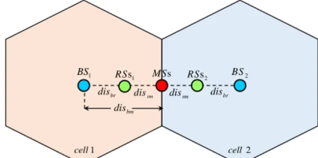
Fig. 4. Position of the nodes in a two-cell network. In each cell, there are two co-located cell-edge MSs, and corresponding to each MS, there are three co-located RSs.
Fig. 5. Comparison of the sum rate in a two-cell network with 𝐾 = 2, 𝐿 = 3, 𝑑 = 2 and for the first scenario. The path-loss exponent equals 3.5.
𝑑̂DFΣ = ∑ 𝐶
𝑐=1
∑
𝐾
𝑘=1
𝑑̂DF[𝑘,𝑐]
= ∑
𝑐=1 𝐶
∑
𝑘=1 𝐾
1
2[rank(𝐒𝐅
[𝑘,𝑐]) − rank(𝐉
𝐅
[𝑘,𝑐])]+
.
(28)
The proof is given in Appendix C.
IV. SIMULATION RESULTS
In this section, some numerical examples on the performance of the proposed schemes are presented. We also compare the proposed schemes with the IA-based noncooperative schemes in terms of the sum-rate and the sum DoF. In the noncooperative schemes, for the IA purposes, we consider the cellular min-leakage algorithm [16], the cellular orthogonalized max-SINR algorithm [16], and the closed-form IA solution [13].
A. General Assumptions
Throughout the simulations, it is assumed that
𝜎𝑛2= 1 and 𝑀𝑟> 𝑁𝑚,𝐅. In Figs. 5, 7, 9 and 12, the
path-loss exponent equals 3.5 and in Figs. 6, 8, 10 and 13, the path-loss exponent equals 5. In the figures, SNR is defined as𝑃𝑇/𝜎𝑛2, where 𝑃𝑇 denotes the power
allocated to each BS. Thus, the power allocated to each transmitted symbol is given as 𝑃(𝑖) =
br
dis
rm
dis
rm
dis
br
dis
1
BS RSs1 MSs RSs2 BS2
bm
dis
1
cell cell2
0 6 12 18 24 30 36 42 48 54 60
0 10 20 30 40 50 60 70 80 90
S
u
m
-r
at
e
(b
p
s/
H
z)
SNR (dB) Closed-Form IA Algorithm [13], (6×(4,2)2)2 Cellular M in-Leakage Algo., Iter. = 102, (6×(6,2)2)2 Cellular Or. M ax-SINR Algo., Iter. = 102, (6×(6,2)2)2 Proposed AF Scheme, (6×(4,2)2)2+(8×3,2)2×2 Proposed DF Scheme, (6×(4,2)2)2+(8×3,2)2×2
DoF
Sum=8
DoF
Sum=4
10𝑃𝑇(𝑖)/10/𝐾𝑑. It is also assumed that 𝑃 AF(𝑖) =
𝑃DF(𝑖) = 𝑃(𝑖)𝑑, 𝐶 = 2, 𝐾 = 2 and 𝐿 = 3. To have a
fair comparison with the noncooperative schemes, the total transmitted power by the BS and the RS in the relay-assisted schemes is assumed to be equal to the transmitted power by the BS in the noncooperative schemes.
Fig. 6. Comparison of the sum rate in a two-cell network with 𝐾 = 2, 𝐿 = 3, 𝑑 = 2 and for the first scenario. The path-loss exponent equals 5.
B.First Scenario
Let ℎ𝑖,𝑗 denote the channel coefficient from
terminal 𝑖 to terminal 𝑗 . It is assumed that
ℎ𝑖,𝑗~𝒞𝒩(0, 𝜎𝑖,𝑗2), where𝜎𝑖,𝑗2 is given by
𝜎𝑖,𝑗2 = (dis𝑖,𝑗/dis0) −𝛾
(29) where dis𝑖,𝑗 denotes the distance between terminals 𝑖
and 𝑗, dis0 is a fixed reference distance and 𝛾 is the
path-loss exponent. Let dis𝑏,MS[𝑘,𝑐], dis𝑏,RS[𝑟,𝑐] and dis[𝑟,𝑏][𝑘,𝑐]
denote the distance between the BS of cell 𝑏 and
MS[𝑘,𝑐]
, the distance between the BS of cell 𝑏 and
RS[𝑟,𝑐], and the distance between RS[𝑟,𝑏] and MS[𝑘,𝑐],
respectively. It is assumed that
𝑑𝑖𝑠𝑏,𝑀𝑆[𝑘,𝑐]= 𝑑𝑖𝑠𝑏𝑚= 5 𝑑𝑖𝑠0 ∀ 𝑘 ∈ 𝒦; 𝑏, 𝑐 ∈ 𝒞
𝑑𝑖𝑠𝑏,𝑅𝑆[𝑟,𝑐]= 𝑑𝑖𝑠𝑏𝑟 ∀ 𝑟 ∈ 𝒦; 𝑏, 𝑐 ∈ 𝒞
𝑑𝑖𝑠[𝑟,𝑏][𝑘,𝑐]= 𝑑𝑖𝑠𝑟𝑚 ∀ 𝑟, 𝑘 ∈ 𝒦; 𝑏, 𝑐 ∈ 𝒞
𝑑𝑖𝑠𝑏𝑚= 𝑑𝑖𝑠𝑏𝑟+ 𝑑𝑖𝑠𝑟𝑚.
(30)
Fig. 4 shows the network geometry under investigation. In this figure, it is assumed that dis𝑏𝑟=
0.75dis0 . Figs. 5 and 6 depict the sum rate
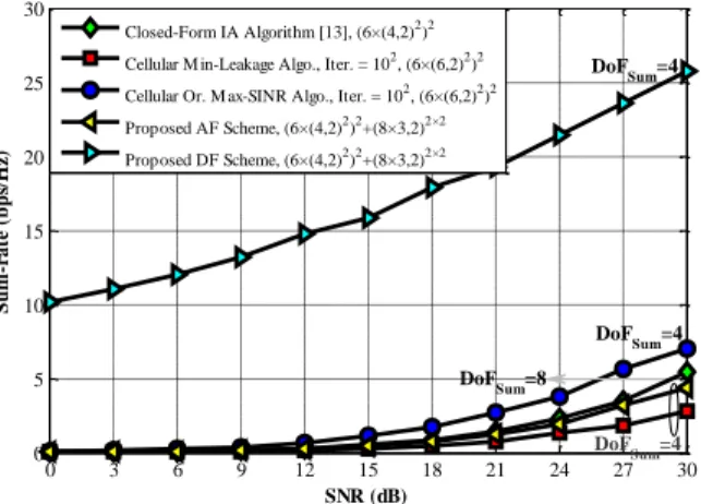
performance of the proposed schemes as a function of SNR under the above assumptions and for the case that 𝑑 = 2. The sum DoF corresponding to each scheme has been also shown in these figures. From Figs. 5 and 6, we observe that the AF scheme performs very close to the min-leakage algorithm over the entire range of SNR. We also observe that the DF scheme significantly outperforms both the min-leakage and max-SINR algorithms over the entire range of SNR. Also, the DF scheme outperforms the closed-form algorithm for the low and medium values of SNR. From Figs. 5 and 6, we also observe that the sum rate versus SNR curves in the AF and DF schemes and the iterative algorithms have the same slope in the high-SNR regime. This observation
implies that these schemes achieve the same sum DoF. This observation is in agreement with the DoF values shown in the figures.
Fig. 7. Sum rate of the proposed AF scheme for different number of transmitted data streams 𝑑 = 1, ⋯ ,4 in a two-cell system with 𝐾 = 2 and 𝐿 = 3. The path-loss exponent equals 3.5.
Fig. 8. Sum rate of the proposed AF scheme for different number of transmitted data streams 𝑑 = 1, ⋯ ,4 in a two-cell system with 𝐾 = 2 and 𝐿 = 3. The path-loss exponent equals 5.
As shown in Figs. 5 and 6, under perfect IA conditions, the sum DoFs in the closed-form IA solution [13] and the iterative algorithms are equal to
𝑑̂Σ= 𝐾𝐶𝑑̂ = 𝐾𝐶𝑑 = 8 and 𝑑̂Σ = 𝐾𝐶𝑑̂ = 1
2𝐾𝐶𝑑 = 4,
respectively. On the other hand, the maximum achievable DoF for the (𝑀𝑏× (𝑁𝑚,𝐇, 𝑑)𝐾)𝐶
MIMO-IFBC can be calculated as [4], [17]
𝑑Σ= min{𝐶𝑀𝑏, 𝐾𝐶𝑁𝑚,𝐇, max(𝑀𝑏, 𝐾𝑁𝑚,𝐇)}. (31)
Therefore, the algorithm in [13] and the iterative algorithms must achieve 𝑑Σ= 𝐾𝑁𝑚,𝐇= 8 and 𝑑Σ=
𝐾𝑁𝑚,𝐇= 𝐶𝑀𝑏= 12 under the configurations of (6 ×
(4,2)2)2 and (6 × (6,2)2)2, respectively. Also, under
perfect IA conditions, the first and second phases of the proposed schemes are able to achieve 𝑑̂Σ=
𝐾𝐶𝑑 = 8 degrees of freedom. The maximum achievable DoF for the first phase of the proposed schemes under the configuration of (6 × (4,2)2)2 can
be calculated as 𝑑Σ=
min{𝐶𝑀𝑏, 𝐾𝐶𝑁𝑟, max(𝑀𝑏, 𝐾𝑁𝑟)} = 𝐾𝑁𝑟= 8. On the
other hand, the maximum achievable DoF for the
(𝑀𝑟× 𝑁𝑚,𝐅, 𝑑) 𝐾×𝐶
𝐾 × 𝐶-user MIMO interference channel can be computed as [18]
0 6 12 18 24 30 36 42 48 54 60
0 10 20 30 40 50 60 70
S
u
m
-r
at
e
(b
p
s/
H
z)
SNR (dB) Closed-Form IA Algorithm [13], (6×(4,2)2)2 Cellular M in-Leakage Algo., Iter. = 102, (6×(6,2)2)2 Cellular Or. M ax-SINR Algo., Iter. = 102, (6×(6,2)2)2 Proposed AF Scheme, (6×(4,2)2)2+(8×3,2)2×2 Proposed DF Scheme, (6×(4,2)2)2+(8×3,2)2×2
DoF
Sum=4
DoF
Sum=8
DoF
Sum=4
0 10 20 30 40 50 60
0 10 20 30 40 50 60 70 80 90
S
u
m
-r
at
e
(b
p
s/
H
z)
SNR (dB) (3×(2,1)2)2+(5×2,1)2×2
(6×(4,2)2)2+(8×3,2)2×2 (9×(6,3)2)2+(12×5,3)2×2 (12×(8,4)2)2+(16×6,4)2×2
DoFSum=8
DoF
Sum=6
DoFSum=4
DoF
Sum=2
0 6 12 18 24 30 36 42 48 54 60
0 10 20 30 40 50 60 70
S
u
m
-r
at
e
(b
p
s/
H
z)
SNR (dB) (3×(2,1)2)2+(5×2,1)2×2
(6×(4,2)2)2+(8×3,2)2×2 (9×(6,3)2)2+(12×5,3)2×2
(12×(8,4)2)2+(16×6,4)2×2
DoF
Sum=6
DoF
Sum=8
DoFSum=2 DoFSum=4
Fig. 9. Sum rate of the proposed DF scheme for different number of transmitted data streams 𝑑 = 1, ⋯ ,4 in a two-cell system with 𝐾 = 2 and 𝐿 = 3. The path-loss exponent equals 3.5.
Fig. 10. Sum rate of the proposed DF scheme for different number of transmitted data streams 𝑑 = 1, ⋯ ,4 in a two-cell system with 𝐾 = 2 and 𝐿 = 3. The path-loss exponent equals 5.
𝑑Σ = {
min(𝑀𝑟, 𝑁𝑚,𝐅)𝐾𝐶, 𝐾𝐶 ≤ 𝑟
min(𝑀𝑟, 𝑁𝑚,𝐅)
𝑟
𝑟 + 1𝐾𝐶, 𝐾𝐶 > 𝑟
(32) where 𝑟 = ⌊max(𝑀𝑟, 𝑁𝑚,𝐅)/min(𝑀𝑟, 𝑁𝑚,𝐅)⌋ .
Accordingly, the maximum achievable DoF for the second phase of the proposed schemes under the configuration of (8 × 3,2)2×2 equals 𝑑
Σ=
𝐾𝐶min(𝑀𝑟, 𝑁𝑚,𝐅)𝑟/(𝑟 + 1) = 8. Based on the above
DoF analysis, among these schemes, the closed-form IA algorithm [13] and also the first and second phases of the AF and DF schemes can achieve the optimal DoF.
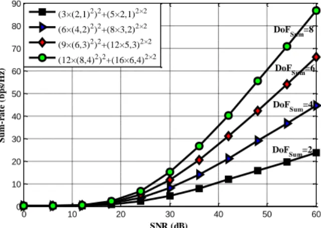
Figs. 7–10 illustrate the performance of the AF and DF schemes for different number of transmitted data streams in terms of the sum rate and the sum DoF. According to these figures, as the number of transmitted data streams increases, the sum DoF in the proposed schemes grows linearly. Thus, the sum rate of the proposed schemes is expected to increase linearly in the high-SNR regime.
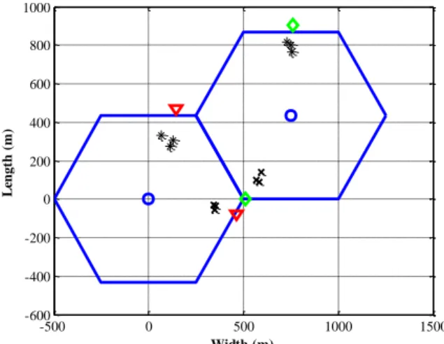
Fig. 11. Wrap-around-cell layout in a distributed two-cell network with radius 500m. In each cell, there are two cell-edge MSs, and corresponding to each MS, there are three RSs.
Fig. 12. Comparison of the sum rate performance in a two-cell system with 𝐾 = 2, 𝐿 = 3, 𝑑 = 2 and for the second scenario. The path-loss exponent equals 3.5.
C. Second Scenario
In this scenario, 𝜎𝑖,𝑗2 is chosen as [11]
𝜎𝑖,𝑗2 = 𝐴𝜓(dis𝑖,𝑗/dis0) −𝛾
(33) where 𝜓 is a random variable with variance 𝜎𝑆𝐹2
representing the log-normal shadowing and 𝐴 is an appropriate constant. We assume that 𝜎𝑆𝐹= 8 dB, and
the wrap-around-cell layout shown in Fig. 11 is considered for the network geometry. Figs. 12 and 13 compare the performance of the abovementioned schemes in terms of the sum rate and the sum DoF for the second scenario.
By comparing Figs. 5, 7, 9, 12 and Figs. 6, 8, 10, 13, we observe that as the path-loss exponent increases, the performance of all the schemes degrades. However, the proposed schemes exhibit a more robust behavior comparing to the noncooperative schemes.
0 6 12 18 24 30 36 42 48 54 60
0 20 40 60 80 100 120 140
S
u
m
-r
at
e
(b
p
s/
H
z)
SNR (dB) (3×(2,1)2)2+(5×2,1)2×2 (6×(4,2)2)2+(8×3,2)2×2
(9×(6,3)2)2+(12×5,3)2×2 (12×(8,4)2)2+(16×6,4)2×2
DoF
Sum=2
DoF
Sum=4
DoF
Sum=6
DoF
Sum=8
0 6 12 18 24 30 36 42 48 54 60
0 20 40 60 80 100 120 140
S
u
m
-r
at
e
(b
p
s/
H
z)
SNR (dB) (3×(2,1)2)2+(5×2,1)2×2 (6×(4,2)2)2+(8×3,2)2×2 (9×(6,3)2)2+(12×5,3)2×2
(12×(8,4)2)2+(16×6,4)2×2
DoF
Sum=8
DoF
Sum=6
DoF
Sum=4
DoF
Sum=2
-500 0 500 1000 1500
-600 -400 -200 0 200 400 600 800 1000
L
en
gt
h
(
m
)
Width (m)
0 3 6 9 12 15 18 21 24 27 30
0 10 20 30 40 50 60 70 80 90
S
u
m
-r
at
e
(b
p
s/
H
z)
SNR (dB) Closed-Form IA Algorithm [13], (6×(4,2)2)2 Cellular Min-Leakage Algo., Iter. = 102, (6×(6,2)2)2 Cellular Or. Max-SINR Algo., Iter. = 102, (6×(6,2)2)2 Proposed AF Scheme, (6×(4,2)2)2+(8×3,2)2×2 Proposed DF Scheme, (6×(4,2)2)2+(8×3,2)2×2
DoF
Sum=8
DoF
Sum=4
Fig. 13. Comparison of the sum rate performance in a two-cell system with 𝐾 = 2, 𝐿 = 3, 𝑑 = 2 and for the second scenario. The path-loss exponent equals 5.
V. CONCLUSION
In this paper, the spatial IA was investigated in the DL of a relay-assisted multi-cell multi-user network. The performance of this system was analyzed in terms of the sum rate and the sum DoF for the AF and DF relaying schemes. The simulation results showed that the DF scheme significantly outperforms the noncooperative min-leakage and max-SINR iterative algorithms over the entire range of SNR. Moreover, the DF scheme outperforms the noncooperative closed-form IA algorithm in the low and medium-SNR regimes. The DoF performance of the system also showed that the relay-assisted schemes can effectively eliminate the inter-cell and intra-cell types of interference.
APPENDIX A
CALCULATION OF (22)
Assuming i.i.d. Gaussian signaling, the achievable sum-rate for the AF scheme given in (22) can be rewritten as
𝑅AFΣ =
1
2∑
𝐶
𝑐=1
∑
𝐾
𝑘=1
∑
𝑑
𝑖=1
log2(1 + Ψ𝑖,AF
[𝑘,𝑐]) (34)
where Ψ𝑖,AF[𝑘,𝑐] is given by
Ψ𝑖,AF[𝑘,𝑐]= Ψ𝑖,𝐆
[𝑘,𝑐]
Ψ𝑖,𝐅[𝑘,𝑐]
1 + Ψ𝑖,𝐆[𝑘,𝑐]+ Ψ𝑖,𝐅[𝑘,𝑐] (35)
Ψ𝑖,𝐆[𝑘,𝑐] and Ψ𝑖,𝐅[𝑘,𝑐] are the SINRs of the 𝑖th received
stream corresponding to the first and second phases of the protocol, respectively. These two SINR values can be calculated as
Ψi,𝐆[k,c]= P|𝐮i,𝐆[k,c]H𝐆c [k,c]
𝐯i,𝐆[k,c]|2
÷ (σn2+ ∑ d
j=1,j≠i
P|𝐮i,𝐆[k,c]H𝐆c [k,c]
𝐯j,𝐆[k,c]|2
+ ∑
K
r=1,r≠k
∑
d
j=1
P|𝐮i,𝐆[k,c]H𝐆c[k,c]𝐯j,𝐆[r,c]|2
(36)
+ ∑
C
b=1,b≠c
∑
K
r=1
∑
d
j=1
P|𝐮i,𝐆[k,c]H𝐆b[k,c]𝐯j,𝐆[r,b]|2)
and the sum DoF for the AF and DF relaying
Ψ𝑖,𝐅[𝑘,𝑐]= 𝑃|𝐮𝑖,𝐅[𝑘,𝑐]𝐻𝐅[𝑘,𝑐][𝑘,𝑐]𝐯𝑖,𝐅[𝑘,𝑐]|2
÷ (𝜎𝑛2+ ∑ 𝑑
𝑗=1,𝑗≠𝑖
𝑃|𝐮𝑖,𝐅[𝑘,𝑐]𝐻𝐅[𝑘,𝑐][𝑘,𝑐]𝐯𝑗,𝐅[𝑘,𝑐]|2
+ ∑
𝐾
𝑟=1,𝑟≠𝑘
∑
𝑑
𝑗=1
𝑃|𝐮𝑖,𝐹[𝑘,𝑐]𝐻𝐅[𝑟,𝑐][𝑘,𝑐]𝐯𝑗,𝐅[𝑟,𝑐]|2
+ ∑
𝐶
𝑏=1,𝑏≠𝑐
∑
𝐾
𝑟=1
∑
𝑑
𝑗=1
𝑃|𝐮𝑖,𝐅[𝑘,𝑐]𝐻𝐅[𝑟,𝑏][𝑘,𝑐]𝐯𝑗,𝐅[𝑟,𝑏]|2)
(37)
where 𝐮𝑖,𝐆[𝑘,𝑐] and 𝐯𝑖,𝐆[𝑘,𝑐] are the 𝑖th columns of the matrices 𝐔𝐆[𝑘,𝑐] and 𝐕𝐆[𝑘,𝑐], and also 𝐮𝑖,𝐅[𝑘,𝑐] and 𝐯𝑖,𝐅[𝑘,𝑐] are the 𝑖th columns of the matrices 𝐔𝐅[𝑘,𝑐] and 𝐕𝐅[𝑘,𝑐], respectively. In the case of perfect IA, each phase of the relay-assisted multi-cell multi-user network is equivalent to the set of 𝐾 × 𝐶 independent MIMO links. In order to avoid inter-stream interference, it is necessary that each effective MIMO channel to be converted to parallel independent subchannels. Thus, in (34) to (37), 𝐕𝐆[𝑘,𝑐], 𝐔𝐆[𝑘,𝑐], 𝐕𝐅[𝑘,𝑐] and 𝐔𝐅[𝑘,𝑐] must be chosen as
𝐕𝐆[𝑘,𝑐]= 𝐕𝐆,IA[𝑘,𝑐]𝐕𝐆,SVD[𝑘,𝑐]
𝐔𝐆[𝑘,𝑐]= 𝐔𝐺,IA[𝑘,𝑐]𝐔𝐆,SVD[𝑘,𝑐] (38)
𝐕𝐅[𝑘,𝑐]= 𝐕𝐅,IA[𝑘,𝑐]𝐕𝐅,SVD[𝑘,𝑐]
𝐔𝐅[𝑘,𝑐]= 𝐔𝐅,IA[𝑘,𝑐]𝐔𝐅,SVD[𝑘,𝑐] (39)
where 𝐔𝐆,SVD[𝑘,𝑐] ∈ ℂ𝑑×𝑑 (𝐔 𝐅,SVD
[𝑘,𝑐] ∈ ℂ𝑑×𝑑) and 𝐕
𝐆,SVD
[𝑘,𝑐] ∈
ℂ𝑑×𝑑
(𝐕𝐅,SVD[𝑘,𝑐] ∈ ℂ𝑑×𝑑
) are the left and right singular matrices for the effective MIMO channel matrix
𝐔𝐆,IA[𝑘,𝑐]𝐻𝐆𝑐[𝑘,𝑐]𝐕𝐆,IA [𝑘,𝑐]
(𝐔𝐅,IA[𝑘,𝑐]𝐻𝐅[𝑘,𝑐][𝑘,𝑐]𝐕𝐅,IA[𝑘,𝑐]) which can be obtained using the singular value decomposition (SVD) as
𝐔𝐆,IA[𝑘,𝑐]𝐻𝐆𝑐[𝑘,𝑐]𝐕𝐆,IA
[𝑘,𝑐]= 𝐔
𝐆,SVD
[𝑘,𝑐] 𝚺
𝑐,𝐆
[𝑘,𝑐]𝐕
𝐆,SVD
[𝑘,𝑐]𝐻 (40)
𝐔𝐅,IA[𝑘,𝑐]𝐻𝐅[𝑘,𝑐][𝑘,𝑐]𝐕𝐅,IA[𝑘,𝑐]= 𝐔𝐅,SVD[𝑘,𝑐] 𝚺𝑐,𝐅[𝑘,𝑐]𝐕𝐅,SVD[𝑘,𝑐]𝐻 (41) where 𝚺𝑐,𝐆[𝑘,𝑐] (𝚺𝑐,𝐅[𝑘,𝑐]) is the singular value matrix for the effective MIMO channel matrix.
APPENDIX B
CALCULATION OF (26)
Similar to the AF scheme, by assuming i.i.d. Gaussian signaling, the achievable sum rate for the DF scheme given in (26) can be rewritten as
𝑅DFΣ =1
2∑
𝐶
𝑐=1
∑
𝐾
𝑘=1
∑
𝑑
𝑖=1
log2(1 + Ψ𝑖,DF
[𝑘,𝑐]) (42)
where Ψ𝑖,DF[𝑘,𝑐] is the SINR of the 𝑖th received stream corresponding to the second phase of the protocol.
0 3 6 9 12 15 18 21 24 27 30
0 5 10 15 20 25 30
SNR (dB)
S
u
m
-r
at
e
(b
p
s/
H
z)
Closed-Form IA Algorithm [13], (6×(4,2)2)2 Cellular M in-Leakage Algo., Iter. = 102, (6×(6,2)2)2 Cellular Or. M ax-SINR Algo., Iter. = 102, (6×(6,2)2)2 Proposed AF Scheme, (6×(4,2)2)2+(8×3,2)2×2 Proposed DF Scheme, (6×(4,2)2)2+(8×3,2)2×2
DoFSum=4
DoF
Sum=4
DoF Sum=4
DoF
Sum=8
This parameter can be computed as Ψ𝑖,𝐅[𝑘,𝑐] in (37). Similar to the AF case, for the DF scheme, the precodig and postcoding matrices can be obtained as (39) and (41).
APPENDIX C DERIVATION OF THE DOF
Substituting (26) into (27), the DoF at MS[𝑘,𝑐]
can be computed as [15]
𝑑̂DF[𝑘,𝑐]= lim
𝑃→∞
𝑅DF[𝑘,𝑐] log2(𝑃)
=1 2𝑃→∞lim{
1 log2(𝑃)
log2 det[𝐈𝑑+ (𝜎𝑛2𝐈𝑑
+𝐉𝐅[𝑘,𝑐]𝐉𝐅[𝑘,𝑐]𝐻)−1𝐒F[𝑘,𝑐]𝐒𝐅[𝑘,𝑐]𝐻]} =1
2[ lim𝑃→∞{
1 log2(𝑃)
log2 det[(𝜎𝑛2𝐈𝑑
+𝐉𝐅[𝑘,𝑐]𝐉𝐅[𝑘,𝑐]𝐻)−1𝐒𝐅[𝑘,𝑐]𝐒𝐅[𝑘,𝑐]𝐻]}]
+
=1 2[ lim𝑃→∞(
log2 det[𝐒𝐅
[𝑘,𝑐]𝐒
𝐅
[𝑘,𝑐]𝐻]
log2(𝑃)
−log2 det[𝜎𝑛
2𝐈
𝑑+ 𝐉𝐅
[𝑘,𝑐]𝐉 𝐅
[𝑘,𝑐]𝐻]
log2(𝑃)
)]
+
=1
2[ lim𝑃→∞( ∑rank(𝐒𝐅
[𝑘,𝑐])
𝑖=1 log2(𝜆𝑖(𝐒𝐅[𝑘,𝑐]𝐒𝐅[𝑘,𝑐]𝐻))
log2(𝑃)
−∑
rank(𝐉𝐅[𝑘,𝑐])
𝑖=1 log2(𝜆𝑖(𝐉𝐅
[𝑘,𝑐]
𝐉𝐅[𝑘,𝑐]𝐻) + 𝜎𝑛2)
log2(𝑃)
)]
+
=1 2[ lim𝑃→∞(
∑rank(𝐒𝐅[𝑘,𝑐])
𝑖=1 log2(𝐒𝐅,𝑖
[𝑘,𝑐]𝐒
𝐹,𝑖
[𝑘,𝑐]𝐻)
log2(𝑃)
−
∑rank(𝐉𝐅[𝑘,𝑐])
𝑖=1 log2(𝐉𝐅,𝑖
[𝑘,𝑐]𝐉 𝐅,𝑖
[𝑘,𝑐]𝐻+ 𝜎
𝑛2)
log2(𝑃)
)]
+
=1 2[ lim𝑃→∞(
∑rank(𝐒𝐅[𝑘,𝑐])
𝑖=1 log2(𝑃𝑐𝑖,𝐒)
log2(𝑃)
−∑
rank(𝐉𝐅[𝑘,𝑐])
𝑖=1 log2(𝑃𝑐𝑖,𝐉+ 𝜎𝑛2)
log2(𝑃)
)]
+
=1 2[ lim𝑃→∞(
∑rank(𝐒𝐅[𝑘,𝑐])
𝑖=1 log2(𝑃)
log2(𝑃)
−∑
rank(𝐉𝐅[𝑘,𝑐])
𝑖=1 log2(𝑃)
log2(𝑃)
)]
+
=1
2[rank(𝐒𝐅
[𝑘,𝑐]) − rank(𝐉
𝐅
[𝑘,𝑐])]+
where 𝐒𝐅,𝑖[𝑘,𝑐] and 𝐉𝐅,𝑖[𝑘,𝑐] are the 𝑖th rows of 𝐒𝐅[𝑘,𝑐] and
𝐉𝐅[𝑘,𝑐], respectively. Also 𝑐𝑖,𝐒 and 𝑐𝑖,𝐉 are two constant
values, where 0 < 𝑐𝑖,𝐒≪ +∞ and 0 < 𝑐𝑖,𝐉≪ +∞.
REFERENCES
[1] C. Suh, M. Ho, and D. N. C. Tse, “Downlink interference alignment,” IEEE Trans. Commun., vol. 59, no. 9, pp. 2616– 2626, Sep. 2011.
[2] K. T. Truong, P. Sartori, and R. W. Heath, “Cooperative algorithms for MIMO amplify-and-forward relay networks,”
IEEE Trans. Signal Process., vol. 61, no. 5, pp. 1272–1287, Mar. 2013.
[3] V. Cadambe and S. Jafar, “Interference alignment and degrees of freedom of the 𝐾-user interference channel,” IEEE Trans. Inf. Theory,vol. 54, no. 8, pp. 3425–3441, Aug. 2008. [4] W. Shin, N. Lee, J.-B. Lim, C. Shin, and K. Jang, “On the
design of interference alignment scheme for two-cell MIMO interfering broadcast channels,” IEEE Trans. Wirel. Commun., vol. 10, no. 2, pp. 437–442, Feb. 2011.
[5] K. T. K. Cheung and L. Hanzo, “Distributed energy spectral efficiency optimization for partial/full interference alignment in multi-user multi-relay multi-cell MIMO systems,” IEEE Trans. Signal Process., vol. 64, no. 4, pp. 882–896, Feb. 2016.
[6] A. S. Zamzam, A. El-Keyi, M. Nafie, and Y. Mohasseb, “On the degrees of freedom of the two-cell two-hop MIMO network with dedicated and shared relays,” IEEE Trans. Wirel. Commun., vol. 14, no. 12, pp. 6738–6751, Dec. 2015. [7] X. Li, H. Al-Shatri, R. S. Ganesan, D. Papsdorf, A. Klein, and
T. Weber, “Uplink-downlink duality of interference alignment in cellular relay networks,” in Proc. 10th Int. ITG Conf. on Systems, Commun. and Coding, Hamburg, Germany, Feb. 2015, pp. 1–6.
[8] X. Wang, Y. P. Zhang, P. Zhang, X. Ren, “Relay-aided interference alignment for MIMO cellular networks,” in Proc. Int. Symp. on Inf. Theory (ISIT), Cambridge, MA, USA, July 2012, pp. 2641–2645.
[9] C. D. T. Thai, J. Lee, H. X. Nguyen, M. Berbineau, and T. Q. S. Quek, “Multi-cell multi-user relaying exploiting overheard signals,” IEEE Wirel. Commun. Lett., vol. 3, no. 4, pp. 401– 404, Aug. 2014.
[10] Y. Shu, Q. Wang, J. Zhang, and T. Sun, “Relay-aided interference alignment and neutralization for 3-cellular interference channels,” in Proc. IEEE/CIC Int. Conf. on Commun. in China (ICCC), Shanghai, China, Oct. 2014, pp. 637–641.
[11] D. A. Basnayaka and H. Haas, “Overcoming large-scale fading in cellular systems with network coordination,” IEEE Trans. Commun., vol. 62, no. 7, pp. 2589–2601, Jul. 2014. [12] Q. F. Zhou, F. C. M. Lau, and S. F. Hau, “Asymptotic
analysis of opportunistic relaying protocols,” IEEE Trans. Wirel. Commun., vol. 8, no. 8, pp. 3915–3920, Aug. 2009. [13] J. Tang and S. Lambotharan, “Interference alignment
techniques for MIMO multi-cell interfering broadcast channels,” IEEE Trans. Commun., vol. 61, no. 1, pp. 164– 175, Jan. 2013.
[14] S. Liu, Y. Du, “A general closed-form solution to achieve interference alignment along spatial domain,” in Proc. IEEE Global Commun. Conf. (GLOBECOM), Miami, USA, Dec. 2010, pp. 1–5.
[15] D. S. Papailiopoulos and A. G. Dimakis, “Interference alignment as a Rank constrained rank minimization,” IEEE Trans. Signal Process., vol. 60, no. 8, pp. 4278–4288, Aug. 2012.
[16] B. Zhuang, R. A. Berry, and M. L. Honig, “Interference alignment in MIMO cellular networks,” in Proc. IEEE ICASSP, Prague, Czech Republic, May 2011, pp. 3356–3359. [17] S. A. Jafar, M. J. Fakhereddin, “Degrees of Freedom for the
MIMO Interference Channel,” IEEE Trans. Inf. Theory, vol. 35, no. 7, pp. 2637–2642, July 2007.
[18] T. Gou and S. A. Jafar, “Degrees of Freedom of the 𝐾-User
𝑀 × 𝑁 MIMO Interference Channel”, IEEE Trans. Inf.
Theory, vol. 56, no. 12, pp. 6040–6057, Dec. 2010.
Ali Golestani received his B.Sc. degree in electrical engineering from IHU, Tehran, Iran, in 2012 and the M.Sc. degree in electrical engineering from K. N. Toosi University of Technology, Tehran, Iran, in 2015. His research interests include cooperative communications, interference alignment (IA) technique, and new generation cellular networks technologies.
Ali H. Bastami received his
B.Sc. degree in electrical engineering from the University of Science and Technology, Tehran, Iran, in 2003, the M.Sc. degree (with highest honors) in electrical engineering from Amir-Kabir University of Technology, Tehran, Iran, in 2006, and the Ph.D. degree in electrical engineering from the University of Tehran, Tehran, Iran, in 2011. Since 2012, he has been an Assistant Professor at the Department of Electrical and Computer Engineering, K. N. Toosi University of Technology, Tehran, Iran. He received the best thesis award from the Department of Electrical and Computer Engineering, University of Tehran, in 2011. His research interests include cooperative communications, cognitive radio networks and multiple-input multiple-output (MIMO) communication systems.
K. Mohamed-pour was born in
1954, and received his B.Sc. and M.Sc. degrees in Electrical Engineering-Telecommunication in Tehran, 1979 and 1987 respectively. After some lecturing in Communication department in Electrical Engineering Faculty of K.N.Toosi University of Technology, continued his studying towards Ph.D. in University of Manchester, U.K. 1995.Dr. Mohamed-pour is a full professor at K.N.Toosi University and has published several books in Digital Signal Processing and Digital Communications. His main research interests are Broadband Wireless Communications, MIMO-OFDM, and Communication Networks.