4069
INTERNET OF THINGS (IoT) MOBILITY SUPPORT BASED
ON DISTRIBUTED SENSOR PROXY MIPV6
1JABIRY M.MOHAMMED, 1BI-LYNN ONG, 1,2R. BADLISHAH AHMAD, 1MOHAMMED HAKAWATI
1School of Computer and Communication Engineering, University Malaysia Perlis (UniMAP)
2Faculty of Informatics and Computing, University Sultan Zainal Abidin (UniSZA)
[email protected], [email protected], [email protected],[email protected]
ABSTRACT
It is expected that the footprint of the Internet of Things (IoT) will increase in the future. In order for this increase to occur, a network architecture which is flexible and capable of handling multiple flows with varying requirements as well as dynamically meeting the current demands. A new era of dynamic entities (nodes) within an environment like smart hospitals and cities is being empowered by IoT. The Sensor Proxy Mobile IPv6 (SPMIPv6) has been specifically determined for IP-based wireless sensor network (WSN) mobility with the aim of potentially reducing the consumption of energy by means of preserving the mobile nodes from being part of the handoff process. The majority of the shortcomings of the Proxy Mobile IPv6 (PMIPv6) such as non-optimized communication path, long handoff latency, and bottleneck issues were inherited by SPMIPV6. An improved SPMIPv6 architecture called Distributed SPMIPv6 (DSPMIPv6) is presented in this work with the aim of addressing the aforementioned problems. The solution proffered in the present architecture includes de-coupling the entities that are part of the control and data planes; the Dynamic Mobility Access Gateway (MAG) located close to the edge of the network distributes and manages the data plane, while the control plane, is dependent on a central entity called Sensor Local Mobility Anchor (SLMA). The introduced design is evaluated analytically, and the numerical results show that the performance of the DSPMIPv6 design is better than that of both SPMIPv6 and PMIPv6 protocols in terms of Local Mobility Anchor (LMA) load, and transmission cost performance metrics.
Keywords: Distributed mobility management, Mobility management, IP-WSN, Handover mechanism, PMIPv6, Serving DMAG (S-DMAG), Previous DMAG (P-DMAG)
1. INTRODUCTION
Due to the wide range of commercial applications such as industrial automation, smart home automation, and healthcare, IoT has become very important. A wireless sensor network (WSNs) is made up of many small devices which have the ability to identify and get information from the immediate environment. The emergence of IoT era, the IP-WSN protocol has emanated to help in the compatibility of sensors with IP solution [1]. The interconnection of WSNs with other networks, capitalization of the existing Internet infrastructure and cohesive connection of IP-applications with sensor networks, can be facilitated by Integrating the Internet Protocol (IP) [2].
When the WSNs limitations and advantages of an IP-enabled architecture are taken into account, lightweight protocol becomes an important
4070 Because of the growing interest and research in the area of IoT, mobility management protocols have become very important in the present environment, the static characteristics of nodes no longer dominate. Full access to information should be provided by mobility management protocols for users regardless of the location of users. Nodes can locally move within a domain or outside the domain. In addressing of mobile networks and mobility management demand of mobile nodes (MNs), The IETF has systematized the host-based Mobile IPv6 (MIPv6) [4] and Network Mobility (NEMO) [5] protocols. The continuity of the communication session host is assisted by both protocols during handover. Nevertheless, long HO latency, high signaling overhead, and high packet loss ratio are some of the challenges faced by the host-based protocols [6]. To tackle problems related to host- based protocols, the IETF has standardized the Proxy Mobile IPv6 (PMIPv6) [7]Two functional entities are added by the PMIPv6 which are; Local Mobility Anchor (LMA) and Mobility Access Gateway (MAG). LMA is concerned with movement within the PMIPv6 domain; it helps to keep the MN prefix reachable while it moves within the local PMIPv6 domain. The MAG discovers MN movements and establishes the needed authentication signals with the Authentication, Authorization, and Accounting (AAA) server to register the MN with LMA. To achieve registration, the MAG needs the network prefix of the MN, the LMA address, and the allowed address configuration modes. The AAA server stores all these information in either a centralized or distributed manner [8].
This paper gives an improved architecture of SPMIPv6, known as Distributed-based SPMIPv6 (DSPMIPV6), into tackle bottlenecks, route optimization problems and long handoff latency problems. The study will contribute in the following ways:
(a) The study will provide a comprehensive preview and analysis of the many approaches used to connect WSN to the Internet. Then, it will analyze the way the mobility protocols have developed to position themselves for WSN.
(b) Identification of the disadvantages of SPMIPv6, which is the motivation behind this proposed architecture.
(c) Came up with a new architecture called DSMIPv6 protocol.
(d) Efficiency evaluation of the proposed DSPMIPv6 architecture by presenting the mathematical analysis and respective numerical results.
2. RELATED WORK
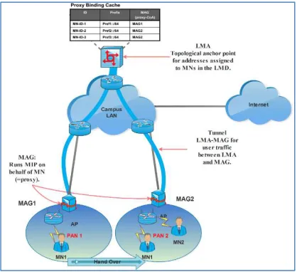
[image:2.612.314.523.222.413.2]To solve problems related to host-based MIPv6 and NEMO protocols, it is best to select PMIPv6 as network-based mobility protocols to reduce signaling and mobility costs. PMIPv6 helps to meet the demands of energy efficiency due to it prevents the MN from taking part in any mobility signaling as presented in Figure 1.
Figure 1: PMIPv6 architecture
4071
2.1 Disadvantages of the SPMIPv6
Even though there are certain benefits of introducing the SPMIPv6 to WSNs, some disadvantages still exist which were inherited from PMIPv6 which are:
(a) Bottleneck: to keep its binding information, the Local Mobile Anchor in PMIPv6 keeps a Binding Cash Entry for each MN and this BCE should be updated detach MN movement. Additionally, the LMA should process every data packet belongs to MN and controls all the mobility signaling messages. There will be a significant increase in the load of the LMA as a result of this extensive access which will eventually lead to a bottleneck in LMA [12].
(b) Handoff Latency: The MN suffer from long HO delay due to all handoff related messages should pass through the LMA, whose current location counted a long way from the MAGs. Additionally, HO procedure consists of acquiring the AAA server permission for authentication; therefore, the communication signaling of performing the MN is increased [12].
(c) Route Optimization: All routes among CN and MN pass via the LMA in PMIPv6, although if the MN and CN together are located in the same PMIPv6 domain, which leads to a non-optimized path between CN and MN [12].
(d) Load Balancing: on behalf of the MNs, the For CMM approach architecture the MAGs function are exchanged mobility-related signaling with LMA.However, because the load balancing strategy is absent, when many MNs are attached to MAGs, it can be overloaded [13].
The IP-based mobility management protocols that already exist such as the network-based PMIPv6 and the host-based MIPv6 are positioned in a CMM scheme where all the data traffic and mobility signaling go through a centralized entity point to manage the bindings and reachability of the MN [7,14]. To conquer the downside and challenges of the CMM by dissociating the control and data planes, a number of other works have been proposed. These problems have been recognized by IETF, a group in charge of standardization of these protocols, and this group recently developed a novel distributed mobility management (DMM) solution [15, 16]. The DMM paradigm is made up of a flatter architecture that distributes the control and data planes by beginning equipped the edge router with some mobility function closer to the MN. The DMM can be generally divided into two approaches: partially distributed mobility management (P-DMM), the control plane is kept central and only the
data plane is distributed and fully distributed mobility management (F-DMM), whereby both the data and control planes are distributed [17].
This section presents past studies that are related to studies on the network- based DMM schemes. CMM and DMM were compared, problems that can be investigated were presented and DMM scheme
Another solution is described in [18] Proposed F-DMM using IP prefix information to control the mapping between the identifier and the locator. The same prefix is advertised by the MAGs in this scheme while the duties of the LMA are distributed on all access routers and each MN gets its address using a stateful address configuration. However, tight control of IP addressing is needed in this approach. The authors of [19] examined the performance of dynamic mobility activation and distributed mobility anchoring and compared it with the simulations of PMIPv6. Going further, another development presented in [20] gives a comprehensive assessment of the performance of distributed and dynamic mobility management (DDMM) compared with MIPv6, localized routing PMIPv6, and PMIPv6. The results revealed that in terms of packet delivery, throughput cost and tunneling, the DDMM provides a higher performance. Qualitative and quantitative analyzes of distributed MIPv6 and PMIPv6 compared with existing protocols are presented by the writers of [21]. A comparative performance analysis on dynamic mobility anchoring (DMA) and PMIPv6, where the DMA outperforms PMIPv6 significantly is presented by the same authors.
3. PROPOSED DSPMIPV6 APPROACH
4072 AAA into the DMAG. The interesting solution is described in [9] inspired by the idea of reducing signaling overhead by merging the AAA with LMA. However, the central point of the breakdown was extended to imply binding and authentication information together. For the earlier reason, the DMAG possesses features that anchor mobility functions thereby having the capability of forwarding without interfering with the IP flows which an MN started while connected to it prior to attaching to the new DMAG.
Figure 2:Dspmipv6 Architecture.
DSPMIPv6 architecture is made up of an SLMA, DMAGs and numerous MNs, as shown in Figure 2. The DMAG which is equipped with mobility anchoring functions replaces the MAG role and serves as a plain access, which provides no tunneling to forward packets to and from the Internet. The evolution of DMAG occurs when the DMAG is provided with links to the Internet that do not imply paths cutting across the LMA. This makes the DMAG able to forward IP payload flows started by MN without delay or drop interference while moving to a new DMAG. Additionally, the SLMA job has been a relief to a control plane entity only.
In order to carry out the handoff, registration and communication process in DSPMIPv6, there should be an exchange of numerous messages among the DSPMIPv6 entities. Such messages which should be
exchanged include Proxy Binding
Acknowledgement (PBA), Proxy Binding Update (PBU), Distributed PBU (DPBU) and Distributed PBA (DPBA). Furthermore, the different binding list of all the DMAGs and SLMA should be maintained properly so that the information which is required for the MNs current location can be stored. MNs are
[image:4.612.314.517.138.363.2]registered with SLMA using the PBU and PBA in the same way as the PMIPv6; a comprehensive description of PBU and PBA is described in [22].
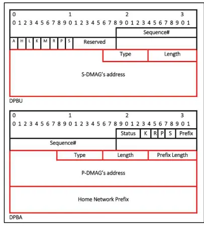
[image:4.612.92.299.230.419.2]Figure 3: Messages And Mobility Options.
Figure. 3 presents novel messages and mobility options. The use of two news mobility options which are the previous DMAG Option and current Serving DMAG Option is employed in differentiating the messages which are exchanged. The control messages exchanged between SLMA and DMAG PBA has been equipped with our proposed Previous DMAG new option. The S-DMAG is notified about the previous DMAG’s global address as well as the prefix anchored to it through this option. On the other hand, the PBU and PBA control's messages exchanged between the SLMA, and a P-DMAG are equipped with the new serving DMAG option, providing necessary information to the P-DMAG about the current global address of S-DMAG.
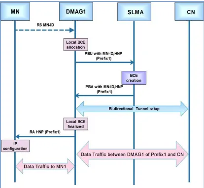
3.1 Registration
4073 fields are stored by the SLMA. The SLMA replies to DMAG1 which possesses a PBA comprising the conventional options defined in [7] is replied by the SLMA. This implies that there is no available status so MN’s registration is new.
Figure 4: Registration Signaling
The temporal BCE which was previously allocated is stored by the DMAG1 and an RA message with MN prefix is unicast to the MN which was previously preserved and will be employed by the MN for configuring a stateless IPv6 address through the use of an auto-configuration approach. It is possible to re-route the address at the DMAGI because it is located on the path of packets addressed to the MN. Again, due to the fact that there is no special handling or encapsulation that occurs, the DMAG1serves as a plain router for those packets as seen in figure 4.
3.2 Handoff
The dynamic functionality of DMAG is implemented through reserved a new IPv6 prefix to the MN after MN moves from current access and connects with DMAG2 which is now S-DMAG. Also, a temporal BCE is stored by the DAMG2 and a plain PBU is sent to the SLAM for registration. A pre-existing entry for the MN is retrieved by SLMA upon BC lookup and PBU reception thereby joining the MN-ID to its previous location. Therefore, the DPBU indicated as proxy-CoA is forwarded to the DMAG1 by SLMA as well as a new mobility option to inform the DMAG1 about the S-DMAG’s global address which is regarded as serving DMAG Option. The P-CoA field within the BCE associated with the DMAG2’s address is updated by the SLMA. When
[image:5.612.91.298.162.353.2]PBU is received, a tunnel can be installed by DMAG1 in the direction of DMAG2 serving Pref1 flows.
Figure 5: Dspipv6 Handoff Signaling
At this point, the DMAG1 becomes aware of the new MN’s location which is DMAG2 due to the S-DMAG’s address within the S-DMAG option. In addition to sending a DPBA to the SLMA, a PBA is also sent by DMAG1 to the DMAG2 including the prefix which it anchors. The prefix is incorporated into the HNP while the DMAG1’s address is taken from the source address of the message with no new options added. A copy is directly received from the DMAG1 with important information which will be used in building the tunnels and setting up the right routes while the SLMA is released from passing the PBA toward DMAG2 as shown in figure 5.First of all, the packets which are sent to Pref1 are received by DMAG1 and then encapsulated in the bio-directional path to DMAG2, It then eventually directs data flows destined to MN. In uplink, the MN who still reserve Prefix1 and attached to DMAG2 want to send data flow, these data must send to Serving DMAG (DMAG2). Afterward, the packets are tunneled to DMAG1 which sends them to the next destination. On the other hand, DMAG2 routes the packets bearing Pref2 and both downlink and uplink are not handled by any special packet.
3.3 De-registration
4074 the SLAM are removed by the DMAG because the MN is no longer present on the access link of the DMAG; any continuity attempt made by prefix is destroyed through this process. In order to overcome this shortcoming, the serving DMAG can be allowed to de-register the entire MN session rather than the previous DMAG. This can be achieved by first of all using MIH technique to remove any form of layer-2 detachment event in order to stimulate de-registration when the lifetime of the session expires thereby providing a guard interval which will allow the connection between the MN and the new DMAG. Subsequently, the BCE timer is stopped by a previous DMAG once a PBU is received from the SLAM which contains a “serving DMAG” option. This way, the mobility session can only be de-registered by the serving DMAG, arguing that the MN left definitely the domain.
4. PERFORMANCE EVALUATION 4.1 System Environment Design
A network mobility scheme is proposed by deploying several MNs throughout the network. A network domain consisting of a number of identical circular low-powered, short-distance wireless network cell called personal area network (PAN); each PAN in the CMM or DMAG approach should be served by one MAG or DMAG respectively. Moreover, each cell is equipped with an access Point near the MAG or DMAG given the MNs wireless link accessibility. It is assumed that the radius of each cell is R and that the area, A, of each cell is given by A = π. R2.
The hop distance (average number of hops) between two network entities x and y is referred to as Tx-y, which is hypothetical to be symmetrical; that is, Tx-y = Ty-x. Additionally, in the CMM we presume that the hop distance among the MAG and LMA is equal to the hop distance among the DMAG and the SLMA in the P-DMM. Based on certain variation among the wireless and wired communication links need to be defined, the unit transmission cost within wired link is denoted by τ while the unit transmission cost within the wireless link is represented by κ. For performance analysis simplicity the average hop distance among two entities like MNs/CNs on one side and the MAG in CMM or the DMAG in DMM is considered equal.
4.2 Mobility model
In this study, it is assumed that the handover (HO) takes place at the time that the MN moves from one PAN to another and therefore the PAN crossing
rate µc is equivalent to the HO rate. Also, we supposed that the residency time of the MN in the PAN is a random variable which is exponentially distributed with mean value 1/µc and a fluid flow model is considered for the MN movement. The direction of the MN, activity is regularly dispensed over the range [0, 2π] with an average velocity of V [20]. Afterward, the PAN crossing rate to be formulated as:
μ = 2. √ . =
2.
. (1)
4.3 Traffic model
Considering the fact that an MN has several active sessions along with different CNs at the same time among DMM approach, we presume that the session arrival at an MN follows a Poisson process with mean rate λs and that the duration of a typical session is exponentially distributed with mean rate ls. The system is modeled under the probability distribution of the M=M=1 queue, the average number of active sessions at a time is λs /µc [21, 23]. A dedicated prefix from one of the DMAGs is possessed by each active session and each prefix is tied to a given CN. The average number of CNs at any a specific town is denoted by ɲcn, which is also the average number of active prefixes; hence ɲcn is given by:
= (2)
Furthermore, we presume after the determined time of HO operation, the MNs will terminate some active session with CNs causes a few of neglected prefixes. Therefore, the average number of CN’s which need a process of de-registration to unleash the prefixes attached to these CNs is denoted by δcn. Distinguishing the new traffic to the PAN and HO traffic from the other PAN is crucial in analyzing the mobility management schemes performance. Thus, the arrival rate of total traffic is considered as λT, in
the PAN as λT = λn + λh; λn as the new traffic arrival
mean rate, and λh represents the HO traffic arrival
mean rate. Then the possibility that a traffic is a new traffic is formulated as Pn = λn/λT while the
probability that a traffic is an HO traffic is Pn = λh /
λT. Assuming that the mean value of average HO for
a session is denoted by E(N) and N denotes the number of HO in a session. Then, the HO traffic arrival mean rate can be expressed by λh = λnE(N).
4075 ( ) = (3)
As a result, we get λh = λn (µc/µs) and hence the
probability of new and handover traffic [23]:
= + (4)
ℎ = 1 − = + (5)
5. TOTAL COST ANALYZING
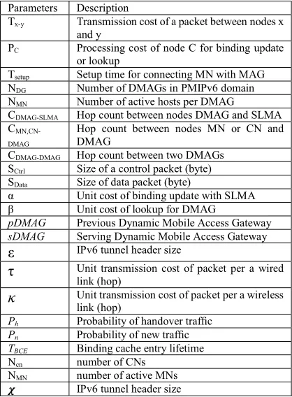
[image:7.612.90.299.371.655.2]The superiority of the newly proposed DSPMIPv6 is shown in this section by analyzing how efficient it is in solving the problems of PMIPv6 such as handoff latency, LMA bottleneck, and route optimization. For future work. Table 1 shows the notations of performance used by Jung et al., [25] alongside new
Table 1
:
The notations of performanceParameters Description
Tx-y Transmission cost of a packet between nodes x and y
PC Processing cost of node C for binding update or lookup
Tsetup Setup time for connecting MN with MAG
NDG Number of DMAGs in PMIPv6 domain
NMN Number of active hosts per DMAG
CDMAG-SLMA Hop count between nodes DMAG and SLMA C
MN,CN-DMAG
Hop count between nodes MN or CN and DMAG
CDMAG-DMAG Hop count between two DMAGs SCtrl Size of a control packet (byte) SData Size of data packet (byte)
α Unit cost of binding update with SLMA
β Unit cost of lookup for DMAG
pDMAG Previous Dynamic Mobile Access Gateway
sDMAG Serving Dynamic Mobile Access Gateway
ε
IPv6 tunnel header sizeτ
Unit transmission cost of packet per a wired link (hop)κ
Unit transmission cost of packet per a wireless link (hop)Ph Probability of handover traffic
Pn Probability of new traffic
TBCE Binding cache entry lifetime
Ncn number of CNs
NMN number of active MNs IPv6 tunnel header size
Notations which were added for the analysis of the proposed DSPMIPv6.
In this article, various possible movement scenarios are available, for simplify the performance
analysis we will only consider the inter-domain movement mode.
5.1 Cost Analysis
Adopting the model presented in [25] with some modifications made, to enrich it with appropriate hypothesize for introducing DSPMIPv6 design. The total cost (TC) is derived. Both the distance between DMAGs and their attached MNs as well as the cost of authentication were considered when the modifications were made. The TC is computed as the combination of the Binding Update Cost (BUC) and the Packet Delivery Cost (PDC).
5.1.1 PMIPv6
In conventional Proxy Mobile IPv6 network-based mobility; the process of BU imply connection setup among the MN and MAG which requires TSetup, authenticating the MN which requires 2TMAG-AAA +2TLMA-AAA. [26] The control messages
PBU and PBA Interchange along with the LMA which requires 2TMAG-LMA + PLMA. Therefore, the
BUC can be presented as:
BUC = T +
× . (2T + 2T
+ 2T ) + P = T +
× . (2 C + 2τC
+ 2τC ) + αlog( × )
(6)
In PMIPv6, the process of packet delivery starts by sending the packet from MN to its LMA through MAG which requires TMN-MAG + TMAG-LMA. The
CN’s address (PLMA), is searched for in the binding
cache of LMA by the LMA and afterward the packet is sent to the destination MAG (TMAG-LMA). The
Destination MAG (TMAG-LMA) then forwards the
packet to the CN (TMAG-CN). The PDC can be derived
as follows:
= × (T
+ 2T
+ T ) + P
4076 = × (κC
+ 2κC
+ κC )
+ βlog( × )
Hence, the Proxy MIPv6 Total cost can be computed as:
TCPMIP =BUCPMIP +PDCPMIP (8)
5.1.2. SPMIPv6
In Sensor Proxy Mobile IPv6, the LMA has been enriched by the authentication mission, by combining control messages PBU and AAA query as well as the PBA and AAA reply messages in order minimize the communication signaling [6]. Along with the LMA cost of processing for authentications and processing actions together (2PLMA) is doubled
by this technique. The process of BU establishes connection setup among MN and MAG that needed TSetup and the exchange of the combined authentication and binding message which requires SCtrl × 2TMAG-LMA.
BUC = T + S
× ζ . (2 )
+ 2P = T + S
× ζ . (2 )
+ 2 αlog( × )
(9)
Sensor Proxy Mobile IPv6 and Proxy Mobile IPv6 both follow the same PDC procedure.
PDCSPMIP =PDCPMIP (10)
Therefore, the following assumption can be used in calculating TC of SPMIPv6:
TCSPMIP =BUCSPMIP +PDCSPMIP (11)
5.1.3 DSPMIPv6
To illustrate the new approach, the MN change his point of attachment from DMAG to another among SLAM domain. The DMAG handling cost is also has been duplicate due to the DMAG carry outs the authentication and registration functions together (2PDMAG).To accomplish MN location update operation, the serving DMAG and the previous DMAG need to exchanging signaling messages with SLMA (TsDMAG-SLMA+2TSLMA-pDMAG+TpDMAG-sDMAG),
led to the implication of the SLMA entity in HO
procedure to update BCE table. Thus the MN location update drove along with BUC update the following equation is obtained The Packet Delivery Cost is initiated as follows:
BUC = T + S × ζ . . T
+ 2T + T
+ 2P + P = T + S × ζ . . τC
+ 2τC + τC
+ αlog( × ) + 2 αlog( × ) (12)
The communication between two MNs that belong to different DMAGs share the same DSPIPv6 domain follow by two scenarios. First, the communication between MN and CN is performed directly as follows: Once S-DMAG receives a packet from the MN (TMN-sDMAG), it forwards the packet to
the CN’s DMAG, the data can be sent to the CN which requires (TsDMAG-CN). The second scenario
performed indirectly, the MN sent a packet to S-DMAG (TMN-sDMAG) the S-DMAG communicate
with the P-DMAG (TsDMAG-pDMAG) then the
P-DMAG deliver the data to CN. Accordingly, the PDC for the DSPMIPv6 can be expressed as follows:
= . T + T +
. 2T + P
= . κC + κC )
+ . 2 χ + ( ) C
+2βlog( × )
Accordingly, the following can be used in calculating TC of DSPMIPv6:
(13)
TCDSPMIP=BUCDSPMIP+PDCDSPMIP (14)
5.3 SLMA Load
4077 Obtaining the processing capability of LMA into attention, the threshold θ indicates the highest approved load on LMA. On the condition that p > θ, LMA becomes burdened, the packets will suffer a prolonged queuing delay which led to high end- to-end delay and the packet loss ratio [13]. In our new design, the LMA load is mitigated by relieving the LMA functionality from the data forwarding and preserved it only for control operations. The number of LMA involvement in processing cost and control accesses operation will determine the LMA load. As shown in equation (6), the LMA has been accessed four times and counted PLMA for BU request operation. Equation (7) reveals that the LMA is accessed twice and obtains PLMA to carry out the communication procedure. Hence the LMA load in the PMIPv6 domain can be declared as:
= (6 + 2 ) (15)
Following the location updates and communication processes the where N refers to the MNs in PMIPv6 domain. Applying this assumption, the SPMIPv6 and DSPMIPv6 domains LMA load can be declared by obtaining Equations (9)-(10) and (12)-(13), respectively, i.e.,
= (4 + 3 ) (16)
= (3 + ) (17)
6. NUMERICAL RESULTS
[image:9.612.310.522.288.456.2]In this section numerical results are presented based on the derivations in the previous section. In order to ensure a level comparative platform, the use of the assumptions and parameter values in [25] were used in this study as presented in Table 2.
Table 2 Parameter values.
Parameters Values
PC 12
Tsetup 500 (ms)
NDG 20
NHM 200
CDMAG-SLMA 12
CMN,CN-DMAG 1
CDMAG-DMAG 6
SCtrl 50 (bytes)
SData 1024 (bytes)
α 3
β 2
ε 40 (bytes)
τ 2
κ 4
δcn 2
2 50 (bytes)
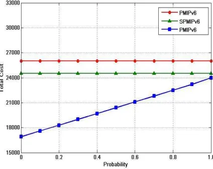
The effect of Distributed operations on the TC by changing the parameter (p) and setting all other parameters to their default values is shown in Figure 6. Since the same signals and operations are carried out for both inter-and intra-operations, which involves gaining access to the LMA, the TC is positioned in the PMIPv6 and SPMIPv6. On the other hand, the packet is processed by the DSPMIPv6 using two methods according to the probability of new or handover traffic and the direction in which the new traffic is directly routed to MN while the handover traffic is being tunneled between the new DMAG and the previous one.
Figure 6: Impact of the inter-domain movement operation on the TC.
[image:9.612.92.300.549.735.2]4078 registration and communication. Nonetheless, the generation of the highest load by SPMIPv6 is as a result of the authentication function performed by the LMA; this performance increased the load.
Figure 7: Impact of the number of nodes on the SLMA load.
[image:10.612.310.521.230.389.2]The low load of LMA in DSPMIPv6 can be attributed to the decoupling of the control plane and data together with the usage of schemes that are partially distributed.
Figure 8 Impact of wired link unit transmission cost on the TC.
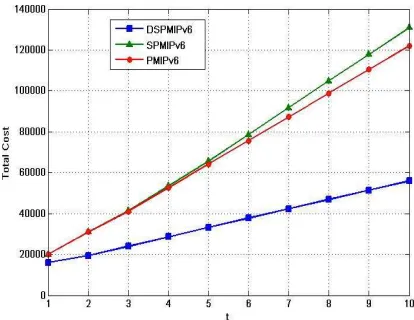
The effect of the delay of wired link on TC is shown in Figure 8. In order to calculate the TC, the delay of wired link between the communicating parties must be changed. However, the performance of DSMIPv6 is better than that of PMIPv6 and SPMIPv6 because of its shorter communication path as well as the relief of its LMA from being involved in the inter-handoff. When there is an increase in wired link delay, an increase occurs in the TC of all protocols. Due to the signaling reduction scheme in
which the authentication functions are performed in the LMA, the TC of the SPMIPv6 is less than that of the PMIPv6.
The effect of wireless link delay on the TC is shown in Figure 9. An increase in the TC of all protocols occurs when the wireless link increases. Among all the schemes DSPMIPv6 is the one that has the best performance. Remarkably, the differences in the performance of all protocols are maintained due to the fact that wired links are used in performing network-based protocol signals.
Figure 9: Impact of wireless link unit transmission cost on the TC.
[image:10.612.96.303.415.575.2]4079
Figure 10: Impact of Unit cost of binding update at LMA
[image:11.612.93.441.70.646.2]Figure 11: Unit cost of lookup at SLMA or DMAG
7. CONCLUSION
The requirements of energy efficiency in terms of signaling and mobility costs reduction are met by the SPMIPv6 because MN does not involve in mobility signaling. Nevertheless, the majority of the problems possessed by the PMIPv6 are inherited by the SPMIPv6 as a result of its reliance on a central and single LMA. Thus, the DSPMIPv6 is proposed in this study to improve the architecture of the SPMIPv6 by separating the control plane for location query from the data plane and using the DMAG to replace the MAG role. When a MAG is provided with links to the internet, which do mean paths moving across the LMA, it evolves into a DMAG. Therefore, the DMAG serves as a plain access router which sends packets to and from the internet. More so, functions that anchor mobility which is also able to forward without interrupting the flows of IP which an MN began while connected to it prior to moving to a new DMAG afterward are
possessed by a DMAG. Again, the SLMA of DSPMIPv6 has decreased to a plane only entity. It is proven by the analysis and numerical results that the performance of DSPMIPv6 is better than that of both PMIPv6 and SPMIPv6 in terms of local handoff latency, LMA load and cost of transmission. Future investigations could focus on the implementation of the DSPMIPv6 protocol to validate its scalability using a high and random mobility environment.
REFERENCES:
[1] I. F. Akyildiz, W. Su, Y. Sankarasubramaniam, and E. Cayirci, “A survey on sensor networks,” IEEE Commun. Mag., vol. 40, no. 8, pp. 102–105, Aug. 2002.
[2] Z. Zinonos and V. Vassiliou, “Inter-mobility support in controlled 6LoWPAN networks,” in 2010 IEEE Globecom Workshops, GC’10, 2010, pp. 1718–1723.
[3] N. Kushalnagar, G. Montenegro, D. E. Culler, and J. W. Hui, “Transmission of IPv6 Packets over IEEE 802.15.4 Networks,” 2007.
[4] C. Perkins, D. Jhonson, and J. Arkko, “2 Mobility Support in IPv6,” Rfc6275, vol. 25, no. 2, pp. 382–388, Jun. 2011.
[5] V. Devarapalli, R. Wakikawa, A. Petrescu, and P. Thubert, “Network Mobility basic support protocol,” Nemo-Basic-Support-02 (Work in, no. January 2005.
[6] M. C. Chuang and J. F. Lee, “FH-PMIPv6: A fast handoff scheme in Proxy Mobile IPv6 networks,” in 2011 International Conference on Consumer Electronics, Communications and Networks, CECNet 2011 - Proceedings, 2011, pp. 1297–1300. [7] K. Leung, “RFC 5213: Proxy Mobile IPv6,”
RFC, pp. 1–92, Aug. 2008.
[8] A. Muhanna and J. Korhonen, “Policy Profile and AAA Interfaces Requirements for PMIPv6.”
[9] M. M. Islam and E.-N. Huh, “Sensor Proxy Mobile IPv6 (SPMIPv6)—A Novel Scheme for Mobility Supported IP-WSNs,” Sensors, vol. 11, no. 12, pp. 1865–1887, Feb. 2011. [10] M. M. Islam, S.-H. Na, S.-J. Lee, and E.-N.
Huh, “A Novel Scheme for PMIPv6 Based Wireless Sensor Network,” Springer, Berlin, Heidelberg, 2010, pp. 429–438.
4080 2010, pp. 282–291.
[12] S. H. Hwang, J. H. Kim, C. S. Hong, and J. Sung, “Localized Management for Proxy Mobile IPv6,” Development, pp. 4–8, 2009. [13] M. S. Kim and S. Lee, “A novel load
balancing scheme for PMIPv6-based wireless networks,” AEU - Int. J. Electron. Commun., vol. 64, no. 6, pp. 579–583, 2010. [14] C. Perkins, D. Jhonson, and J. Arkko, “Mobility Support in IPv6,” Rfc6275, vol. 25, no. 2, pp. 382–388, Jul. 2011.
[15] H. A. Chan, H. Yokota, J. Xie, P. Seite, and D. Liu, “Distributed and Dynamic Mobility Management in Mobile Internet: Current Approaches and Issues,” J. Commun., vol. 6, no. 1, Feb. 2011.
[16] J. C. Zuniga, C. J. Bernardos, A. de la Oliva, T. Melia, R. Costa, and A. Reznik, “Distributed mobility management: A standards landscape,” IEEE Commun. Mag., vol. 51, no. 3, pp. 80–87, Mar. 2013. [17] J. Lee, J. Bonnin, P. Seite, and H. Chan,
“Distributed IP mobility management from the perspective of the IETF: motivations, requirements, approaches, comparison, and challenges,” IEEE Wirel. Commun., vol. 20, no. 5, pp. 159–168, Oct. 2013.
[18] J. Lee and Y.-H. Kim, “PMIPv6-based Distributed Mobility Management,” 2015. [19] S. Jeon, S. Figueiredo, and R. L. Aguiar,
“On the impacts of distributed and Dynamic Mobility Management strategy: A simulation study,” in 2013 IFIP Wireless Days (WD), 2013, pp. 1–6.
[20] S. Jeon, N. Kang, D. Corujo, and R. L. Aguiar, “Comprehensive performance evaluation of distributed and dynamic mobility routing strategy,” Comput. Networks, vol. 79, pp. 53–67, 2015. [21] H. Ali-Ahmad, M. Ouzzif, P. Bertin, and X.
Lagrange, “Distributed Mobility Management: Approaches and Analysis,”
2013 IEEE Int. Conf. Commun. Work., pp. 1297–1302, Jun. 2013.
[22] S. Gundavelli, K. Leung, V. Devarapalli, K. Chowdhury, and B. Patil, “Proxy Mobile IPv6,” IETF RFC 5213, no. August, pp. 1– 92, 2008.
[23] H. Ali-Ahmad, M. Ouzzif, P. Bertin, and X. Lagrange, “Performance Analysis on Network-Based Distributed Mobility Management,” Wirel. Pers. Commun., vol. 74, no. 4, pp. 1245–1263, Feb. 2014.
[24] Y. Fang, I. Chlamtac, and Yi-Bing Lin, “Channel occupancy times and handoff rate for mobile computing and PCS networks,”
IEEE Trans. Comput., vol. 47, no. 6, pp. 679–692, Jun. 1998.
[25] H. Jung, M. Gohar, J. I. Kim, and S. J. Koh, “Distributed mobility control in proxy mobile IPv6 networks,” IEICE Trans. Commun., vol. E94–B, no. 8, pp. 2216– 2224, 2011.