Dual Tree Complex Wavelet Transform (DTCWT) based
Adaptive Interpolation Technique for Enhancement of
Image Resolution
Mayuri D Patil
MTech Scholar CSE Department
TIT, Bhopal
Shivkumar S Tomar
Assistant Professor CSE Department
TIT, Bhopal
Setu K Chaturvedi,
Ph.D Head & ProfessorCSE Department TIT, Bhopal
ABSTRACT
Image resolution enhancement is one of the first steps in image processing. Enhancement of image with respect to spatial coordinates of the image, basically improves interpretability and perception of an image. Adaptive interpolation along with dual tree complex wavelet transform results in better quality superresoved images. Greater directional selectivity and phase information properties of redundant CWT implies superresolved image from original low resolution image. While improving the resolution of an image high frequency components are required to preserve other than enlarging the image. In this paper, dual tree complex wavelet transform (DTCWT) based superresolved imaging system along with non iterative orientation interpolation process is proposed. Image quality measuring factors such as PSNR value, RSNI approximation proves that efficiency of images obtained by proposed method is better than state of the art system of resolution enhancement.
General Terms
Image resolution enhancement, Interpolation.
Keywords
DTCWT, PSNR, RSNI
1.
INTRODUCTION
For many application of image processing, one cannot operate directly on the original input image as it is. For good quality of images, image enhancement is very first step in image processing. Image resolution enhancement is also widely useful for satellite image application which includes building construction, bridge recognition, in GPS technique [1]. In this paper we are concentrating on the image enhancement based on spatial elements of an image. Image resolution enhancement tasks are related to the pixel, means image processing task directly manipulate intensity of pixel in order to increase resolution of an image.
Image interpolation is widely used resolution enhancement method for various applications. Image interpolation is the process of using known data to estimate values at unknown locations [1]. Interpolating an image is generally common for making smaller imagery to fit a bigger screen in full screen mode. Mainly there are two types of interpolation algorithms. Adaptive Algorithm: These algorithms changes depending on what they are interpolating [2].
Non adaptive Algorithms: Adaptive Interpolation estimates lost pixel values using feature of surround pixel can get better image than non adaptive algorithm [2].
Linear interpolation includes nearest neighbor, bilinear, Bicubic interpolation. Traditional linear interpolation methods
do not work very well under the edge preserving criterion [1, 3]. Also they produce zigzag effects in interpolated image. Images obtained by these linear interpolation technique produces many artifacts like blurring, blocking [1]. Some non linear interpolation techniques have been proposed in recent year to preserve the sharpness of edges. Non linear interpolation methods are better at edge preserving than liner one.
The image processing task is best formulated by transforming images by applying specific task on image in transform domain. Then apply inverse transform to return image in the spatial domain. Various transforms can be applied on the images. But Wavelet transform has become useful computational tool for a variety of image processing task. Wavelet transform are also useful for removing unwanted noise and blurring artifacts from the image [4].
2.
LITERATURE SERVEY
Previously numerous of techniques are used for resolution enhancement of images in different applications. As discussed earlier, images such as satellite images consists of important details that plays vital role in many image processing applications and hence resolution enhancement is must for the same. Many of the researchers have proposed different methods to increase quality of images in accordance with resolution.
A. Temizel and T. Vlachos [5] Initial approximation to HR image is generating using wavelet domain zero padding. In this method wavelet transform is applied with filters. High resolution image is generated using zero padding of high frequency sub bands followed by inverse wavelet transform. Low resolution images are followed by wavelet domain resolution enhancement with zero padding i.e. WZP undergoes through spatial shifting to generate output high resolution image.
Yinji Piao, ll-hong Shin [6] uses correlation of subband with different sampling phases in DWT. By analyzing correlation between lower level subband and higher level subband, interpolation filters are design. First filter are estimated by applying wavelet transform to low resolution image. Estimated filters are used to estimate bands in higher level. And finally inverse wavelet transform is performed to enhance the resolution of input image.
Volume 80 – No 14, October 2013 Hasan Demirel and Gholamreza Anbarjafari [8] DWT
technique is for interpolating the images. But the images obtain from DWT and IDWT technique is not sharper compare to previous technique and comparatively low PSNR.
Hasan Demirel and Gholamreza Anbarjafar [9] used DT-CWT to decompose original image into different subband images. Then high frequency subband images and original low frequency image are undergoes the interpolation. By applying IDT-CWT on interpolated images we got high resolution image. Quality and PSNR of the super resolved image is also improves in this method.
There are some problems with wavelet domain also, it introduces artifacts like aliasing, any wavelet coeffient processing upsets the delicate balance between forward and inverse transform leading to some artifacts in the images. [4] Also produces lack of directional selectivity greatly complicates modeling and processing of geometric image features like ridges and edges. One solution to all these problems is Complex Wavelet Transform (CWT). CWT is only approximately magnitude or phase, shift invariant and free from aliasing. [4]
In order to increase resolution of images with preserving geometric properties of images Covariance based interpolation algorithm is used along with DTCWT is proposed in this paper. This paper is organized as follows: section 3 describes brief description of adaptive covariance based interpolation algorithm. Section 4 illustrates the Dual Tree Complex Wavelet Transform. Last sections describe result analysis and experimental setup of proposed system with traditional methods.
3.
COVARIANCE BASED ADAPTIVE
INTERPOLATION
In resolution enhancement many of authors used traditional interpolation techniques for enlarging the image for various applications. As stated earlier linear interpolation methods increases the resolution of image but introduces blurring at edges like artifacts [1].This paper overcome all these artifacts by introducing covariance based Adaptive interpolation algorithm to generate superresolved image.
Intensity of pixel is less evolved along the edges while intensity of pixel is more evolved across the edge orientation [10]. Other orientation methods of interpolation estimates orientation across the edges of an image and using this orientation, interpolating coefficients are calculated.
Main aspect of multiresolution analysis of an image is to generate high resolution covariance from low resolution covariance. For this purpose adaptive covariance based interpolation algorithm use geometric duality concept. This duality principle sates that by calculating relation between low resolution covariance and high resolution covariance is used to couple the pair of pixel.
The algorithm is operates as follows:
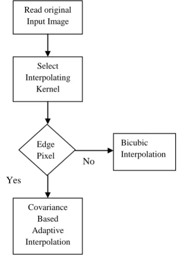
Step 1: Select Interpolating Kernel: Interpolating kernel is used for detecting the edge of images. For this purpose Sobel interpolating kernel is used for detecting the edge.
Step 2: Determine the pixel: If detected pixel is pixel of edge then covariance based adaptive interpolation is applied. Otherwise linear bicubic interpolation algorithm is applied for non edge pixel.
Local covariance at high resolution level can be used to find intensity of pixel.
Consider low resolution image X(i, j), High resolution image Y(i, j) & Magnification ratio is 2. C is matrix of size 4× m2. While m is local window of size m×m, column vector y is of size m2. Then low resolution covariance (r) and high resolution covariance (R) is computed as:
…….... (1)
………. (2)
Then using Wiener filtering, linear interpolation pixel intensity is as:
………. (3)
[image:2.595.342.525.295.562.2]contain interpolating wt. of 4 neighbors. These weights are multiply with corresponding neighbor and take addition of all to get new pixel. In this algorithm pixel intensity is calculate using diagonal neighbour. Following diagram represent the flow chart of Covariance based Adaptive Interpolation.
Fig 1: Flow Chart of Covariance Based Adaptive Interpolation
4.
DUAL TREE COMPLEX WAVELET
TRANSFORM (DTCWT)
Nick Kingsbury [11] proposed that dual tree complex wavelet transform is used to overcome disadvantages of traditional wavelet transform. The complex wavelet transform (CWT) is complex valued extension to standard DWT. CWT use complex value filtering that decomposes the real/complex signal into real and imaginary parts in transform domain. The real and imaginary coefficient is used to compute amplitude and phase information. DTCWT have separate sub bands for positive and negative orientations. DTCWT calculate complex transform of signal using two separate discrete wavelet transform (DWT) decomposition. DWT decomposition produces two parallel trees [11]. We use 1D DTCWT, consider (hx + jgx) where, hx is the set of filters {h0, h1}, and
Read original Input Image
Select Interpolating
Kernel
Edge Pixel ?
Covariance Based Adaptive Interpolation
Bicubic Interpolation No
gx is the set of filters {g0, g1} both sets in only x-direction
(1-D). The filters h0 and h1 are the real-valued lowpass and
highpass filters respectively for real tree. The same is true for g0 and g1 for imaginary tree. DTCWT has good directional
selectivity as compare to other methods. Also it has reduced shift variant property [11].
Following are features of DTCWT:
Approximate shift variant.
Good directional selectivity.
Perfect reconstruction using short linear filters.
Limited redundancy.
Efficient order n computations.
5.
PROPOSED SYSTEM
The main damage of interpolated image is high frequency component i.e. edges which is due to blurring effect of interpolation. So quality of satellite image can be enhancing by preserving high frequency component of images i.e. edges. The propose system first decomposes original low resolution input image into six complex valued high frequency sub band images and low frequency sub band images [12]. High frequency sub band images are interpolated. In complex wavelet domain low frequency images are obtaining from low lass filtering since it contains low frequency components. Therefore rather than using low frequency sub band images contain less information than original input image. Therefore using input image is interpolated using covariance based interpolation algorithm. Using new interpolating algorithm high frequency components are preserve in output interpolated image.
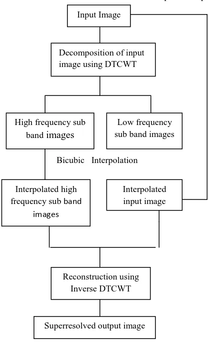
DTCWT has been applied for preserving high frequency components of images. As it has good directional selectivity and shift invariant property. As shown in fig. 2 original input image is decomposes using DTCWT, as it produces six complex valued high frequency sub band images and low frequency subband images. Six complex valued high frequency subband images undergo bicubic interpolation. The resultant interpolated high frequency subband images and interpolated input image using covariance based interpolation are goes through inverse DTCWT to get superresolved image of original input image.
[image:3.595.319.528.74.418.2]In summary, Propose method of super resolution not just interpolated the image but also preserve the high frequency component of images. So that resultant output image is super resolution of the original input image. The output images obtain by two different interpolation techniques. So that complexity of this proposed system is more than other technique. One disadvantage of using proposed method is computational time require is more as it required approximately 1300 multiplication for calculating the interpolating coefficient [7]. Following figure shows architecture of proposed system.
Fig 2: Architectural Diagram of Propose System Fig 3 shows the resultant images obtain by the proposed system. Figure (a) shows original input image and figure (b) shows output image obtain by applying DTCWT and Bicubic Interpolation figure (c) shows the resultant image by proposed System. From these figures we can shows the efficiency of proposed method.
(a)
(b)
Bicubic Interpolation Input Image
Decomposition of input image using DTCWT
High frequency sub
band images
Low frequency sub band images
Interpolated high frequency sub band
images
Interpolated input image
Reconstruction using Inverse DTCWT
Superresolved output image
Volume 80 – No 14, October 2013
(c)
Fig 3: (a) Original Low /resolution Input Image (b) Superresolved Image Using Bicubic and DTCWT (c)
Superresolved Image Using Proposed System
6.
EXPERIMENTAL SETUP
For implementation of the resolution enhancement system Matlab is used. The images provided by Google Earth and Satellite Imaging Corporation of different resolution are used for testing purpose.
7.
RESULT ANALYSIS
The proposed system has been tested on different images. In order to shows the superiority of the proposed system over existing system. In order to prove that images resulting from the propose system are having better quality than any other methods. For quantitative measures we consider here different quality measures of the image such as Peak Signal to Noise Ratio (PSNR), Root Mean Square Error (RMSE) and Ratio of Squared Norm of Approximation Image (RSNI) are calculated.
PSNR of the image is computed using following formula [11, 12]
………. (4)
Here R is the maximum fluctuation in the input image (255 here as image are represented using 8-bit) and MSE is representing Mean Square Error between the given input image I1 and output image I2 which can be computed by
following[11, 12]
………. (5)
R and C are rows and columns of an image. Table 1 shows PSNR values of different images.
Table 1: PSNR Result Comparison of Proposed System and State of the Art Resolution Enhancement
Methods.
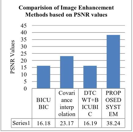
[image:4.595.94.242.72.222.2]Higher PSNR value indicates good quality of image. Following figure shows the graphical representation of PSNR values of tested images.
Fig 4: Graphical Representation of PSNR Results
Squared Norm of the Image (RSNI) approximation to the input image is used to show the improvement in approximate image. RSNI is calculated as follows
……… (6)
Table 2 shows the RSNI result comparison of proposed system and state of the art resolution enhancement methods.
Table 2: RSNI Result Comparison of Proposed System and State of the Art Resolution Enhancement Methods.
Following figure shows the graphical representation of RSNI values of images. If RSNI is approximate to 1 then quality of image is good.
BICU BIC
Covari ance interp olation
DTC WT+B ICUBI C
PROP OSED SYST
EM
Series1 16.18 23.17 16.19 38.24
0 5 10 15 20 25 30 35 40 45
P
SNR
Valu
es
Comparision of Image Enhancement Methods based on PSNR values
Sr. No.
Bicubic Interpolati on
Covariance based interpolation
DTCWT+ Bicubic
Proposed Method
1 0.6692 0.9256 0.6694 0.996
2 0.4256 0.7416 0.425 1.0026
3 0.6935 0.905 0.692 1.025
Sr. No .
Bicubic Interpola tion
Covariance based interpolation
DTCWT+ Bicubic
Proposed Method
1 16.18 23.17 16.19 38.24
2 10.12 20.4 10.12 37.54
[image:4.595.315.533.111.326.2]Fig 5: Graphical Representation of RSNI Results Root Mean Square Error (RMSE) is square root of MSE hence it is calculated as follows [11, 12]
……… (7)
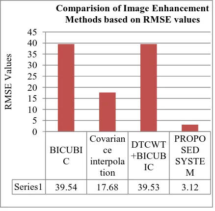
[image:5.595.316.535.72.287.2]Table 3 shows the RMSE result comparison of proposed system and state of the art resolution enhancement methods.
Table 3: RMSE Result Comparison of Proposed System and State of the Art Resolution Enhancement Methods
Lower the RMSE value means greater the quality of image. Following figure shows graphical representation of RMSE values of different images
Fig 6: Graphical Representation of RMSE Results
8.
CONCLUSION AND FUTURE WORK
As a part of this paper, we have seen how resolution can be enhance using covariance based edge directed interpolation along with DTCWT. Later on different image components are merging together to form a high resolution image. Although the propose method outperforms the existing techniques of super resolution, but scope of improvement still exits. As this method involves multistage process, the number of computations is more therefore simulation time is increase. So as future work, modifications may be introduced to reduce the computation time.
9.
REFERENCES
[1] Raman Maini and Himanshu Aggarwal,”A Comprehensive Review of Image Enhancement Techniques” Journal of computing, volume 2, issue 3, march 2010.
[2] Zhang Min, Wang Jiechao, LI Zhiwei and LI Yonghua ,“An Adaptive Image Zooming Method with Edge Enhancementʹ” ,3rd International Conference on Advanced Computer Theory and Engineering (ICACTE), 2010.
[3] Zhou Dengwen and Shen Xiaoliu , “ An Effective Color Image Interpolation Algorithm”,4th International Congress on Image and Signal Processing,2011.
[4] Felix C. A. Fernandes, Rutger L. C.,”A New Framework for Complex Wavelet Transform” IEEE Trans. On signal processings, vol.51,no.7,July,2003.
[5] A.Temizel and T. Vlachos, “Wavelet Domain Image Resolution Enhancement using Cycle-spinning”, Electronics Letters, Vol.41, No.3, Feb. 2005
[6] Y. Piao, I. Shin, and H. W. Park, “Image resolution enhancement using inter-subband correlation in wavelet domain”, in Proc. ICIP, vol 1,2007.
[7] Hasan Demirel and Gholamreza Anbarjafari,”Image Resolution Enhancement by Using Discrete and Stationary Wavelet Decomposition” IEEE transactions on image processing, vol. 20, no. 5, may 2011.
[8] Hasan Demirel and Gholamreza Anbarjafari,”Discrete Wavelet Transform-Based Satellite Image Resolution
BiCubi c
Covari ance interp olatio n
DTCW T+Bicu bic
Propo sed Metho
d
Series1 0.6692 0.9256 0.6694 0.996
0 0.2 0.4 0.6 0.8 1 1.2
R
SNI
v
alu
es
Comparision of Image Enhancement Methods based on RSNI values
BICUBI C
Covarian ce interpola
tion
DTCWT +BICUB
IC
PROPO SED SYSTE
M
Series1 39.54 17.68 39.53 3.12
0 5 10 15 20 25 30 35 40 45
R
MSE
Valu
es
Comparision of Image Enhancement Methods based on RMSE values
Sr. No.
Bicubic Interpolatio n
Covariance based interpolation
DTCW T+Bicu bic
Proposed Method
1 39.54 17.68 39.53 3.12
2 79.48 24.33 79.485 3.38
[image:5.595.49.292.433.548.2]Volume 80 – No 14, October 2013 Enhancement”, IEEE Trans. geoscience and remote
sensing letters,vol.49,no.6, June 2011..
[9] Hasan Demirel and Gholamreza Anbarjafari,”Satellite Image Resolution Enhancement Using Complex Wavelet Transform” ,IEEE Trans. geoscience and remote sensing letters,vol.7,no.1,January 2010.
[10] Nick Kingsbury,”Shift invariant properties of the dual tree Complex Wavelet Transform” IEEE Trans. On signal processing letters, 1999.
[11] R. C. Gonzalez, R. E. Woods, ʹDigital Image Processingʹ, 2nd ed., Prentice Hall.
[12] A K Jain, ‘Fundamentals of Digital Image Processing’, Prentice Hall, NJ, 1990.
[13] W. K. Pratt, Digital image processing, Prentice Hall, 1989.
[14] R. C. Gonzalez, R. E. Woods, “Digital Image Processing using Matlab”, 2nd ed., Prentice Hall.