Dynamic Source Quick Route Rebuilding Algorithm
for Random-access OFDMA Adhoc Network
Sunil Jacob
Associate Professor, Dept. of ECE SCMS School of Engineering and Technology
Angamali, Kerala, India
Dr. R. Dhanasekaran
Professor & Director- Research Syed Amal Engineering College Ramanathapuram, Tamil Nadu, IndiaABSTRACT
This paper focusses on maintaining message continuity in a mobile Adhoc network. The dynamic source quick route rebuilding algorithm (DSQRRA) provides continuity in packet routing to reach the next possible neighboring node in order to avoid resending the packet from the source. DSQRRA calls for
mobility management and scalable design. Mobility
management is done through information exchanges between moving hosts in the Adhoc wireless network. The DSQRRA uses cooperative protocols to coordinate with the Adhoc on demand Distance Vector routine (AODV) protocol for shortest route rebuilding in Random Access OFDMA network. The algorithm gives next alternative route immediately once there is a break in the link. Simulations have been performed to analyze the performance of AODV with and without DSQRRA. The AODV with DSQRRA reduced memory occupation and route broadcasting. It has minimized packet looping. Simulations also show that DSQRRA provides quick delivery of packet from source to destination.
Keywords
Cooperation ratio, OFDMA, RDF, SNR
1.
INTRODUCTION
Random access wireless relaying networks allow relay nodes to participate in the transmission of information when they are neither the initial source nor the final destination. Orthogonal amplify and forwarding for multi-hop communications has been the focus of much of recent research [1-3]. Consider the case of orthogonal relay transmission. While orthogonal relay schemes are attractive for wide band communications, it has been shown that for amplify and forward relays, shared bandwidth transmissions schemes can provide higher capacity [4]. OFDMA is becoming the chosen modulation technique for wireless communication. OFDMA can provide large data rates with sufficient robustness to radio channel impairments [5]. In an OFDM scheme a large number of orthogonal, overlapping narrow band sub-carriers are transmitted in parallel. The carrier divides the available transmission bandwidth. The attraction of OFDM is mainly because of its way of handling the multipath interference at the receiving node. The frequency selective fading and inters-symbol interference which are generated due to multipath phenomenon is compensated using OFDM principle. Recently, relay assisted multi-hop communications has become a prominent candidate to combat the impairments of the wireless channel by exploiting spatial diversity without needing to deploy physical antenna arrays. [6-8]. Relay assistance also mitigates the effects of path loss and provides the source nodes with extended battery life. [9-11] . Results on the capacity of the full duplex relay channel go back to (12). Relay transmission schemes are derived in [13] using half
duplex transmission. Recently reference [14] showed that the uplink capacity of two user system can be increased by using cooperation, where each user also acts as a relay for the other. Recently researchers have recognized that spatial diversity can be achieved in multi user communication systems even if the nodes in the system each have only one antenna. The concept of user cooperation diversity where nearby users in a cellular system form cooperative “partnerships” by sharing their antennae to achieve increased rate or decreased outage probability in the uplink. Relay assisted transmission is expected to improve the performance of multi user system as well [15] [16]; such networks henceforth referred to as multiuser relay networks are one where each relay node would serve multiple users, and the total transmission power budget for each relay node will be limited. Cooperative transmission is unique however, in that it requires autonomous nodes to allocate transmit power between non-cooperative and cooperative transmission [17]. Inefficient allocation of transmit power could lead to worse power efficiency than no cooperation. Individual user’s transmission should be relayed with a fraction of the power from its corresponding relay node. In such a case the total relay power should be allocated between the transmissions of information from the sources that relay over this node in order to obtain the best performance. The critical power for asymptotic connectivity in wireless networks, the stochastic analysis, control optimization and applications can be applied to cellular, WLAN, ad-hoc and hybrid networks in order to increase coverage, throughput and capacity [18]. The optimum power allocation for relay networks is studied up to date in [1]-[5] for several relay transmission schemes with a single source-destination pair. In contrast, in this paper we will consider power allocation for a relay assisted OFDMA network with multiple source-destination pairs. The primary focus of this paper is on the problem of how to allocate transmit power between multiple random source-destination pairs, in order to maximize power efficiency in a wireless communication system with different cooperating nodes communicating independent information over orthogonal frequency sub channel to multiple random destinations. The algorithm developed gives next alternative shirtest route immediately once there is a break in the link. Simulations have been performed to analyze the performance of AODV with and without DSQRRA.
2.
SYSTEM MODEL AND
ORTHOGONAL TRANSMISSION AT
THE SOURCE
assumed to be known to both sources and destination nodes . In this section, we consider an orthogonal transmission from sources to the relay using frequency division. When S1 and S2 transmit to the R in orthogonal frequency slot instead of simultaneous fashion the destinations will not receive any direct interference from the sources.We consider a relay network with a single relay and two source-destination pairs (Si, Di) where i=1, 2. Each source only wishes to communicate with its dedicated destination such that the relay helps the source or the source transmits directly without help of the relay depending on whichever is more power efficient.
β1
α1 γ1
β2
h12 h21
α2 γ2 β4
β3
Figure 1: System model
We consider the signal received from S1 and S2 or both. Regenerate the signal and decode and forward it to their corresponding destinations. The signal received by the destination in the ith user’s first channel is
y
di 1= P
siβ
ix
si+ n
di 1(1)
Where xsi is the symbol transmitted by user i, Psi is the transmit power of user i and βi denotes the normalized channel gain from user i to the destination with ndi1 as the zero mean additive white Gaussian noise (AWGN) with unit variance. Similarly the received signal at the relay node k to which user i is assigned is
y
ri= P
siα
ix
si+ n
ri(2)
Where αi is the normalized channel gain from user i to the assigned relay node k and nri is the zero mean AWGN with unit variance. In the second channel of the ith user, the kth relay node transmits xri, and the corresponding received signal at the destination is
y
di 2= P
riγ
ix
ri+ n
di 2(3)
Where xri, Pri and γi denote the signal transmitted for user i from the kth relay node, the transmit power of the kth relay node dedicated to user i and the normalized channel gain from the kth relay node to the destination of the ith user with a zero mean and unit variance AWGN ndi2, respectively. We assume that each relay node has a total power constraint.
Pri i∈Ak
≤ PRk ,total
Where Ak denotes the set of source nodes that relay their information through node k. It is also assumed that the relay nodes have the channel state information of the source to destination, source to relay and relay to destination links of all source nodes they serve. We consider the regenerative decode and forward transmission scheme in which the transmission from the source node is received reliably at the relay node, the relay node decodes the signal, re-encodes it with the same code book used in the original source nodes transmission and
transmits the signal in the second channel of the source node. The optimum power allocation problem at the relay nodes is posed as
Such that
max
{Pri}i=1,….KC
sum=
KC
i,RDFi=1
(4)
Pri i∈Ak
≤ PRk ,total
Pri ≥ 0 ∀i, k
Where Ci,RDF is the capacity of saingle source node with regenerative decode and forward.
In RDF the relay node used must decode the signal in an efficient way. Thus, the individual capacity of a relay assisted source node cannot exceed the capacity of the source node to relay link. This constraint leads to several important observations in terms of optimum power allocation. When the direct link, is better than the relay link for source node i, the minimum of the capacity upper bounds of the direct link and source node to relay link is the better. In this case, the capacity of the direct transmission is higher than that of the relay assisted transmission. Since by employing direct transmission for source node i, the individual capacity of source node i is maximized, and the relay has the potential to improve the sum capacity by investing its power in assisting the remaining source nodes, the relay power allocated to source node i should be
P
ri= 0 if α
i2≤ β
i2, ∀i = 1, … … K (5)
The maximum individual capacity of source node i is upper bounded byC
upper DF=
2K1log(1+P
siα
i2), ∀I (6)
due to the decodability constraint at the relay. Thus, allocating more power of the relay node for the transmission of the source node beyond a threshold will not increase the individual capacity of the source node. These constraints should be taken into account for the power allocation problem in RDF relay nodes.
In the case of RDF relay transmission, the individual capacity of source node i is
Ci,RDF = min(2K1 log 1 + Psiβ2i + Priγi2 , Cupper DF)
(7)
The following classification of source nodes for RDF networks Minimum power source nodes (MnPN): The group of
source nodes that are assigned minimum power at their existing relay node and still do not achieve the individual capacity upper bound indicated by (4). In other words, these are the nodes whose strength would be increased further if more total power were available with the relay node.
Maximum power source nodes (MxPN): The group of source nodes that achieve the maximum individual capacities indicated by (4), with the help of the relay node. Source nodes with low quality direct links and high quality relay to destination links, for these source nodes, even if more total relay power were available, the capacities of individual would does not show any improvement. Non assisted source nodes (NAN): The group of source
nodes that are not assisted by the relay node. The source node in this set have either high quality direct links or low quality relay to destination links.
The AWGN at the relay and destinations are independent with variance N0. Channels have independent Rayleigh fading, that is the channel power gains αi=1 or 2, γi=1 or 2, βi=1 or 3 and βi=2 or 4, i=1,2 are exponential with means (mαi=1 or 2, mγi=1 or 2, mβi=1 or 3,
S
1R
D
1mβi=2 or 4) respectively where the means include the distances and shadowing effect. Here αi represents the channel from Si to R, γi from R to Di and βi from Si to Di for i=1or2. Also β4 (β2) represents the interference link from S1 (S2) to D2 (D1). We will denote the network state, which includes the instantaneous power gain of each channel (α1,α2,γ1,γ2,β1,β2,β3,β4) by θ. The transmission power of S1, S2, R and total network power are denoted by PS1, PS2, PR and Ptotal respectively.
In this work, we consider the total achievable end to end rate RTu= R1+R2, where Ri denotes the transmission rate from Si to Di for i=1,2. Our goal is to minimize the outage on the total rate that is the probability that the total rate RTu cannot be supported subject to long term total network power constraint, Ptotal: We first consider the minimum total power Ptotal, min (θ) needed to guarantee total rate RTu for each channel state (θ). We then apply a threshold Pth, Ptotal,min (θ) such that the sources transmit only if Ptotal,min (θ) is less than this threshold power level Pth. For the channel states where Ptotal,min (θ) exceeds the threshold, the sources are not allowed to transmit and the system will be in outage. Consider the cases:
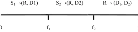
Case 1
In this case both sources utilize the relay for transmission to their corresponding destinations and are high potential source node.
S1→(R, D1) S2→(R, D2) R→ (D1, D2)
[image:3.595.55.279.341.394.2]0 f1 f2 1
Figure 2: Both sources utilize the relay for transmission
In Figure 2,S1 transmits to R for 0≤f≤f1, S2 transmits to R for f1<f≤f2 and R transmits the aggregate information for f2<f≤1 to the destinations using same Gaussian codebook with respect to the sources. Since the sources transmit in orthogonal frequency slot, their corresponding destinations receive non interfered signals and broadcast region of the R→ (D1, D2) is shifted accordingly. Using these observations and considering the Regenerative decode and forwarding strategy of the relay, the transmission rates can be written as
R
(S1→R)1≤ f
1log(1 + ∝
1P
S1)
N
0R
(S22→R)≤ (f
1
− f
2)log(1 + ∝
2P
S2)
N
0R
(S1,R→D1)1≤ f
1log(1 + β
1P
S1) + (1
N
0− f
2)log(1 + γ
1P
R1N
0)
R
S22 ,R→D2≤ (f
2
− f
1)log(1 + β
3P
S2) +
N
0(1 − f
2)log(1 + γ
2P
R2(γ
2P
R1+N
0))
(8)
Where f1 is the frequency allocated for the transmission of S1→R, (f2-f1) is the frequency allocated for the transmission of S2→R, PR1 and PR2 are the relay powers dedicated for the transmission of S1, S2 respectively.Minimum total power satisfying total end to end rate RTu requires optimizing f1, f2, PS1, PS2, PR1, PR2 and can be written as
P
total(C1)= min
f1,f2,PS1,PS2,PR 1,PR 2
(f
1P
S1+ f
2− f
1P
S2+
1 − f
2P
R1+ 1 − f
2P
R2) (9)
Such that R1+R2≥ R Tu (R1, R2) satisfy Eq (1) with
R
1= min(R
1 S1→R, R
1S1,R→D1
) and
R2= min(R2 S2→R , R S22,R→D2 )
Case 2
In this case only one source, say S1 uses R and the other source S2 directly transmits its signal to D2, the source nodes in this case are the Minimum power source node with low quality direct links and high quality relay to destination links.The frequency allocation of this scheme can be seen in Figure 3. S1(S2)→(R,D1(D2) S2(S1)→D2(D1) R→D1(D2) 0 f1 f2 1
Figure 3: One source uses relay and the other source transmits directly
Due to orthogonal transmission S2 does not cause interference at R, and D2 does not observe interference from R during (f2<f≤1). The end to end transmission rates can be written as follows:
R
2(S2→D2)≤ (f
2− f
1)log(1 + β
3P
S2)
N
0R
1(S1→R)≤ f
1
log(1 + ∝
1P
S1)
N
0R
(S11 ,R→D1)≤ f
1log(1 + β
1P
S1) +
N
0(1 − f
2)log(1 + γ
1P
R1N
0)
(10)
Minimum total power in this case will be
P
total(C2)= min
f1,f2,PS1,PS2,PR(f
1P
S1+ f
2− f
1P
S2+
1 − f
2P
R) (11)
Such that R1+R2≥ RTu where
R1= min(R1 S1→R , R1 S1,R→D1 )
R2= R S22 →D2
satisfy Eq (10)
Case 3
In this case neither S1 nor S2 utilize R and transmit in optimized orthogonal frequency slot in Figure 4. In this case the sources are non relayed source node.
S1→ D1 S2→D2
0 f 1 1 Figure 4: Sources directly transmit the information to
destination without relay nodes
Then
R1≤ f1log(1 + β1PS1 N0)
R
2≤ (1 − f
1)log(1 + β
3P
S2N
0)
(12)
Minimum total power will satisfy the following such that
P
total(C3)= min
f1,Ps1,PS2,
(f
1P
S1+ 1 − f
1P
S2) (13)
Such that R1+R2≥RTu
Where (R1, R2) satisfy equation (12).
Ptotalorth = min(Ptotal (C1)
, Ptotal(C2), Ptotal(C3))
Similarly we can formulate Case 2 and Case 3 where only one source or both transmit directly for constant frequency allocation strategy and derive dynamic power allocations.
3.
COOPERATIVE PROTOCOL
The data transmission of each user occurs in two pre-assigned channels that are having different frequencies. The user broadcasts its signal in the first channel and the relay node retransmits this user’s information in the second channel. We denote the ith source’s zero-mean unit-variance information symbol as xi, the ith source’s amplitude in the kth frequency slot as ai[k]≥0 and the j
th
source’s transmission in the kth frequency slot as fi[k]. The jth source in the system receives the signal sent by the ith source in frequency slot k as
rij[k]=hijfi[k]+vij[k]
Where hij is the (scalar) channel gain in orthogonal channel i between source i and source j and vij[k] is the zero mean noise in this channel with variance σv2>0.
The two source regenerative decode and forward cooperative transmission protocol is given by Eq (14) and Eq (15).
Two source Regenerative decode and forward cooperative protocol
Frequency slot 1 Frequency slot 2
Source 1 f1[1]=a1[1]x1 f1[2]=a1[2]r21[1] (14) Source2 f2[1]=a2[1]x2 f2[2]=a2[2]r12[1] (15)
The signal received by the destination in the ith orthogonal channel in frequency slot k is given as
yi[k]=βifi[k]+Wi[k]
Where βi is the scalar channel gain between the i th
user and the destination and Wi[k] is the zero-mean noise in this channel with variance σW2>0. The destination forms the decision statistic for the ith user’s information symbol as a linear combination of the two relevant observations.
ie y1=b1[1]y1[1]+b2[2]y2[2] y2=b2[1]y2[1]+b1[2]y1[2]
where b1[k] and b2[k] are the linear combination parameters selected by the destination to maximize the SNR of the decision statistics. Note that there is no multi-access interference (ie frequency selective fading and ISI) due to the orthogonality of all transmissions in this transmission.
4.
TRANSMIT POWER AND SNR
ANALYSIS
Allocating transmit power in order to achieve a pair of fixed SNR targets, denoted as SNR1 and SNR2 at the destination. In the absence of cooperation, the orthogonality of the sources makes the solution to this problem straightforward.
The SNR target will be satisfied if Pi= ai2 1 ≥ (σw2 βi2)SNRi
Where Pi denotes the transmit power of the ith source.
4.1
Transmit power and cooperation ratios
Denoting the transmit power source i in frequency slot k as Pi[k], the transmit power in each frequency slot are taken as Source 1 →Frequency slot 1 →
P1 1 = a12[1]
Frequency slot 2 →
P
12 = a
122 (h
212a
221 + σ
v2(16)
Source 2 →
Frequency slot 1 →
P2 1 = a22[1]
Frequency slot 2 →
P2 2 = a22 2 (h122 a12 1 + σv2) (17)
The total transmit power for source i is given as
Pi=Pi[1]+Pi[2] and the total transmit power over all sources is given as Ptotal=P1+P2
From the power expressions of Eq (16) and Eq (17), we can define a “cooperation ratio” parameter for each source in the system. The ith source’s cooperation ratio is defined as the ratio of the power of the ith source’s cooperative retransmission to the power of the original transmission of source j (i≠j). Using the results from Eq (16) and Eq (17) we can write the cooperation ratios for the ith source as
αi=
Pi 2 Pj 1 =
ai2 2 (hij2a j 2 1 +σ
v
2)
aj2[1] (18)
i,j Є {1,2} For 0≤αi<∞ and j≠i.
We note that the non cooperative case corresponds to α1=α2=0 We are now ready to state our results for RDF relay networks using cooperative protocols. The optimal power allocation for RDF relay networks results in three source node sets, namely minimum power source nodes, maximum power source nodes and non assisted source nodes for each relay node.
1. The optimum relay power dedicated to max power source node i, and the achieved individual capacity of source node i, are
Pri = μ 1
k,RDF −
1+Psiβi2 γi2 ∗;
C
i,RDF=
2K1log(γ
i2μ
k,RDF)
(19)
Respectively, where (.)* = max(.,0) and µk,RDF is the water level for the kth RDF relay node that satisfies i∈AkPri =
PRk ,total .
2. The optimum relay power dedicated to minimum power source node i, and the achieved individual capacity of source node i, are
P
ri=
Psi(αi2−β
i
2)
γi2
;
C
i,RDF=
12K
log(1 + P
siα
i 2)
(20)
The non assisted source nodes set involves the source nodes that either have better direct links than the source to relay links, ie αi2≤ βi2, or high quality direct links or low quality relay to destination links, ie., 1+Psiβi2
γi2 ≥ 1
μk ,RDF
The optimum power allocation for RDF networks is a modified water-filling solution (1). where each source node has both a base and an upper water level. The base level,
1+Psiβi2
γi2 is due to the direct link and the channel gain of the
relay node to the destination for each source node, whereas the upper level, Psi αi
2−β
i 2
γi2 +
1+Psiβi2
γi2 , is due to the
the quality of the direct links of the source nodes, and its own channel gain to the intended destinations, and will try to help the source nodes with low quality direct links and high quality relay to destination links.
It is important to note that the optimum power allocation for the uplink of relay assisted FDMA network tries to equalize the individual capacities achieved by each source node thus also increasing the symmetric capacity of the system. The source nodes that are not equalized in terms of individual capacities are the source nodes that either have a low quality source node to relay link (the set of minimum power source nodes, and a subset of non assisted source nodes) or a very high quality direct link, (non assisted source nodes).
5.
SIMULATION RESULTS
[image:5.595.309.545.75.249.2]In this case from section I the orthogonal transmission has better outage performance than constant frequency allocation schemes and direct transmission without relay. The performance difference between them at the sources occurs due to the fact that in orthogonal transmission each source is constrained to transmit in non-overlapping frequency slots. The gains are present despite interference caused by simultaneous transmission. In the same figure for orthogonal transmission at the source provides outage probability performance as minimum compared to constant frequency allocation scheme. Figure 5 shows that by using DSQRRA algoritm route3 is the shortest path from the source to the destination for a given set of nodes. the performance also shows that if there is any discontinuity in the path the other shortest path will be established between the source and the destination. In route 1 we have used AODV and the route covers longer distance. In route 3 we have used AODV with DSQRRA and get the shortest path from source to destination. If there is any break in the node path for route 3 the message continuity is maintained by route 2.
Figure 5: Comparison of distance covered for various routes using DSQRRA with and without AODV
In Figure 6 for RDF, the optimal power allocation tries to help the weak source nodes that it can efficiently assist, providing fairness among the source nodes. We note that, for low potential source nodes with low quality direct links and high quality relay to destination links the benefit provided by the relay node increase with increased relay power compared to non relayed and high potential source node. Thus, an appropriate relay selection strategy for RDF relay networks should be to select the relay nodes that will provide both high quality source to relay and relay to destination links.
Figure 6: Comparison of power allocated for various source nodes in different routes
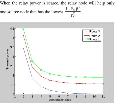
When the relay power is scarce, the relay node will help only one source node that has the lowest 1+Psiβi
2
[image:5.595.310.542.286.493.2]γi2 .
Figure 7: Comparison of reduction in transmit power as cooperation ratio increases for different routes
Figure 7 uses the analysis of section II to examine the transmit power required by each source, at a fixed level of cooperation specified by α1 and α2. We consider the scenario of time-invariant channels.
In this section, we examine the transmit power requirement for the case when all of the channels in Figure 1 are modelled as time invariant. We first consider the case where β1=β2 and h12=h21 ie symmetric channel.. A simultaneous reduction in individual transmit power P1 and P2 with respect to the non-cooperative case is possible. Moreover, the total required transmit power is maximized when α1=α2=0. In other words, cooperation can provide a reduction in total transmit power with respect to the non-cooperative case. The result can be explained by the fact that if all of the channels are symmetric, it is more effective to put power into the first frequency slot than to regenerate decode and forward the noisy signal from the other source in the second frequency slot. Figure 7 shows the required transmit powers for different routes as a function of the cooperative ratios α1 and α2 for a particular example of the symmetric time invariant channel case. The route 3 with DSQRRA has the requirement of minimum transmit power.
0 2 4 6 8 10 12 14 16 18 20
0 0.1 0.2 0.3 0.4 0.5 0.6 0.7
Route Node position
D
is
ta
n
c
e
c
o
v
e
re
d
(
m
e
te
r)
Route 1 Route 2 Route 3
1 2 3 4 5 6 7 8 9 10 11
1 1.5 2 2.5 3 3.5 4 4.5
cooperation ratio
T
ra
n
s
m
it p
o
wer
p
o
wer
Route 3 Route 2 Route 1
1 2 3 4 5 6 7 8 9 10 11
0 0.2 0.4 0.6 0.8 1 1.2 1.4 1.6 1.8
Relay power
Op
tim
u
m
p
o
wer
a
llo
c
a
tio
n
a
llo
ca
tio
n
[image:5.595.55.288.464.619.2]In this case it can be shown that like the symmetric case, cooperative transmission can reduce the individual transmit power for one source at the expense of increased transmit power for the other source and as the cooperation between different node increases the requirement for transmit power decreases in all the three different routes. A simultaneous reduction in individual transmit power is not possible unlike the symmetrical case, however as long as the source-source channel is better than the weaker source-destination channel, cooperation can reduce the total required transmit power with respect to the non cooperative case when the source with the stronger source-destination channel cooperates.
6.
CONCLUSION
OFDMA based scheme removes the interference among the source. Simulation shows that for symmetric network, i.e. when both sources have comparable overall average channel gain, by using DSQRRA algorithm the shortest path from the source to the destination can be achived for a given set of nodes. The performance also shows that if there is any discontinuity in the path the other shortest path will be established between the source and the destination. OFDMA performs better than equal frequency allocation. However, when the network favors a specific source, i.e. when one source has a significantly better overall channel state with respect to the other, the OFDMA performs significantly better than constant frequency allocation scheme. Sections III and IV consider the problem of efficient power allocation in a wireless communication system by using time invariant channel with two cooperating sources communicating independent information over orthogonal sub channel to the destination. We designed a framework for power allocation in this scenario around the concept of cooperation ratio and derived expressions for the transmit power required by each source as a function of these cooperation ratios. We note that, for low potential source nodes with low quality direct links and high quality relay to destination links the benefit provided by the relay node increase with increased relay power compared to non relayed and high potential source node. We showed that cooperation can reduce the total required transmit power and a simultaneous reduction of the required individual transmit powers P1 and P2 for any choice of cooperation ratio. This implies that only the source with the stronger channel should cooperate when the channels are time invariant. For a possible extension, the performance of the considered scheme can be analyzed for channels modeled as flat independent Rayleigh fading, as well as distributed resource allocations process.
7.
ACKNOWLEDGEMENTS
I am deeply grateful to my guide Dr. Prof. R. Dhanasekaran who has been a source of constant support and encouragement in my research. I would also like to express my sincere thanks to my wife Saira Joseph for standing by me in all the difficult times.
8.
REFERENCES
[1] S. Serbetli and A Yener, “Optimal power allocation for relay assisted F/TDMA adhoc networks”, in proceedings of international conference on Wireless Networks, Communications and Mobile computing, 2005, Vol. 2,2005.
[2] M. Chen, S. Sebetli and A Yener, “Distributed power allocation for parallel relay networks”, in proceedings of Globecom 2005, 2005.
[3] K Lee and A Yener, “Iterative power allocation algorithms for amplify/estimate/compress and forward multi-band relay”, in proceedings of conference on information sciences and systems, 2006, 2006.
[4] I Maric and R D Yates, “Bandwidth and power allocation for cooperative strategies in Gaussian relay networks” in conference record of the Thirty- Eight Asilomar Conference on Signals, Systems and Computers, 2004, Vol 2, 2004.
[5] Martin Toeltsch, Andreas Molisch, Efficient OFDM transmission without cyclic prefix over Frequency-Selectivve channels, IEEE 11th International symposium on Personal, Indoor and Mobile Radio communications, September 18-21, 2000, London (UK).
[6] M. Haenggi. Analysis and design of diversity schemes for ad hoc wireless networks. IEEE Journal on Selected Areas in Communications , 23(1):19-27, January 2005.
[7] O. Leveque and I. E. Telatar. Information-theoretic upper bounds on the capacity of large extended ad hoc wireless networks. IEEE transactions on information Theory, 51(3):858-865, March 2005.
[8] A. Sendonaris.E. Erkip and B.Aazhan analysis User cooperation diversity . part 1 : System description, part II; Implementation, aspects and performance analysis. IEEE Transaction on Communications, 51(11):1927-1938, Novemeber 2003.
[9] D R Brown III. Resource allocation for cooperative transmission in wireless networks. In 38th Asilomar conference on Signals, Systems and Computers, November 2004.
[10] P Gupta and P R Kumar. Towards an information theory of large networks: an achievable rate region. IEEE Transactions on Information Theory, 49(8):1877-1894, August 2003.
[11] S Serbetli, A Yener, “Optimum power allocation for Relay assisted F/TDMA Adhoc Networks”, Wireless communication, 2005.
[12] E. van der Meulen. A survey of multi-way channels in information theory: 1961-1976. IEEE Transactions on Information theory, 23(1):1-37, January 1977.
[13] J N Laneman, D N C Tse and G W Wornell. Cooperative diversity in wireless networks: Efficient protocols and outage behavior. IEEE ransactions on Information Theory, 50(12):3062-3080, December 2004.
[15] A Host-Madsen and J Zhang. Capacity bounds and power allocation in wireless relay channel. IEEE transactions on Information Theory, 51(6):2020-2040, June 2005
[16] R Pabst et al, Relay-based deployment concepts for wireless and mobile broadbane radio IEEE comm. Magazine, 42(9): 80-89, Sept 2004.
[17] A Catovic, S Tekinay and T Otsu, “Reducing transmit power and extending network lifetime via user cooperation
in the next generation wireless multihop networks”. Journal on communications and networks, Vol. 4, No. 4, pg 351-362, Dec 2002.