Technology (IJRASET)
Fault Tolerant Parallel Filters Based on Error
Correction Code
Akshaya Kattimani1 , Vivekanand M Bonal2 1
PG student Dept of VLSI Design & Embedded system VTU PG Centre Kalaburagi,
2
Head, R&D, Vivek InfoTehch, Kalaburagi, Karnataka, India.
Abstract: Digital filters are widely used in signal processing and communication systems. In some cases, the reliability of those systems is critical, and fault tolerant filter implementations are needed. Next many techniques that exploit the filters’ structure and properties to achieve fault tolerance have been proposed. As technology scales, it enables more complex systems that incorporate many filters. In those complex systems, it is common that some of the filters operate in parallel, for example, by applying the same filter to different input signals. Recently, a simple technique that exploits the presence of parallel filters to achieve fault tolerance has been presented. In this brief, that idea is generalized to show that parallel filters can be protected using error correction codes (ECCs) in which each filter is the equivalent of a bit in a traditional ECC This new scheme allows more efficient protection when the number of parallel filters is large. The proposed scheme coded in VHDL in Xilinx 12.2 and simulated using Modelsim10.1 and implemented on altera Cyclone IV FPGA.
Keywords: Error Correction Codes, Digital Filter, FPGA
I. INTRODUCTION
Digital filters are one of the most commonly used signal processing circuits and several techniques have been proposed to protect them from errors. Most of them have focused on finite-impulse response (FIR) filters. For example, in the use of reduced precision replicas was proposed to reduce the cost of implementing modular redundancy in FIR filters.
In, a relationship between the memory elements of an FIR filter and the input sequence was used to detect errors. Other schemes have exploited the FIR properties at a word level to also achieve fault tolerance. The use of residue number systems and arithmetic codes has also been proposed to protect filters. Finally, the use of different implementation structures of the FIR filters to correct errors with only one redundant module has also been proposed. In all the techniques mentioned so far, the protection of a single filter is considered.
A. Error Detection and Correction
In information theory and coding theory with applications in computer science and telecommunication, error detection and correction or error control are techniques that enable reliable delivery of digital data over unreliable communication channels. Many communication channels are subject to channel noise, and thus errors may be introduced during transmission from the source to a receiver. Error detection techniques allow detecting such errors, while error correction enables reconstruction of the original data in many cases.
1) Error detection is the detection of errors caused by noise or other impairments during transmission from the transmitter to the receiver.
2) Error correction is the detection of errors and reconstruction of the original, error-free data.
II. RELATED WORK
“Efficiency Soft-Error-Tolerant Digital Signal Processing Using Fine-Grain Subword-Detection Processing”[1] This paper they proposed a subword-detection processing (SDP) technique and a fine-grain soft-error-tolerance (FGSET) architecture to improve the performance of the digital signal processing circuit. In the SDP technique, the logic masking property of the soft error in the combinational circuit is utilized to mask the single-event upset (SEU) caused by disturbing particles in the inactive area. To further improve the performance, the masked portion of the data path can be used as the estimation redundancy in the algorithmic soft error-tolerance (ASET) technique.
Technology (IJRASET)
impulse response. The technique uses a primaryimplementation comprised of two independent filters and a redundant implementation that shares input data between both filters so as to detect and correct errors.The area cost of the proposed scheme is shown to be slightly more than double that of the unprotected filter, whereas the conventional triple modular redundancy solution requires an area three times that of the unprotected filter.
However, it is increasingly common to find systems in which several filters operate in parallel. This is the case in filter banks and in many modern communication systems. For those systems, the protection of the filters can be addressed at a higher level by considering the parallel filters as the block to be protected. This idea was where two parallel filters with the same response that processed different input signals were considered. It was shown that with only one redundant copy, single error correction can be implemented. Therefore, a significant cost reduction compared with TMR was obtained
Finally, the use of different implementation structures of the FIR filters to correct errors with only one redundant module has also been proposed. In all the techniques mentioned so far, the protection of a single filter is considered.
III. PROPOSED SYSTEM
Digital filters are one of the most commonly used signal processing circuits and several techniques have been proposed to protect them from errors. Most of them have focused on finite-impulse response (FIR) filters. For example, the use of reduced precision replicas was proposed to reduce the cost of implementing modular redundancy in FIR filters. a relationship between the memory elements of an FIR filter and the input sequence was used to detect errors. Other schemes have exploited the FIR properties at a word level to also achieve fault tolerance.
The use of residue number systems and arithmetic codes has also been proposed to protect filters. In this brief, a general scheme to protect parallel filters is presented. Parallel filters with the same response that process different input signals are considered. The new approach is based on the application of error correction codes (ECCs) using each of the filter outputs as the equivalent of a bit in and ECC codeword. This is a generalization of the scheme presented and enables more efficient implementations when the number of parallel filters is large. The scheme can also be used to provide more powerful protection using advanced ECCs that can correct failures in multiples modules.
IV. DESIGN METHODOLOGY
The new technique is based on the use of the ECCs. A simple ECC takes a block of k bits and produces a block of n bits by adding
n−k parity check bits. The parity check bits are XOR combinations of the k data bits. By properly designing those combinations it is
possible to detect and correct errors. As an example, let us consider a simple Hamming code [14] with k = 4 and n = 7. In this case, the three parity check bits p1, p2, p3 are computed as a function of the data bits d1, d2, d3, d4 as follows:
p1 = d1 ⊕ d2 ⊕ d3
p2 = d1 ⊕ d2 ⊕ d4
p3 = d1 ⊕ d3 ⊕ d4.
Based on the use of the ECCs
Error Correction Codes (ECCs) using each of the filter output
It can correct failures in multiples modules
In The Parity, the error is detected and corrected by using,
yc1 [n] = z1 [n] − y2 [n] − y3 [n]
Technology (IJRASET)
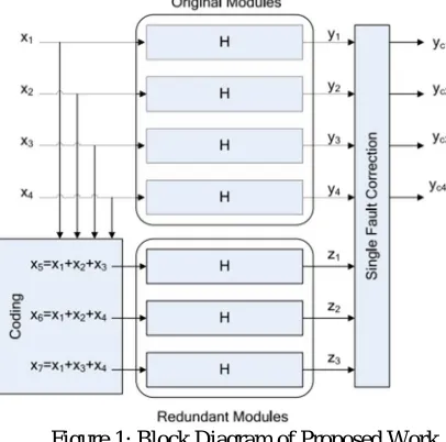
Figure 1: Block Diagram of Proposed Work
This ECC scheme can be applied to the parallel filters considered by defining a set of check filters zj. For the case of four filters y1, y2, y3, y4 and the Hamming code, the check filters would be z1[n] = y1[n] + y2[n] + y3[n] z2[n] = y1[n] + y2[n] + y4[n] z3[n] = y1[n] + y3[n] + y4[n] For example, an error on filter y1 will cause errors on the checks of z1, z2, and z3. Similarly, errors on the other filters will cause errors on a different group of zi . Therefore, as with the traditional ECCs, the error can be located and corrected.
A. Design Of Fir Filters
There are different methods for the design of FIR digital filter. The most common methods are
1) Fourier series method.
2) The window method
3) Frequency sampling method.
4) Optimal filter design method But we are designing the window method explained bellow
a) Window method: Several window functions have been proposed . Listed below are some of the most common:
i) Rectangular window
ii) Hanning window (also referred to as Hann)
iii) Hamming window
iv) Blackman window
v) Kaiser window
To reduce the oscillations in Fourier series method, the Fourier coefficients are modified by multiplying the infinite impulse response by a finite weighing sequence w (n) called a window. Windows are characterize by the main lobe width which is the bandwidth between first negative and first positive zero crossing, and by their ripple ratio. The main lobe width and the ripple ratio should be as low as possible; i,e the spectral energy of the window should be concentrated as far as possible in the main lobe and the energy in the side lobes should be as low as possible.
Two desirable characteristics of a window function are;
Fourier transform of the window function should have a small width of the main lobe.
Fourier transform of the window function should have side lobes that decrease in energy rapidly as / tends to 0.
Technology (IJRASET)
window’s characteristics.The Kaiser window is a kind of two parameter window function. In a Kaiser window width of main lobe can be controlled by
adjusting the length of the filter and side lobe level can be controlled by varying the other parameter α. But the Kaiser window has
the disadvantage of higher computational complexity due to the use of Bessel functions in the calculation of the window coefficients.
In this window function the width of main lobe can be varied by changing the value of α for a fixed length of the filter. α is selected
according to different applications. This generalized window is referred to as the Hamming window for α = 0.54 and Hanning
window for α= 0.5. They are both commonly used in speech processing and other digital signal processing applications. But in some
application such as spectral analysis of a specified frequency spectrum, if the frequency of interest contains two or more signals very near to each other, then frequency resolution is very important.
In such cases a small main lobe width of the window function in frequency domain is required. For an efficient value of α, this
window function provides a lesser main lobe width compares to Hanning (α = 0.5) and Hamming window (α= 0.54), however the
amplitude of side lobe and ripples in pass band is also increased
V. SIMULATION RESULTS
[image:5.612.57.565.466.672.2]Figure5.1: Main Block Simulation Result
Figure 5.1 explains the simulation results of main block in which input=1111111111111111, Output=1111111111111111.
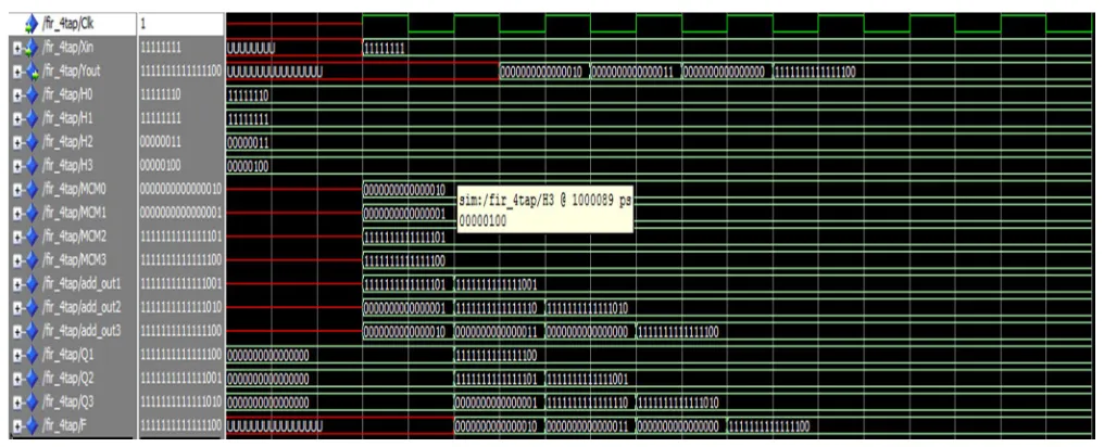
Figure 5.2 FIR filter simulation Result
Technology (IJRASET)
Figure 5.3 Encoder Simulation Result
[image:6.612.66.547.256.436.2]Figure 5.3 explains the encoder simulation result is shown in above, here we are giving 8 bit input as 11111111 then it encodes the data and it will generate two parity bits for 8 bit input i.e. 1111011110.it will give 10 bit output for 16 bit it will generate 4 parity bits then it will give 20 bit output.
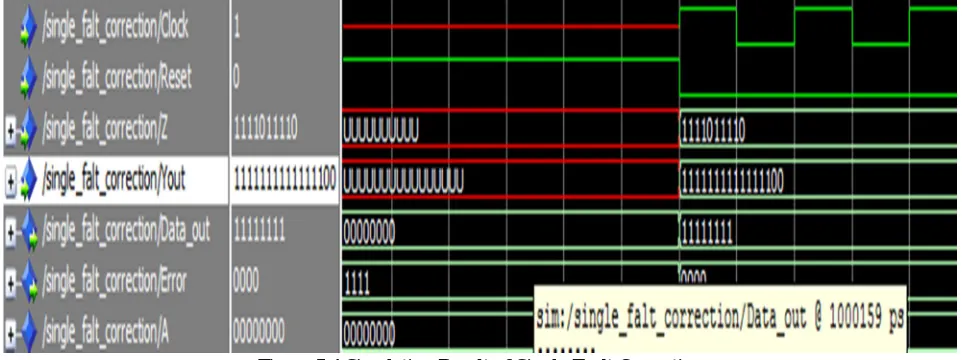
Figure 5.4 Simulation Result of Single Fault Correction
Figure 5.4 Input (z) =1111011110 , Input(Y out) =111111 1111111100 Output=11111111. Single fault correction simulation result is shown in above here we are giving 16 bit FIR filter and 10 bit encoder output as input then it will compare both data then it will give the original 8 bit (16 bit) data as output.
VI. CONCLUSION
This brief has presented a new scheme to protect parallel filters that are commonly found in modern signal processing circuits. The approach is based on applying ECCs to the parallel filters outputs to detect and correct errors. The scheme can be used for parallel filters that have the same response and process different input signals. The technique provides larger benefits when the number of parallel filters is large.
The proposed architecture can be easily used to implement high order FIR filters e.g. 20-tap with different coefficients word length without suffering from large architecture reconstruction and with low hardware complexity needed for the design. The proposed scheme can also be applied to the IIR filters. The future work is to perform a VLSI implementation of pulse shaping FIR filter for ultra wideband communications.
REFERENCES
[1] Reddy and P. Banarjee “Algorithm-based fault detection for signal processing applications,” IEEE Trans. Comput., vol. 39, no. 10,pp. 1304–1308, Oct. 1990. [2] T. Hitana and A. K. Deb, “Bridging concurrent and non-concurrent error detection in FIR filters,” in Proc. Norchip Conf., 2004,pp. 75–78.
[3] M. Nicolaidis, “Design for soft error mitigation,” IEEE Trans. DeviceMater. Rel., vol. 5, no. 3, pp. 405–418, Sep. 2005.
[4] B. Shim and N. Shanbhag, “Energy-efficient soft error-tolerant digital signal processing,” IEEE Trans. Very Large Scale Integr.(VLSI) Syst.,vol. 14, no. 4, pp. 336–348, Apr. 2006.