Low Power Approach for Fir Filter Using
Modified Booth Multiprecision Multiplier
Gowridevi.B1, Swamynathan.S.M2, Gangadevi.B3 1,2
Department of ECE, Kathir College of Engineering
3
Department of ECE, Kumaraguru college of Technology
Abstract— This paper presents an efficient approach to the design of low power reconfigurable finite impulse response (FIR) filter. The approach is well suited when the filter order is fixed and not changed for particular applications, and efficient trade-off between power savings and filter performance can be made using the proposed architecture. Generally, FIR filter exhibits more computational power consumption because of the multiplier unit. The proposed FIR filter dynamically changes the precision of multiplication with respect to the information available in the input data using Amplitude Detection (AD) block. Modified Booth Multi-Precision (MBMP) Multiplier is designed to accommodate low power and multiprecision operation. Also, reducing the computational complexity of multiplier unit tend to reduce the total power consumption of FIR filter. Simulation results show that the proposed approach achieves significant power savings without seriously compromising the filter performance.
Keywords— Finite Impulse Response (FIR), Amplitude Detection (AD), Modified Booth Multi-Precision (MBMP), Computational complexity, Power consumption
I. INTRODUCTION
The growth of mobile computing and portable multimedia applications has increased the demand for low power digital signal processing (DSP) systems. One of the most widely used operations performed in DSP is finite impulse response (FIR) filtering [1]. The input-output relationship of the linear time invariant (LTI) FIR filter can be expressed as the following equation:
N-1
y(n) = ∑ ck x(n-k) (1)
k=0
Where N represents the length of FIR filter, ck the k
th
coefficient, and x(n-k) the input data at time instant n-k . In many applications, in order to achieve high spectral containment and/or noise attenuation, FIR filters with fairly large number of taps are necessary. Nowadays, many finite impulse response (FIR) filter designs aimed at either high speed or reduced power consumption are developed. Many previous efforts for reducing power consumption of FIR filter generally focus on the optimization of the filter coefficients while maintaining a fixed filter order [2]–[4]. In that approaches, FIR filter structures are simplified to add and shift operations, and minimizing the number of additions/subtractions is one of the main goals of the research. However, one of the drawbacks encountered in those approaches is that once the filter architecture is decided, the coefficients cannot be changed; therefore, those techniques are not applicable to the FIR filter with programmable coefficients [1].
In [5], filter order varies according to the stop-band energy of the input signal. However, the approach suffers from slow filter-order adaptation time due to energy computations in the feedback mechanism. Previous studies in [6] show that sorting both the data samples and filter coefficients before the convolution operation has a desirable energy-quality characteristic of FIR filter. However, the overhead associated with the real-time sorting of incoming samples is too large. Reconfigurable FIR filter architectures are previously proposed for low power implementations [7]–[9] or to realize various frequency responses using a single filter [10].In this paper, we propose a simple yet efficient low power reconfigurable FIR filter architecture, where the the precision of multiplication dynamically changes with respect to the information available in the input data using Amplitude Detection (AD) block. In other words, when the data sample (8 bit) multiplied to the coefficient (32 bit) is so small, the multiplication operation can be simply reduced to 8 bit x 32 bit multiplication.
paper is organized as follows. In Section II, the basic idea of the proposed reconfigurable filter is described. Section III presents the MBMP multiplier architecture. Section IV discuss on the FIR filter simulation results and performance improvements. Section V deal with the conclusion part.
II. RECONFIGURABLEFIRFILTER
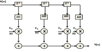
[image:3.612.231.390.208.267.2]As shown in Fig. 1, FIR filtering operation performs the weighted summations of input sequences, called as convolution sum, which are frequently used to implement the frequency selective low-pass, high-pass, or band-pass filters [1]. Generally, the amount of computation and the corresponding power consumption of FIR filter are directly proportional to the filter order and high computational effort of multiplier. If we can dynamically change the precision of multipliers, significant power savings can be achieved.
Fig. 1 Architecture of the direct form FIR filter
Fig. 1 shows the direct form of FIR filter in which the output is obtained by performing the concurrent multiplications of individual delayed signals and respective filter coefficients, followed by accumulation of all the products. Fig.2 shows the proposed direct form FIR architecture.
Fig. 2 Architecture of the Proposed FIR filter
The proposed architecture follows the direct form implementation which includes 4 tap delays and Amplitude Detector (AD) block. Precision of multiplication varies from 32 bit to 8 bit based on the information available in the input data. Because of the decreased delay elements, the order of filter is reduced to 3 and power consumption is reduced due to the lower precision multiplication. In the fixed point arithmetic of FIR filter, full operand bit widths of the multiplier outputs is not generally used. In other words, as shown in Fig. 2, when the bit-widths of data inputs and coefficients are 32, the multiplier generates 64-bit outputs. However, considering the circuit area of the following multipliers, the LSBs of input data are usually truncated or rounded off, (e.g., 8, 16 or 24 bits are used) which incurs quantization errors. If we can carefully select the input and coefficient amplitudes such that the multiplication of those two numbers is as small as the quantization error, filter performance degradation can be made negligible.
A. Amplitude Detector Block
In order to monitor the amplitudes of input samples and change the right multiplication operations, amplitude detector (AD) in
Fig. 4 is used. When the absolute value of x(n) is smaller than the threshold xth , the output of AD is set to “1”. The design of
AD is dependent on the input threshold xth, where the fan-in’s of AND and OR gate are decided by xth. A single amplitude
detector block consists of three small AD blocks named as AD1, AD2 and AD3. AD block is made up of AND, OR and XNOR gates. AD1 block is set to 1 when the input data contains 0’s in the first 24 bit of MSB and it takes care of producing valid information part (8 bit LSB) to the multiplier block.
[image:3.612.230.394.328.412.2]Fig. 4 Architecture Amplitude Detector
AD2 block is responsible to detect the input data contains 0’s in the first 16 bit of MSB and it takes care of 16 bit multiplication.
Similarly, AD3 block is set to 1 when the input data contains 0’s in the first 8 bit of MSB and it takes care of producing valid
information part (24 bit LSB) to the multiplier block.
III.MBMPMULTIPLIER
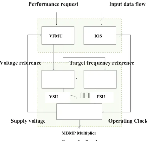
The proposed MBMP multiplier system (Fig. 1) comprises five different modules that are as follows: The MBMP multiplier.
The input operands scheduler (IOS) whose function is to select the input data stream which is helpful to perform an appropriate multiplication operation as per the application requirement.
The frequency scaling unit is to generate the required operating frequency of the multiplier.
The voltage scaling unit (VSU) implemented using a razor based voltage dithering technique. Its function is to dynamically generate the supply voltage so as to minimize power consumption;
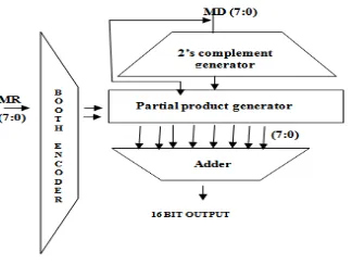
The dynamic voltage/frequency management unit (VFMU) that receives the user requirements (e.g., throughput). It sends control signals to the VSU and FSU to generate the required power supply voltage and clock for the MBMP multiplier. The modified booth multiplier produces N/2 partial products, each of which depends on bits of the multiplier. In this paper, we are aiming to build up a booth encoding for multiprecision multiplier. Modified booth encoding allows higher radix parallel operation. Fig.6 illustrates the architecture of modified booth 8 bit multiplier. The 16 bit product output is obtained from two 8 operands namely multiplicand (MD) and multiplier (MR).The architecture comprises four parts: 1) Booth encoder, 2) 2’s complement generator, 3) Partial product generator, 4) Adder. Booth encoder is responsible to make three bit blocks of 8 bit multiplier starting from MSB to LSB. Hence, partial products are chosen by considering a pair of bits along with the most significant bit (MSB) from the previous pair.
Performance request Input data flow
Voltage reference Target frequency reference
.
Supply voltage Operating Clock
Error feedback
VFMU IOS
VSU FSU
[image:4.612.176.424.467.706.2]pair is true, the current partial product is selected to be negative and the next partial product is incremented. Since it is a 8 bit(N) multiplier, totally four partial products (N/2) have been generated. to be negative and the next partial product is incremented. Since it is a 8 bit (N) multiplier, totally four partial products (N/2) have been generated. The final 16 bit output is obtained by adding the partial products using adders. Table 1 shows how the partial products are generated by taking the 2’s complement of
the multiplicand (possibly left-shifted by one column).
Fig. 6 Modified Booth 8 bit multiplier architecture.
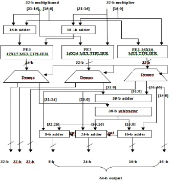
The multiprecision concept is illustrated in Fig. 7. The 3 bit mode control indicates whether to perform a 32 or 16 or 8 bit multiplication. Depending on the selection mode the 32 bit input stream is given among the PEs (Processing Element) to perform the computation [1]. Fig. 3 shows how three 16 bit PEs are used to implement a 32 x 32 bit multiplier. Whenever the full precision (32x 32 bit) is not done, the supply voltage and clock frequency can be scaled down according to the actual
[image:5.612.225.387.150.272.2]workload. We define X and Y as the 2n-bits wide multiplicand and multiplier, respectively.
TABLE I
MODIFIED BOOTH ENCODING TABLE
XH, YH are their respective n most significant bits whereas XL, YL are their respective n least significant bits. XLYL, XHYL, XLYH
and XHYH is the crosswise products. The product of X and Y can be expressed as follows:
where XHYL + XLYH reconfigurable multiplier can be built using adders and four n bit x n bit multipliers to compute XHYH, XL
YL, XLYH and XHYL. However, this would result in overheads of silicon area and power. So, we can define that,
then (1) could be rewritten as follows: Multiplier bits block
Partial
Products Action to be done
0 0 0 0 Do nothing
0 0 1 1* MD Multiply 1 with Multiplicand
0 1 0 1* MD Multiply 1 with Multiplicand
0 1 1 2* MD Left shift Multiplicand once
1 0 0 -2* MD Subtract & Left shift multiplicand
once
1 0 1 -1* MD Subtract Multiplicand
1 1 0 -1* MD Subtract Multiplicand
Fig. 7 Three PEs combined to form 32 x 32 bit multiplier.
Comparing (1), (4), w have removed one n x n bit multiplier (for calculating or ) and one 2n-bit adder (for
calculating ). The two adders are replaced with two n- bit adders and two (2n+2) bit subtractor. We actually need
two 16 x 16 multipliers (for calculating and ) and 1 17 x 17 bit multiplier (for calculating ).
[image:6.612.228.398.75.257.2]IV. SIMULATIONRESULTSANDDISCUSSION
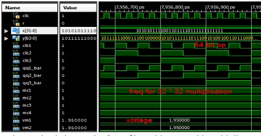
Fig.8 shows the simulation results of FIR filter in which 8*32 bit multiplication is done to produce the 64 bit output. Based on the amplitude detection block “AD1”or “AD2” or “AD3”, MBMP multiplier will perform 8 bit or 16 bit or 24 bit or 32 bit computation respectively. The voltage and frequency are consumed as per the current workload. In Fig.8, 8 * 32 bit multiplication operation is performed in parallel manner as the given amplitude detection is “AD1”. In case of 8 *32 bit multiplication, the frequency and voltage are scaled down to 12.5 MHz and 0.95 V from the total operating frequency 50 MHz and supply voltages. Hence the power consumption for 8 * 32 bit multiplication is 52 mW which is an optimum value. The required simulation has been carried out using ISIM Simulator and the functional verification performed.
Fig. 8 Simulation result of FIR filter with 8 x 32 bit multiplier
[image:6.612.182.442.430.548.2] [image:6.612.181.440.597.706.2]on the amplitude detection block AD3, MBMP multiplier will perform 24 bit * 32 bit computation respectively. The voltage and frequency are consumed as per the current workload.
Fig.10 Simulation result of FIR filter with 24 x 32 bit multiplier
[image:7.612.177.443.328.467.2]Fig.11 shows the output waveform of modified booth 32 * 32 multiplier in which 64 bit product output is obtained. Frequency of 100MHz and 1.95 V are required for 32 bit multiplication.
Fig. 11 Simulation result of FIR filter with 32 x 32 bit multiplier
The performance of FIR filter is discussed in Table 2. The analysis is done with respect to the power and frequency consumption of 8 bit, 16 bit, 24 bit and 32 bit multiplication operation. From Table 2, the 32 bit multiplier consumes 60mW power with optimum frequency 100 MHz. Similarly the power & frequency consumption of FIR filter based on 16 bit and 8 bit multipliers are shown in the table 2. Table III illustrates the total area consumed by different precision multipliers in terms of number of slices and LUTs. Also, delay (ns) values are given for 8, 16, 24 and 32 bit multiplier.
TABLEII
POWER &FREQUENCY COMPARISON OF FIR FILTER WITH DIFFERENT PRECISION MULTIPLIERS
FIR filter with various Multiplier Schemes
Frequency (MHz)
Power Consumption
(mW)
8 *32 Multiplier 12.5 52
16 *32 Multiplier 25.0 55
24 *32 Multiplier 50.0 57
TABLEIII
AREA AND DELAY COMPARISON OF FIRFILTER WITH MULTIPRECION MULTIPLIERS
FIR filter with various Multiplier Schemes
Area in Slices in LUTs
Delay (ns)
8 * 32 Multiplier 101 186 32.052
16 * 32 Multiplier 523 938 99.748
24 * 32 Multiplier 745 1025 249.345
32 * 32 Multiplier 1643 3079 396.713
V. CONCLUSION
We proposed a novel FIR filter architecture featuring with low power consumption compared with conventional direct form FIR filter counterpart. When integrating this MBMP multiplier architecture with a DVS, DFS approach and a novel operands scheduler, run time adaptation to the actual workload can be achieved. Also it can operate at the minimum supply voltage and minimum frequency level while meeting the throughput requirements. It is to be concluded that the proposed FIR filter with MBMP multiplier performs better in terms of area, delay and power consumption.
REFERENCES
[1] Ji-Woong Choi, Seon Wook Kim, and Jongsun Park, Seok-Jae Lee“Reconfigurable FIR Filter Architecture to Trade Off Filter Performance for Dynamic Power Consumption” IEEE Trans.Very Large Scale Integr. (VLSI) Syst., Sep 2010.
[2] H. Samueli, “An improved search algorithm for the design of multiplierless FIR filter with powers-of-two coefficients,” IEEE Trans. Circuits Syst., vol. 36, no. 7, pp. 1044–1047, Jul. 1989.
[3] R. I. Hartley, “Subexpression sharing in filters using canonical signed digit multipliers,” IEEE Trans. Circuits Syst. II, Analog Digit. Signal Process., vol. 43, no. 10, pp. 677–688, Oct. 1996.
[4] O. Gustafsson, “A difference based adder graph heuristic for multiple constant multiplication problems,” in Proc. IEEE Int. Symp. Circuits Syst., 2007, pp. 1097–1100.
[5] Ludwig, H. Nawab, and A. P. Chandrakasan, “Low power digital filtering using approximate processing,” IEEE J. Solid-State Circuits,vol. 31, no. 3, pp. 395–400, Mar. 1996.
[6] Sinha, A. Wang, and A. P. Chandrakasan, “Energy scalable system design,” IEEE Trans. Very Large Scale Integr. Syst., vol. 10, no. 2, pp.135–145, Apr. 2002.
[7] K.-H. Chen and T.-D. Chiueh, “A low-power digit-based reconfigurable FIR filter,” IEEE Trans. Circuits Syst. II, Exp. Briefs, vol. 53, no. 8, pp. 617–621, Dec. 2006.
[8] R. Mahesh and A. P. Vinod, “New reconfigurable architectures for implementing filters with low complexity,” IEEE Trans. Comput.-Aided Des. Integr. Circuits Syst., vol. 29, no. 2, pp. 275–288, Feb. 2010.
[9] Z. Yu, M.-L. Yu, K. Azadet, and A. N. Wilson, Jr, “A low power FIR filter design technique using dynamic reduced signal representation,” in Proc. Int. Symp. VLSI Tech., Syst., Appl., 2001, pp. 113–116.
[10] R. Mahesh and A. P. Vinod, “Coefficient decimation approach for realizing reconfigurable finite impulse response filters,” in Proc. IEEE Int.Symp. Circuits Syst., 2008, pp. 81–84.