A Reliable Adder Circuit with Voter Element for
Fault Detection and Correction using Reversible
Gates
Ganivada Srinivas Rao1 , Male Srinivasa Rao2
1,2
Department of Electronics and Communication Engineering Avanthi’s Saint Theressa Institute of Engineering and Technology, Garividi, India
Abstract: Design of a fault-tolerant Full adder circuit using reversible logic gates can be done using Triple Modular Redundancy (TMR) with voting element. This system consists of Three Identical (Redundant) modules connected in parallel whose output is connected to a majority voter element. The voter circuit used in the TMR system must be fault free; otherwise it will nullify the gains of the redundancy scheme. In this paper, a novel full adder circuit design using reversible logic gates, so that it can be easily used for N-modular redundancy (NMR). Simulations are carried out using Xilinx 10.2 and Model Sim Keywords: Fault tolerance, NMR, Reversible logic, TMR, voter element.
I. INTRODUCTION
In this paper a fault tolerant full adder circuit design is proposed using reversible logic gates with TMR redundancy with majority voter element which can produce the correct output in presence of fault in any module and also detects the faulty module. A voter element is used to determine possible correct result through the majority vote. Failure of the voter circuit results in failure of the TMR system, while failure of one module can be tolerated. Therefore, a fault-tolerant voter will improve the reliability of the system significantly. In an NMR system, number of faulty modules that can be identified is equal to (N-1)/2 where N is the number of redundant modules.
II. TRIPLEMODULARREDUNDANCYWITHMAJORITYELEMENT
The basic modular redundancy circuit is triple modular redundancy (TMR)[1], shown in Fig. 1. TMR consists of three parallel digital components (modules), with equivalent logic. The same input is fed to the three modules and a voter gives the majority as the system output[2].
Fig.1 Triple modular redundancy Digital circuit A
Digital circuit C Digital circuit B
input Voter
If any two of the three modules in the TMR system work, assuming the voter does not fail, the system output will be correct. This equals the reliability of a two-out-of-three system.
III. DESIGNOFLOGICCIRCUITUSINGREVERSIBLEGATES
Reversible or information-lossless circuits have applications in digital signal processing, communication, computer graphics, cryptography and quantum computation. Landauer's principle[3] states that “logic computations that are not reversible necessarily generate kT * log 2 Joules of heat energy for every bit of information that is lost, where k is Boltzmann's constant and T the absolute temperature at which computation is performed.” A reversible logic circuit should have the following features:
A.Use minimum number of reversible gates
B.Use minimum number of garbage output
C.Use minimum number of constants
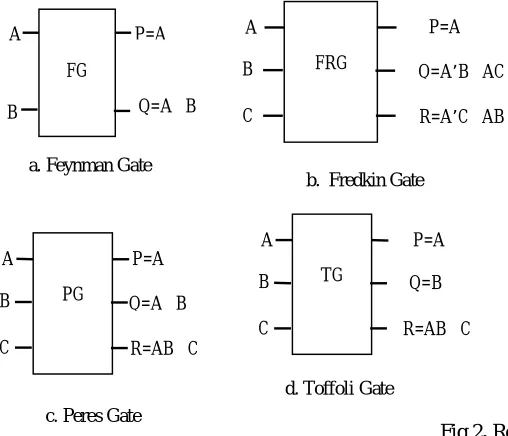
In open literature many 2x2, 3x3, 4x4 reversible gates and parity preserving gates are reported[4-5]. Few reversible logic gates are presented in fig 2.
Fig 2. Reversible logic gates
IV. 4X4REVERSIBLEADDERGATE
The proposed 4 X 4 Reversible Adder Gate (RAG) is shown in Fig. 3, corresponding truth table of RAG is shown in Table 1. It can be verified from the Truth Table that the input pattern corresponding to a particular output pattern can be uniquely determined. The proposed gate can implement all Boolean functions.
Fig 3. Reversible Adder Gate (RAG)
TABLEI TRUTH TABLE OF RAG
Inputs Outputs
A B C D P Q R S
0 0 0 0 0 0 0 1
0 0 0 1 1 0 0 1
FG A
B
P=A
Q=AB
a. Feynman Gate
FRG A
B
C
P=A
Q=A’BAC
R=A’CAB
b. Fredkin Gate
TG A B C P=A Q=B
R=ABC
d. Toffoli Gate PG
A
B
C
P=A
Q=AB
R=ABC
c. Peres Gate
RAG A
B
C
D
P = A B C D
Q = AB + BC + AC
R = A B
[image:3.612.47.301.251.469.2]0 0 1 0 1 0 0 0
0 0 1 1 0 0 0 0
0 1 0 0 1 0 1 1
0 1 0 1 0 0 1 1
0 1 1 0 0 1 1 0
0 1 1 1 1 1 1 0
1 0 0 0 1 0 1 0
1 0 0 1 0 0 1 0
1 0 1 0 0 1 1 1
1 0 1 1 1 1 1 1
1 1 0 0 0 1 0 0
1 1 0 1 1 1 0 0
1 1 1 0 1 1 0 1
1 1 1 1 0 1 0 1
V. MAJORITYVOTERGATE
The voting gate is a standard logic gate used in modeling fault-tolerant systems. In a Voter element the decision is made according to majority consensus at outputs of redundant modules to select the most reliable results [6]. It does not consider the functionality of redundant modules. Voter algorithm selects the most common output. In the Table 2, truth table of conventional bit-by-bit majority voting for Triple Modular Redundancy (TMR) is given. In this table, A,B,Care output of modules and Yrepresents voter output.
TABLEII
TRUTH TABLE OF MAJORITY VOTER ELEMENT
Input Output
A B C Y
0 0 0 0
0 0 1 0
0 1 0 0
0 1 1 1
1 0 0 0
1 0 1 1
1 1 0 1
1 1 1 1
VI. DESIGNOFREVERSIBLEVOTERGATE(RVG)
Basic Voter element makes decision according to the consensus at outputs of redundant modules to select the most reliable results. Conventional Voter element selects the majority of the outputs in a TMR system, but the user cannot identify the faulty module. The output of a voter element is valid in a NMR system till number of faulty modules are not more than (N-1)/2 where N is the number of modules in the system. With the proposed RVG it is possible to detect the faulty module and also the sub circuit in that module. Truth table to design the RVG is shown in table III.
TABLEIII
TRUTH TABLE OF REVERSIBLE VOTER GATE
Input Output A B C Q f1 f2
1 0 0 0 0 1 1 0 1 1 1 0 1 1 0 1 1 1 1 1 1 1 0 0
The outputs f1 and f2 are used to find the faulty module. If f1&f2 = “00” then all three modules are faulty free. If f1&f2 = “01”, then Module A is faulty. If f1&f2 = “10” then module B is faulty. If f1&f2 = “11” then module C is faulty. Following Boolean expressions are obtained by simplifying truth table III. Block diagram of Reversible Voter Gate is shown in Fig 4.
Q = (B and C) or (A and C) or ( A and B); f1 = B xor C;
[image:5.612.204.402.334.435.2]f2 = A xor C;
Fig 4. Reversible Voter Gate
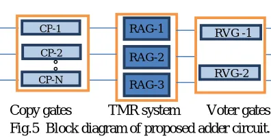
Basic idea of implementing the adder is shown in Fig. 5
Copy gates TMR system Voter gates Fig.5 Block diagram of proposed adder circuit.
Copying circuits(CP) CP-1 to CP-N are used to copy the inputs to apply same inputs to all the redundant modules (RM-1 to RM-3) since fan out is not allowed in reversible gates. For this purpose Feynman gates which are 2X2 gates are used to copy the input to the output by keeping the input B at logic low.
The redundant gates are used in TMR configuration. Since NMR system can handle (N-1) / 2 faulty modules the system can withstand one faulty module. Two RVG modules are used to correct the outputs of SUM and CARRY generated by each RAG module.
[image:5.612.174.417.541.713.2]VII.SCHEMATICDIAGRAM
Fig.6 Schematic diagram of proposed adder circuit
A
B f1 = (BC)
Q = (AB)+(BC)+(AC)
C f2 (AC)
RVG
CP-1
CP-2
RAG-1
RAG-3 RAG-2
RVG -1
RVG-2
Fig. 6 shows the schematic diagram of proposed adder circuit in which Fyenman gates are used to copy the inputs A, B, C and D to three Reversible Adder Gates (RAG). The three RAGs are connected such that TMR system is established. The two Voter Gates (voter) are used to correct the output and are also used to identify the faulty module and also sub-module in the redundant circuit Fault identification mechanism for above schematic is illustrated in Table. IV
TABLEIV
FAULT IDENTIFICATION MECHANISM
VIII.RESULTS
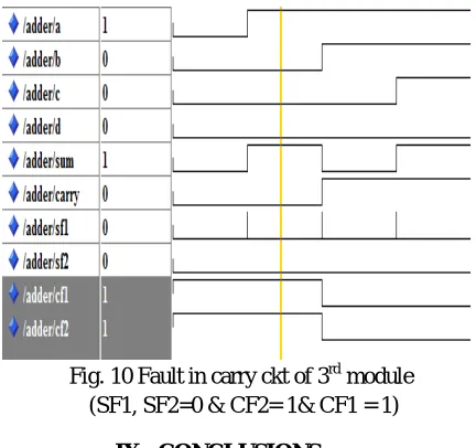
[image:6.612.205.420.582.713.2]Simulations are carried out using Xilinx 10.2 and ModelSim and the results are presented in Fig. 7. to Fig. 11. Fig. 7 shows the response of system when it is Fault free. Fig. 8 shows the response when there is Fault in carry ckt of 2nd module. Fig. 9 shows the response when sum ckt of 1st module and carry ckt of 2nd module is faulty. Fig. 10 show the response of the system when carry ckt of 3rd module is faulty.
Fig. 7 Fault Free Output (CF1, CF2,SF1, SF2 = 0) SF 1 SF 2 CF1 CF2 Faulty module and sub-circuit
0 0 0 0 No faults
0 0 0 1 Fault in carry ckt of 1st module
0 0 1 0 Fault in carry ckt of 2nd module
0 0 1 1 Fault in carry ckt of 3rd module 0 1 0 0 Fault in sum ckt of 1st module 0 1 0 1 1st module is faulty
0 1 1 0 Fault in sum ckt of 1st module and carry ckt of 2nd module
0 1 1 1 Fault in sum ckt of 1st module and carry ckt of 2nd module
1 0 0 0 Fault in sum ckt of 2nd module 1 0 0 1 Fault in sum ckt of 2nd module and
carry ckt of 1st module 1 0 1 0 2nd module is faulty
1 0 1 1 Fault in sum ckt of 2nd module and carry ckt of 3rd module
1 1 0 0 Fault in sum ckt of 3rd module 1 1 0 1 Fault in sum ckt of 3rd module and
carry circuit of 1st module
Fig. 8 Fault in carry ckt of 2nd module (SF1, SF2, CF2= 0& CF1 = 1)
[image:7.612.204.420.472.675.2]Fig. 9 Fault in sum ckt of 1st module and carry ckt of 2nd module (SF1= 0, SF2=1, CF2= 0& CF1 = 1)
Fig. 10 Fault in carry ckt of 3rd module (SF1, SF2=0 & CF2= 1& CF1 = 1)
IX. CONCLUSIONS
A. Conclusions
REFERENCES
[1] T. Ban, L.A. De Barros Naviner, A Simple Fault-Tolerant digital Voter circuit in TMR Nano Architectures. NEWCAS conference(NEWCAS), 2010 8th IEEE
International,pp. 269-272 June 2010.
[2] Fault tolerant Computer system based on TMR Architecture, Liberios Vokorokos, Brainslav Mados, Jan Perhac, 5th Slovakian-Hungarian Joint Symposium on Applied Machine Intelligence and Informatics, January 25-26, 2007
[3] R.Landauer, “Irreversibility and Heat Generation in the Computational Process”, IBM Journal of Research and Development, 5,pp. 183-191,1961. [4] E. Fredkin, T Toffoli, “Conservative Logic”, International Journal of Theory. Physics, 21(1982),pp.219-253.
[5] T. Toffoli., “Reversible Computing”, Tech memo MIT/LCS/TM-151, MIT Lab for Computer Science (1980).
[6] Majority-based reversible logic gates, Guowu Yang, William N.N. Hung, Xiaoyu Song, Marek Perkowski, Theoretical Computer Science, Elsevier, 334(2005), 259-274.
AUTHORS
Sri. Male Srinivasa Rao, M.Tech from JNTU College of Engineering, Kakinada, He is presently working as Assistant professor & Head, Dept. of ECE in Avanthi’s Saint Theressa Institute of Engineering and Technology, Garividi, Vizianagaram. Published various technical papers in National/International Journals / Conferences. His research interests include EMI/EMC, VLSI and Embedded Systems.