IJEDR1402236
International Journal of Engineering Development and Research (www.ijedr.org)2774
A CT Saturation Detection Algorithm Using
Secondary Current Third Difference Function
1
R. P. Pandey,
2Dr. R. N. Patel
1PG Student [PSE], 2Professor
Department of EEE, SSTC Bhilai Chhattisgarh, India
_______________________________________________________________________________________________________
Abstract - This paper proposes an algorithm for detecting current transformer (CT) saturation by analyzing a secondary current. The current has point of inflection where saturation begins and ends. Then, discontinuity in the first difference of the current arises at the next instants of points of inflection, where the second and third differences of the current may have large values enough to detect saturation. In this paper third difference is used because it is more effective than second difference in terms of saturation detection. Ideally the function of current transformer is to transform and reproduce the primary current in the secondary circuit in a most faithful manner. Practically, some distortion in ratio and phase angle can be tolerated. How much of these distortions can be tolerated depend upon the application for which the CT is being used. These allowable errors are specified in different standards. Under normal operating conditions CT reproduces the primary current in the secondary side with good degree of accuracy, however, during abnormal operating conditions CT is likely to get saturated. A current transformer (CT) can saturate, for various reasons, like: attempting to transform heavy primary fault currents, heavy burden on the secondary side of current transformer or transient DC offset in the primary fault current. The method for CT saturation detection that has been simulated is, An algorithm for detecting CT saturation using second current third difference function.
Keywords - Current Transformer Saturation, difference, point of inflection, remanent flux
________________________________________________________________________________________________________
I.INTRODUCTION
Current transformers used for feeding the protective relays form a vital link in any protective system. The successful operation of the relay entirely depends upon the ability of the CT to faithfully transform the fault current waveforms. In an ideal condition, the CT would do its job with 100% fidelity and we would not be bothering about i t a t a l l. However, in t h e r e a l s it u at ion CTs p res ent t he i r own p r o b l e m s.The major problem is the tendency of the CT to saturate during the fault i.e., the very time during which it is expected to operate with high degree of fidelity. Thus, researchers are always searching for newer and better methods of mitigating the effect of CT saturation. If we are successful in mitigating these problems than it can result in substantial saving in cost of the CT. Thus there is a strong motivation for improving the performance of conventional CTs. In electrical transmission s y s t e ms, s a t u r a t ion o f c u r re n t t r a n s f o r m e r s at h i g h fault currents m a y cause mal-operation of r e l a y s .In this paper, investigates the transient behavior of current transformer with heavy primary currents and also effect of DC offset (which is a function of switching instants and X/R ratio). This paper proposes a CT saturation detection algorithm based on the third difference of a secondary current. However, an antialiasing low-pass filter softens the current and, thus, reduces the values of the third difference at the next samples of the points of inflections. There are several techniques in the literatures intended for detecting and compensating the CT secondary current. Ref [1] proposes a CT saturation detection algorithm based on the third difference of a secondary current. It is based on the fact that in the first difference of the current, discontinuity arises at the next samples of the points of inflection (i.e., next samples of the saturation beginning/end); consequently, the third difference at those instants is much larger than the magnitude of a sinusoid before/during saturation. A method is proposed for detecting the saturation instant depending on converting the three phase currents to space phasors [2]. In the unsaturated state their trajectories are circles and deviation from this characteristic indicates saturation of CT. An impedance based CT saturation algorithm for bus bar differential protection is proposed in [3].During saturation, the secondary current is assumed to be zero and the impedance measured becomes infinity. For verifying this result, the magnetizing curve of CT is assumed parallel to horizontal axis during saturation.
II.SITUATIONSDUETOWHICHCTGETSSATURATED
The MATLAB model of the CT‟s will be utilized to demonstrate the effects of following factors: 1. Secondary burden and accuracy class and their effects on CT‟s saturation.
IJEDR1402236
International Journal of Engineering Development and Research (www.ijedr.org)2775
III.SIMULATIONCIRCUIT
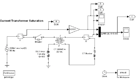
Figure 1 Current transformer saturation simulation circuit
Circuit description
A current transformer (CT) is used to measure current in a shunt inductor connected on a 220 kV network. The CT is rated 2000 A / 5 A, 25 VA. The primary winding which consists of a single turn passing through the CT toroidal core is connected in series with the shunt inductor rated 69.3Mvar, 69.3kv.The secondary winding consisting of 1*2000/5 = 400 turns is short circuited through a R-L burden load resistance.
IV.EFFECTOFCT’S BURDENONITSSATURATION
The burden of a current transformer, as defined in IEEE C37-110, is the property of the circuit connected to the secondary winding that determines the active and reactive power at the secondary terminals. The burden is expressed either as total ohms impedance, together with the effective resistance and reactance components, or as the total volt-amperes and power factor of the secondary devices and leads at the specified values of frequency and current. The accuracy of CT‟s is defined by IEEE C37-110-1996, as the extent to which the current in the secondary circuit reproduces the current in the primary circuit in the proportion stated by the marked ratio, and represents the phase relationship of the primary current. The accuracy class can be obtained by calculations or by test. The test will determine the minimum secondary terminal voltage that transformer will produce at 20 times rated secondary current with one of the standard burdens without exceeding the 10% accuracy class limit.
Figure: 2 Primary and secondary current of the CT at moderate burden on 100 Ω
0.85 0.9 0.95 1
-3000 -2000 -1000 0 1000 2000 3000
time(sec)
CT
Cu
rre
nt
(A
mp
)
CT Saturation Characteristics
IJEDR1402236
International Journal of Engineering Development and Research (www.ijedr.org)2776
Figure: 3 Primary current of the CT at moderate burden on 100 ΩFigure: 4 Secondary current of the CT at moderate burden on 100 Ω
Figure: 5 Primary line current of the CT at moderate burden on 100 Ω
V.EFFECTOFSHORTCIRCUITLEVELONCTPERFORMANCE
In general, CT ratios are selected to match the maximum load current requirements, i.e., the maximum design load current should not exceed the CT rated primary current. The highest CT ratio permissible should usually be used to minimize wiring burden and to obtain the highest CT capability and performance. The CT should be large enough so that the CT secondary current does not exceed 20 times the rated current under symmetrical primary fault current. The use of low ratio CT‟s on circuits of rated current where fault current levels are very high, presents problems of reduced CT capability. These problems can be minimized by using the highest CT ratio that is compatible with low current relays and instruments. In this analysis, the
0.85 0.9 0.95 1
-8 -6 -4 -2 0 2 4 6 8
time(sec)
CT
Cu
rre
nt
(A
m
p)
CT Saturation Characteristics
0.85 0.9 0.95 1
-3 -2 -1 0 1 2 3
time(sec)
CT
Cu
rre
nt
(A
m
p)
CT Saturation Characteristics with Burden of 100
0.85 0.9 0.95 1
-3000 -2000 -1000 0 1000 2000 3000
time(sec)
CT
Cu
rre
nt
(A
mp
)
CT Saturation Characteristics
IJEDR1402236
International Journal of Engineering Development and Research (www.ijedr.org)2777
behaviour of the CT‟s will be examined, considering the standard burden, to show its performance under various symmetrical short circuits.Figure: 6 Saturation at lower primary short circuit current
Figure: 7 Saturation due to larger primary short circuit current
VI.ALGORITHM FOR DETECTING CT SATURATION USING SECOND CURRENT THIRD DIFFERENCE
FUNCTION
Figure: 8 Simplified equivalent circuit of a CT for transient analysis.
The above fig shows a simplified equivalent circuit of a CT for transient analysis. The primary current can be set as i2(t) = Imax[cos(ωt- θ)-e(-t/Tp)cos(θ) for t ≥ 0 ………(1)
0 for t <0
Where Imax, Tp and θ are the maximum fault current, the primary time constant, and a fault inception angle, respectively. The secondary current of a CT can be given by[1]
i2(t) = A*e-t/Ts + B*e-t/Tp –C*sin(ωt-θ-φ)………(2)
Where Ts is the secondary time constant and tanψ=ωTs It consists of the two exponentially decaying terms and one sinusoidal term. The first and second terms exponentially decay with Ts and Tp, respectively. On the other hand, the magnitude of a sinusoid C is given by
√ ( ) ……….(3)
Thus, C cannot exceed Imax. The discrete-time version of i2(t) can e obtained by letting t=Nt
[ ]
( ) ……(4)
Defining the first difference of i2(n) yields [ ] [ ] [ ]
( )
( )
( ) ( ) .…… (5)
Now the second and third difference of i2[n] given del2[n]=del1[n]-del1[n-1] .……(6)
del3[n]=del2[n]-del2[n-1] ...…..(7)
IJEDR1402236
International Journal of Engineering Development and Research (www.ijedr.org)2778
CT saturation. In this method third difference is used because it is more effective than the second difference in terms of saturation detection.VII.RESULTANDDISCUSSION
Criteria for CT Saturation Detection
Either del2[n] or del3[n] can be used as a saturation detector depending on C and N. As the values of del3[n] at the next instants of the saturation beginning/end are much larger than[2sin (π/N)]3C. Equation (8) is used as the criteria for saturation detection. The instants satisfying (8) are detected and then the beginning and the end are classified according to the former state del3 [n]> Th …….. (8)
Where Th is the threshold value and can be determined using
√ * ( )+ .…….(9)
Where If max is the expected maximum fault current and is a margin factor considering the effect of a low-pass filter and the sensitivity of the algorithm. The above result is based on synchronism at the saturation beginning/end between sampled current and original currents. However, under practical conditions, del3[n] may have larger values than the threshold value at some samples after the next instant of the saturation beginning/end, which has resulted due to asynchronism at the beginning/end of saturation[10].
In the Case of a Very Small Time Constant During Saturation
If the magnetization inductance in a saturated region is very small, the current during saturation is in the form of only ex-ponential term, which collapses to zero with a very small time constant as soon as a CT saturates. Then, the exex-ponential term inis reduced less than the case of a large time constant. As the time constant is smaller, the reduction rate is larger. Con-sequently, there exists exponential terms remaining in and during saturation. The values of might be larger than the threshold value at several samples after the be-ginning as well as the next instant of the beginning. Therefore, the detector should keep the former state in those samples even though (8) is satisfied. Since the saturation end is also a point of inflection, at the next instant of the end has a larger value than the threshold value. The same criteria of (8) can be used for detection in this case. Thus, the proposed algorithm can detect saturation even though a current collapses to zero with a very small secondary time constant as soon as a CT saturates[10].
Figure: 9 a)secondary currents ; b)del1[n]; c) del2[n] ; d)del3[n]
VIII.CONCLUSION
IJEDR1402236
International Journal of Engineering Development and Research (www.ijedr.org)2779
REFERENCES[1] Yong-Cheol Kang, Seung-Hun Ok, Sang-Hee Kang, A CT saturation detection algorithm, IEEE Trans. Power Deliv. 19 (January (1)) (2004) 78–85.
[2] G. Hosemann, H.M. Steigerwald, Model saturation detector for digital differential protection, IEEE Trans. Power Deliv. 8 (July (3)) (1993) 933–940.
[3] C. Fernandez, An impedance-based CT saturation detection algorithm for bus-bar differential protection, IEEE Trans. Power Deliv. 16 (October (4))(2001) 468–472.
[4] Jiuping Pan, Khoi Vu, Yi Hu, An efficient compensation algorithm for current transformer saturation effects, IEEE Trans. Power Deliv.19 (October (4)) (2004)1623–1628.
[5] Yong Cheol Kang, Ui Jai Lim, Sang-Hee Kang, Peter A. Crossley, Compensation of the distortion in the Secondary current caused by saturation and remanence in a CT, IEEE Trans. Power Deliv. 19 (October (4))(2004)1642–1649. [6] Y.C.Kang, J.K. Park, S.H.Kang, A.T. Johns, R.K.Aggarwal, An algorithm for compensating secondary current of
Current transformers, IEEE Trans.Power Deliv. 12 (January) (1997) 116–124.
[7] K. El-Naggar and M. Gilany, “A discrete dynamic filter for detecting and compensating ct saturation,” Electric Power Systems Research, vol. 77, no. 5-6, pp. 527–533, April 2007.
[8] N. Villamagna and P. A. Crossley, “A CT saturation detection algo-rithm using symmetrical components for current differential protection,” IEEE Trans. Power Del., vol. 21, no. 1, pp. 38–45, Jan. 2006.
[9] N. Locci and C. Muscas, “A digital compensation method for improving current transformer accuracy,” IEEE Trans. Power Del., vol.15, no.4, pp. 1104–1109, Oct.
[10] IEEE Guide for the Application of Current Transformers Used for Protective Relaying Purposes, ANSI/IEEE C37.110 Std.
[11] IEEE C57.13-1993 Standard Requirements for Instrument Transformers.
[12] Y. C. Kang, U. J. Lim, S. H. Kang, and P. A. Crossley, “Compensation of the distortion in the secondary current caused by saturation and remanence in a CT,” IEEE Trans. Power Del., vol. 19, no. 4, pp. 1642 1649, Oct. 2004. [13] D.A. Bradely, C.B.Gray and D.O‟Kelly, “Transient compensation of Current transformers”IEEE Trans.Power
Apparatus and Systems,vol.97 no.4,pp. 1264-1271 July-Aug. 1978.
Biography
Rajnish Prasad Pandey recived the B.E. degree from pt. Ravi Shankar Shukala University Raipur, india in 2007. Currently, he is pursuing the M.E. (PSE) degree at CSVTU bhilai (c.g.).His research interest is power system protection.