An Efficient iUPQC Controller to Supply
Additional Voltage Using Neural Network
Aradhana Sontake1,Prof. Devendra Sahu2
PG Student (Electrical Device & Power System Engg), Dept. of EEE, CSVTU University, C.G. India1
Assistant Professor, Dept. ofEEE, DIMAT College, CSVTU University, C.G. India2
ABSTRACT: In this paper the dual topology of improved unified power quality conditioner (iUPQC) is studied. The iUPQC can mitigate the power quality problems by mitigation of voltage sag and swell, voltage and current harmonics compensation, power factor compensation, grid side voltage regulation and load bus voltage regulation for the combination of linear and non linear loads. It also gives fast dynamic response. The iUPQC controller composes of PLL and PWM controller which is used for generating reference signal for shunt converter and also the Neural Network which is used for generating reference signal for series converter. This method provides better power quality and also the reduction of total harmonic distortion (THD). Simulation results are provided to verify the functionality of this equipment.
KEYWORDS: iUPQC, Microgrids, Power quality, STATCOM, Unified Power Quality Conditioner (UPQC), Neural Network.
I.INTRODUCTION
The main objective of electric utility companies is to supply uninterrupted sinusoidal voltage of constant magnitude to their consumers. But, this is becoming difficult day by day because of the increased applications of power electronics based instruments at industrial and domestic purposes. These are non-linear loads, which draw non-linear current and reduce electric power quality. The quality degradation occurs low power factor, low efficiency, overheating of transformers and so on. The power quality has find out the most important issue for power engineers. In the past, passive filters were used to mitigate power quality problems. It has some advantages such as reliability, simplicity, efficiency and cost. However, the performance of passive filter is limited to a few harmonics and it can insert resonance in the power system. Therefore, a new technology called custom power (CP) appeared for mitigation of different power quality problems. The CP devices are helpful for optimizing the reliability and quality of the power supply. The compensating type custom power devices mainly composite the shunt connected device (called DSTATCOM), series connected device (called DVR), and combination of series and shunt connected device (called UPQC). Generally, the DSTATCOM is used for the mitigation of current based distortions, while DVR is used for the mitigation of voltage based distortions.
The Unified Power Quality Conditioner (UPQC) is one of the CP device, which is used for compensating both current and voltage related problems, simultaneously. It suppresses current and voltage based distortions as well as improves the power factor by compensating reactive component load current. Here an improved unified power quality conditioner (iUPQC) is used which similar to UPQC. The main difference between the iUPQC and UPQC is that the kind of source emulated by the series and shunt power converters. Within the UPQC approach, the series converter is controlled as a non sinusoidal voltage source and therefore the shunt one as a non sinusoidal current source. On the other hand, in the iUPQC approach the series converter behaves as controlled, sinusoidal, current source and the shunt converter as a controlled, sinusoidal, voltage source. . This means it’s not necessary to work out the harmonic voltage and current to be compensated, since the harmonic voltages seem naturally across the series current source and also the harmonic currents flow naturally into the shunt voltage source.
losses on account of higher switching frequency. This efficient iUPQC controller contains all functionalities of UPQC including the voltage regulation at the load side bus, and also providing voltage regulation at the grid side bus, like a STATCOM to the grid.
II. METHODOLOGY
An efficient iUPQC controller consists two buses, bus A and bus B. Bus A supplies sensitive loads and works as a point of coupling for microgrid. Bus B contains linear and non-linear loads, which requires premium quality power supply. For proper supplying to sensitive loads and the non-linear loads, the voltages of bus A and bus B must be regulated. The STATCOM provides voltage regulation at bus A but it cannot mitigate harmonic currents drawn by the non-linear loads.
VA_α
VA_β
VA+1_α VA+1_β
_
+ QSTATCOM
IL_α PL IL_β
_ PLOSS
+
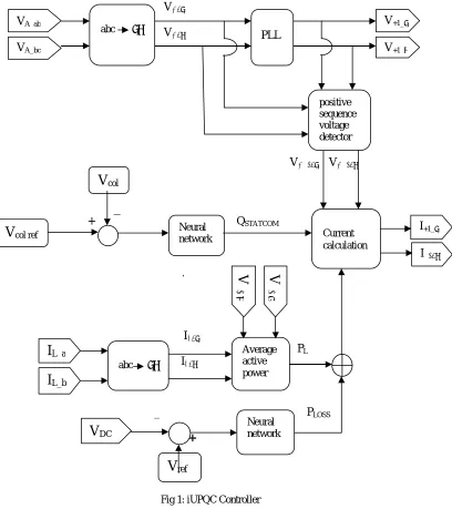
Fig 1: iUPQC Controller
V+1_α PLL V+1_β positive sequence voltage detector
V
col I+1_α Neuralnetwork Current
calculation
I+1_β
V
col refV
+ 1 βV
+ 1 αabc αβ
I
L_a Averageactive power
I
L_b Neural networkV
DCV
ref VA_ab VA_bcOn the other hand, the UPQC between bus A and bus B, can diminish the harmonic currents of the non-linear loads and regulate the voltage at bus B, but it cannot regulate the voltage at bus A. Hence, to accomplish all the required goals, a STATCOM at bus A and a UPQC between bus A and bus B should be applied. The cost of this solution would become high. Fig.1 shows the working iUPQC controller.
An efficient iUPQC controller provides beside all those functionalities of this equipment and also reactive power support to bus A. The modified iUPQC can provide the following functionalities:-
a) It controls the energy and power flow between the grid and the microgrid. b) It provides voltage/frequency support at bus B of the microgrid.
c) It provides reactive power support at bus A of the power system.
d) It provides harmonic voltage and current isolation between bus A and bus B. e) It provides “smart” circuit breaker as an intertie between the grid and the microgrid. f) It provides voltage and current imbalance compensation
The shunt converter provides a controlled, sinusoidal voltage at bus B, which represents the above mentioned functionality (b). Whereas, the series converter of an efficient iUPQC uses only an active power control variable, p, for synthesize a fundamental, sinusoidal current drawn from the bus A, relevant with the active power demanded by bus B. The DC link of the iUPQC has no large energy storage system, the control variable p also attend as an additional active power reference to the series converter to maintain the energy inside the dc link of the iUPQC. Inputs of the controller are voltages at bus A and B, the current demanded by bus B, IL and the voltage VDC of the common dc link. Outputs of the controller are shunt voltage reference and the series current reference. For calculating the grid voltage in αβ -reference frame, the clark transformation is applied to the measured variables. The input of PWM controller is the output of Phase-Locked-Loop (PLL). Since the modified iUPQC can regulate the grid voltage, therefore both the buses will be regulated independently to obtain their reference values. The series converter synthesizes the current drawn from the grid bus. This current can be calculated by adding the average active power required by the loads PL, and the power loss PLoss. The load active power can be calculated by:
PL = V+1 α * iL α + V+1 β * iL β
Where iL α , iL β are the load currents and V+1 α , V+1 β are the voltage references for the shunt converter. The low pass
filter gives average active power (PL). The power loss signal PLoss is determined by using a Neural Network, by comparing the measured dc voltage VDC with its reference value. An additional control loop is employed to regulate the voltage at the grid bus like a STATCOM, which is represented by the control signal QSTATCOM. This control signal is obtained by the Neural Network. The error between the reference value and actual aggregate voltage of the grid bus is applied to the Neural Network.
The performance of iUPQC using PI controller is shown in fig.2, where the circuit breaker closes at 0.25sec. The waveforms of source current, load current, are shown. In the improved unified power quality conditioner (iUPQC) using PI controller, the load current is zero before 0.25 sec. The magnitude of load current is less.
Fig.3 Performance of iUPQC using PI controller, source voltage, load voltage
The performance of iUPQC using PI controller is shown in fig.3, where the circuit breaker closes at 0.25sec. The waveforms of source voltage, load voltage are shown. In the improved unified power quality conditioner (iUPQC) using PI controller, the load voltage is not exactly balanced after 0.25 sec. Which has been improved in iUPQC using Neural Network.
Fig.4 Performance of iUPQC using Neural Network, source current, load current
Fig.5 Performance of iUPQC using Neural Network, source voltage, load voltage
The performance of iUPQC using Neural Network is shown in fig.5, where the circuit breaker closes at 0.25sec. The waveforms of source voltage, load voltage are shown. In the improved unified power quality conditioner (iUPQC) using Neural Network, the load voltage is balanced after 0.25 sec.
Fig.6 Total Harmonic Distortion of iUPQC using PI controller
Fig.7 shows the Total Harmonic Distortion (THD) of the iUPQC using Neural Network. Where the Total Harmonic Distortion of iUPQC using Neural Network is 1.71% at fundamental frequency (50Hz). Hence, the iUPQC using PI controller gives low Total Harmonic Distortion, voltage sag/swell compensation, voltage and current harmonic compensation, power factor compensation and fast dynamic response.
IV. CONCLUSION
An efficient iUPQC controller has been presented and tested in simulation. The structure of the proposed technique allows the compensation of reactive power, voltage and currents harmonics simultaneously and mitigates voltage sag and swell. Overall it improves the quality of power supply and also compensate the Total Harmonic Distortion. It gives fast dynamic response. This technique raise the applicability of the iUPQC and endows new resolutions in future scenarios. It provides grid voltage regulation which reduces the inner loop circulating power inside the iUPQC.
REFERENCES
[1] K. Karanki, G. Geddada, M.K. Mishra, and B.K. Kumar, "A Modified Three-Phase Four-Wire UPQC Topology With Reduced DC-Link Voltage Rating," IEEE Trans. Ind. Electron., vol. 60, no. 9, pp. 3555-3566, Sep. 2013.
[2] V. Khadkikar and A. Chandra, "A New Control Philosophy for a Unified Power Quality Conditioner (UPQC) to Coordinate Load-Reactive Power Demand Between Shunt and Series Inverters," IEEE Trans. Power Del., vol. 23, no. 4, pp. 2522-2534, Oct. 2008.
[3] Kian Hoong Kwan, Ping Lam So, and Yun Chung Chu, "An Output Regulation-Based Unified Power Quality Conditioner With Kalman Filters," IEEE Trans. Ind. Electron., vol. 59, no. 11, pp. 4248-4262, Nov. 2012.
[4] Singh, B., Al-Haddad, K. and Chandra, A. "A review of active filters for power quality improvement". IEEE Transactions on Industrial Electronics, 1999, Vol. 46.
[5] Akagi, H., Watanabe, E. H. and Aredes, M. “Instantaneous Power Theory and Applications to Power Conditioning”. New Jersey : Wiley Inter Science A John Willey & Sons Inc, IEEE Press Series on Power Engineering, 2007.
[6] Kesler, M. and Ozdemir, E. "A novel control method for unified power quality conditioner (UPQC) under non-ideal mains voltage and unbalanced load conditions". Applied Power Electronics Conference and Exposition (APEC), 2010 Twenty-Fifth Annual IEEE.
[7] Khadkikar, V. and Chandra, A. "A Novel Structure for Three- Phase Four-Wire Distribution System Utilizing Unified Power Quality Conditioner (UPQC)". IEEE Transactions on Industry Applications. 2009.
[8] E.W.Gunther and H.Mehta, “A survey of distribution system power quality”,IEEE Trans. On Power Delivery, vol.10, No.1, pp.322-329, Jan.1995.
[9] B.Singh,V. Verma,A. Chandra and K. Al-Haddad, “Hybrid filters for power quality improvement,”Proc. IEE on Generation, Transmission and Distribution, vol.152,pp.365-378,May2005.
[10] J. J. Sanchez-Gasca, N. W. Miller, E.V. Larsen, A. Edris, and D. A. Bradshaw, "Potential benefits of STATCOM application to improve generation station performance," in Transmission and Distribution Conference and Exposition, 2001 IEEE/PES, vol. 2, 2001, pp. 1123--1128 vol.2.
[11] C.A Sepulveda, J.A Munoz, J.R. Espinoza, M.E. Figueroa, and P.E. Melin, "All-on-Chip dq-Frame Based D-STATCOM Control Implementation in a Low-Cost FPGA," IEEE Trans. Ind. Electron., vol.60, no. 2, pp. 659-669, 2013.
[12] B. Singh and S.R. Arya, "Back-Propagation Control Algorithm for Power Quality Improvement Using DSTATCOM," IEEE Trans. Ind. Electron., vol. 61, no. 3, pp. 1204-1212, 2014.
[13] M. Aredes and R.M. Fernandes, "A dual topology of Unified Power Quality Conditioner: The iUPQC," in Power Electronics and Applications, 2009. EPE '09. 13th European Conference on, 2009, pp. 1-10.
[14] M. Aredes and R.M. Fernandes, "A unified power quality conditioner with voltage SAG/SWELL compensation capability," in Power Electronics Conference, 2009. COBEP '09. Brazilian, 2009, pp. 218-224.
[15] B.W. Franca and M. Aredes, "Comparisons between the UPQC and its dual topology (iUPQC) in dynamic response and steady-state," in IECON 2011 - 37th Annual Conference on IEEE Industrial Electronics Society,2011, pp. 1232-1237.
[16] B.W. Franca, L.G.B. Rolim, and M. Aredes, "Frequency switching analysis of an iUPQC with hardware-in-the-loop development tool," in Power Electronics and Applications (EPE 2011), Proceedings of the 2011-14th European Conference on, 2011, pp. 1-6.
[17] R.J. Millnitz dos Santos, M. Mezaroba, and J.C. da Cunha, "A dual unified power quality conditioner using a simplified control technique," in Power Electronics Conference (COBEP), 2011 Brazilian, 2011, pp. 486-493.
[18] Yi Tang et al., "Generalized Design of High Performance Shunt Active Power Filter With Output LCL Filter," IEEE Trans. Ind. Electron., vol. 59, no. 3, pp. 1443-1452, Mar. 2012.
[19] J.M. Guerrero, Poh Chiang Loh, Tzung-Lin Lee, and M. Chandorkar, "Advanced Control Architectures for Intelligent Microgrids-Part II: Power Quality, Energy Storage, and AC/DC Microgrids," IEEE Trans. Ind. Electron., vol. 60, no. 4, pp. 1263-1270, Apr. 2013.
[20] S.R. Bowes and S. Grewal, "Novel harmonic elimination PWM control strategies for three-phase PWM inverters using space vector techniques,"IEE Proc Electr Power Appl, vol. 146, no. 5, pp. 495-514, 1999.
[21] M. Aredes, K. Heumann, and E. H. Walandble, “An universal active power line conditioner,” IEEE Trans. Power Del., vol. 13, no. 2, pp. 545– 551, Apr. 1998.
[22] Arindam Ghosh, Gerard Ledwich,“ Power Quality Enhancement Using Custom Power Devices” Kulwer International Series in Engineering and Computer Science, 2002.