Western University Western University
Scholarship@Western
Scholarship@Western
Electronic Thesis and Dissertation Repository
12-10-2012 12:00 AM
Experimental Investigation of the Fluid Temperature Field and the
Experimental Investigation of the Fluid Temperature Field and the
Thermal Performance of Insert Devices in a Flat-Plate Solar
Thermal Performance of Insert Devices in a Flat-Plate Solar
Collector
Collector
Gurveer Singh Sandhu
The University of Western Ontario Supervisor
Dr. Kamran Siddiqui
The University of Western Ontario
Graduate Program in Mechanical and Materials Engineering
A thesis submitted in partial fulfillment of the requirements for the degree in Master of Engineering Science
© Gurveer Singh Sandhu 2012
Follow this and additional works at: https://ir.lib.uwo.ca/etd
Part of the Energy Systems Commons, and the Heat Transfer, Combustion Commons
Recommended Citation Recommended Citation
Sandhu, Gurveer Singh, "Experimental Investigation of the Fluid Temperature Field and the Thermal Performance of Insert Devices in a Flat-Plate Solar Collector" (2012). Electronic Thesis and Dissertation Repository. 1007.
https://ir.lib.uwo.ca/etd/1007
This Dissertation/Thesis is brought to you for free and open access by Scholarship@Western. It has been accepted for inclusion in Electronic Thesis and Dissertation Repository by an authorized administrator of
EXPERIMENTAL INVESTIGATION OF THE FLUID TEMPERATURE FIELD AND THE THERMAL PERFORMANCE OF INSERT DEVICES IN A FLAT-PLATE SOLAR
COLLECTOR
(Spine title: Experimental study of temperature field in flat-plate collector and heat transfer enhancement with the use of insert devices)
(Thesis format: Integrated Article)
by Gurveer Sandhu
Graduate Program in Engineering Science, Department of Mechanical and Materials Engineering
A thesis submitted in partial fulfillment of the requirements for the degree of
Master of Engineering Science
The School of Graduate and Postdoctoral Studies The University of Western Ontario
ii
THE UNIVERSITY OF WESTERN ONTARIO
School of Graduate and Postdoctoral Studies
CERTIFICATE OF EXAMINATION
Supervisor
______________________________ Dr. Kamran Siddiqui
Supervisory Committee
______________________________ Dr. Jerzy M. Floryan
______________________________
Examiners
______________________________ Dr. Anthony G. Straatman
_____________________________ Dr. Madhumita B. Ray
______________________________ Dr. Roger E. Khayat
______________________________
The thesis by
Gurveer Sandhu
entitled:
Experimental investigation of the fluid temperature field and the thermal
performance of insert devices in a flat-plate solar collector
is accepted in partial fulfillment of the requirements for the degree of Master of Engineering Science
iii
Abstract
An experimental study on the thermal flow behavior inside a flat-plate collector and the impact of insert devices (passive heat transfer enhancement techniques) on the thermal performance of the collector is presented. Temperature fields were obtained for different Reynolds numbers (250-650) and at different inclination angles of the collector. The results show that a stratified flow is developed inside the collector and the warmer fluid restricts itself to the upper portion of the collector only. Various new configurations of the conventional insert devices were tested over a wide range of Reynolds number (200-8000). Comparison of these devices show that in laminar flow regime, wire mesh proves to be an effective insert device and enhances Nusselt number by 270% while in turbulent flow regime while in Reynolds number range 2700-8000, concentric coil insert significantly increases the heat transfer and an increase of 460% in Nusselt number is witnessed.
Keywords
iv
Co-Authorship Statement
I hereby declare co-authorship in the following chapters:
Chapter 2 is the journal article submitted to the Solar Energy and is in review. The complete reference is G. Sandhu, K. Siddiqui, and A. Pinar, Experimental study on the combined effects of inclination angle and insert devices on the performance of a flat-plate solar collector, Solar Energy (2012).
v
Acknowledgements
vi
Table of Contents
Certificate of Examination ... .ii
Abstract ... iii
Co-Authorship Statement ... iv
Acknowledgments ... v
Table of Contents ... vi
List of Figures ... x
Chapter 1: Introduction ………1
1.1 Introduction ... 1
1.2 Literature Review ... 3
1.3 Motivation ... 9
1.4 Objectives ... 10
1.5 Methodology ... 11
1.6 Thesis Layout ... 11
1.7 References ... 11
Nomenclature for Chapter 2 ... 15
Nomenclature for Chapter 3 ... 16
vii
Chapter 2: : Investigation of the fluid temperature field inside flat-plate collector tube
…….………...17
2.1 Abstract. ... ...17
2.2 Introduction ... 18
2.3 Experimental Setup ... 21
2.3.1 Solar Collector………..……….21
2.3.2 Thermocouple rake assembly………….………22
2.3.3 Panel Heater……….………..…22
2.3.4 The support frame……….………23
2.3.5 Temperature sensors………....……..…………...………23
2.3.6 Measurement locations inside and on the collector…….….………23
2.3.7 Calibration……….………...………24
2.3.8 Insulation……….……….24
2.3.9 Data Acquisition………...……….24
2.3.10 Experimental conditions and procedure……….……….24
2.4 Data reduction ... 25
2.5 Results... 26
2.6 Conclusion ... 36
2.7 References ... 37
viii
2.9 Figures ... 41
Chapter 3:Experimental study on the combined effects of inclination angle and insert devices on the performance of a flat-plate solar collector……….………60
3.1 Abstract ... 60
3.2 Introduction ... 60
3.3 Experimental Setup ... 64
3.3.1 Solar Collector……….……….……..…..……….65
3.3.2 Panel heater and PID controller…….….………….………65
3.3.3 The support frame………..……..………66
3.3.4 Temperature sensors…….……….………66
3.3.5 Positions of thermocouples on the solar collector……….………67
3.3.6 Insulation……….………….…….………67
3.3.7 Data Acquisition System and Labview…….…….……….………67
3.3.8 Inserts……...…………...……….…...……..………68
3.3.8.1 Twisted tapes………..………68
3.3.8.2 Coils………68
3.3.8.3 Wire mesh……….………69
3.3.9 Experimental conditions and procedure………..………69
3.3.10 Calibration of Thermocouples……….………70
ix
3.5 Results and Discussion ... 72
3.5.1 Comparison of smooth tube results for three inclination angles……… 73
3.5.2 Performance of various coil inserts at different inclinations…….….……… 77
3.5.3 Comparison of coil inserts ………....………. 78
3.5.4 Performance of twisted tapes at different inclinations …….………..… 79
3.5.5 Comparison of twisted tape inserts ……… 80
3.5.6 Mesh performance evaluation at three inclination angles …….…...……… 81
3.5.7 Comparison of the best insert among coil and twisted tape families with the and the smooth tube……… 82
3.6 Conclusion……….……….84
3.7 References……….………..…………...85
3.8 Figures ……….…………..……….……...………...89
Chapter 4: Conclusion……….112
4.1 Conclusion ... 112
4.2 Significance of findings ... 113
4.3 Future recommendations ... 114
x
List of Figures
2-1: Experimental setup and water circuit layout………...41
2-2: The rake assembly..………...………...………...42
2-3: Locations of thermocouples relative to the collector tube…….………...….43
2-4: The supporting frame for the collector and the heater………...44
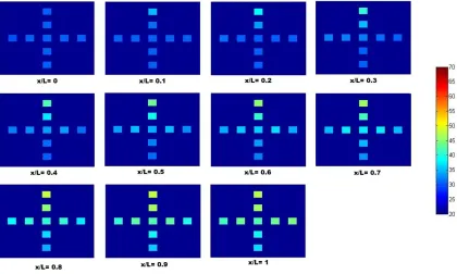
2-5: Temperature Temperature colormaps at various cross-sections along the collector length at the lowest Reynolds number (250), Tp = 250˚C and θ= 0˚. The colorbar is in oC.………...45
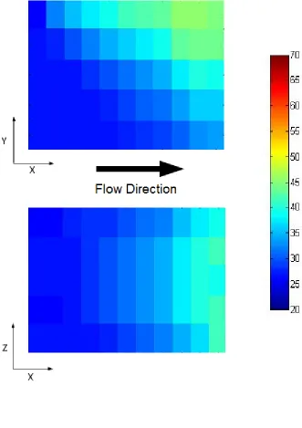
2-6: Temperature colormaps inside the collector in vertical(x-y) and horizontal(x-z) planes at the lowest Reynolds number (Re=250), Tp = 250˚C and θ= 0˚. Colorbar indicates temperature in oC.………..………..……....46
2-7: Temperature colormaps at various cross-sections along the collector length at the highest Reynolds number (Re=620), Tp = 250˚C and θ= 0˚. Colorbar indicates temperature in oC.……….………..…..….47
2-8: Temperature colormaps inside the collector in vertical (x-y) and horizontal(x-z) planes at the highest Reynolds number (Re =620), Tp = 250˚C and θ= 0˚. Colorbar indicates temperature in oC………..……….………....…..48
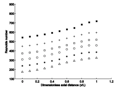
2-9: Variation of the local Reynolds number along the collector length at average Reynolds Re=620 =250˚C and θ= 0˚………..…49
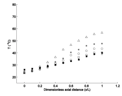
2-10: Local fluid temperatures versus dimensionless axial distance(x/L) at different Reynolds Tp =250˚C and θ= 0 ˚……….…………50
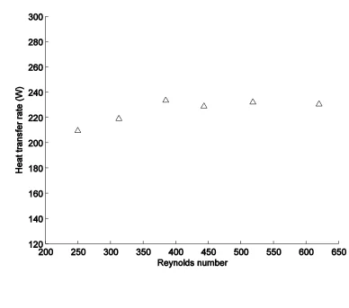
2-11: Heat Heat transfer rate versus Reynolds number for Tp = 250˚C and θ= 0˚………51
2-12: Local Reyleigh number versus dimensionless axial distance (x/L) at different Reynolds ………..52
xi
different panel heater temperatures; Tp= 250˚C, 275˚C and 300˚C at Re= 250 and
θ=0˚……….….54
2-15: Variation of the local fluid temperature along the collector length at different heater ˚……...55
2-16: Colormaps of the temperature field in the vertical (x-y) and horizontal (x-z) planes inside the collector at three different inclinations of the collector: θ= 0˚, 30˚ and 45˚ at Tp= 250˚C and Re= 250………56
2-17: Colormaps of the temperature field in the vertical (x-y) and horizontal (x-z) planes inside the collector at three different inclinations of the collector: θ= 0˚, 30˚ and 45˚ at Tp= 250˚C and Re= 620 ………..……….…………....57
2-18: Local Variation of the local fluid temperature along the collector length at three inclination angles = 250˚C and Re= 250……..…58
2-19:Variation of the local fluid temperature along the collector length at three inclination angles 620……….59
3-1: Experimental setup and water circuit layout……….…...…89
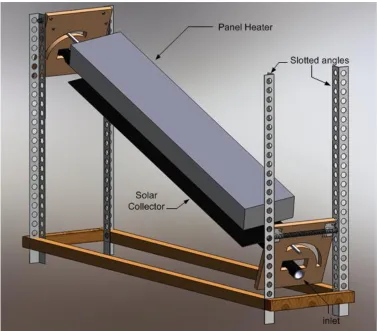
3-2: 3-D model of the support frame………...…….…...90
3-3: Locations of thermocouples on the flat plate collector………....91
3-4: Twisted tape inserts geometry………..92
3-5: Coil insert (C-1) …..……….………93
3-6: Coil away from the tube wall(C-2)………...………..……….….... 94
3-7: Concentric coils (C-3)………...………....95
3-8: Conical coil (C-4)……….96
3-9: Mesh insert………...97
3-10: Nusselt number variations for the collector without any insert (base case) for three collector inclinations: horizontal (O); 30˚() and 45˚() at various flow rates (200<Re<8000). The Nusselt number estimated from the correlation provided by Churchill and Ozoe [21] (—); and Gnielinski [22] (- - -) are also plotted for comparison…………98
xii
collector inclinations: horizontal (O); 30˚() and 45˚() at various flow rates
(200<Re<8000)………100 3-13: Nusslet number variation for 3 collector inclinations: horizontal (O); 30˚() and 45˚() at
various flow rates (200<Re<8000) for coil family inserts. (a) Coil insert (C- 1), (b) Coil(C- 2) away from the tube wall (c) Concentric coils (C-3) (d) Conical coils(C-4)………….101 3-14: Nusselt number variations for coil family inserts: Coil(O); Coil away from the tube
wall(+); Concentric coils(); Conical coils() and comparison with smooth tube(); at various flow rates and at horizontal orientation of the collector………...……… 105 3-15: Nusslet number variation for 3 collector inclinations: horizontal (O); 30˚() and
1
Chapter 1
Introduction
1.1Introduction
It is anticipated that from 2010 to 2030, world primary energy demand will increase at a rate of 1.7 % per annum [1]. Despite the harmful emissions from the burning of fossil fuels, the reliance of fossil fuels to meet the global energy demand will continue over the next few decades. It has been predicted that 75% of the global energy demand would still be fulfilled by fossil fuels in 2035 [2]. This continued consumption of fossil fuels will have detrimental effects on the environment and may lead to some catastrophic outcome. According to the International Energy Agency, if no strict actions are taken by 2017 then all existing energy infrastructure would surpass the allowable carbon emission limit and hence there will be no room for additional power plants, factories and other infrastructure, except for those with zero-carbon emissions [2]. Despite the issue of harmful emissions, another major concern with fossil fuels is their shrinking reserves. It has been predicted that world petroleum reserves will last for almost 100 years, while the natural gas reserves are expected to last for over 150 years [3].
2
pace of advancement is slow. It has been predicted that the share of non-hydro renewables in the power generation will increase to 15% in 2035 from 3% share in 2009 [2].
In cold climate like Canada, a major fraction of the energy consumption in the residential sector is for space and water heating. According to statistics, in the Canadian residential sector, 63% of the total energy is used for space heating, while 18% is utilized for water heating [4]. In the commercial and institutional sectors, the heating fraction reduces to about 50% [4]. Electricity is the major source of energy for water heating in Canada and constitutes about 50% of the total water heating demand, while, 43% of water heating relies on natural gas, and remaining 7% utilize other sources such as oil [5]. Therefore, the need for renewable technologies is not only for power but also for heating.
3
external fins are often attached as absorber plates and are painted black to increase their thermal absorptivity. The bottom surface is kept insulated and the entire collector assembly is placed inside a glazed surface which keeps the heat trapped to increase its efficiency [7]. The thermal energy absorbed by the absorber plates is conducted to the tube which further increases the heat transfer to the working fluid flowing through the collector tube. The payback period for solar water heaters is much shorter than PV solar but cost is still not competitive against the conventional water heating systems. Therefore, efforts are needed to reduce the system cost and/or increase the system efficiency.
1.2 Literature Review
Many researchers in the past have analysed the hydro-dynamic and thermal behavior inside the circular tubes and flat-plate collectors. A general observation in this concern is that a stratified flow is developed in the collector. The warmer fluid rises as a result of buoyancy produced and remains in the upper portion of the collector whereas the colder fluid being heavier, remains in the lower part. In a flat plate solar collector, direct radiation from the sun is incident only on the upper face of the collector, which leads to a non-uniform temperature distribution around the collector tube. Heat transferred to the tube by fins via fin-tube joints further complicates the thermal behavior. These factors lead to the development of stably stratified flow in the upper part of the tube, whereas in the lower part, an unstably stratified flow is developed due to the heat conducted circumferentially to the lower surface of the tube [8].
4
5
secondary flow which forces the warmer fluid to stay in the upper section and the colder fluid near the bottom.
6
7
case of externally finned tubes, five times more energy is transferred to the fluid as compared to a simple tube. They argued that this energy gain is not constant throughout the collector length but observed a linear decrease along the tube axis. They also noticed that fluid extracts more energy from the bottom portion of the collector as compared to upper portion. They observed that far downstream, when flow becomes thermally fully developed, the isotherms at any given cross section become distorted due to secondary flow development.
There are generally three kinds of heat transfer enhancement techniques: Active, Passive and Compound techniques [20]. The prime objective of these techniques is to increase turbulence which increases mixing and hence enhances the heat transfer. Active heat transfer enhancement techniques require an external power source to increase turbulence, e.g. vibrations, surface rotation, jet impingement etc. Passive techniques involve modification of the surfaces (addition of fins or corrugated surfaces) or use of insert devices such as twisted tapes, wire coils etc to generate turbulence. When a combination of two or more of the above mentioned techniques is used simultaneously, it is called compound technique for heat transfer enhancement.
Several studies have been reported in the literature that investigated various passive heat transfer augmentation techniques. These investigations were made in standard circular tubes as well as in solar collectors.
8
9
with Re<200, no device was able to enhance heat transfer because of the dominance of natural convection. Garcia et al. [26] investigated the performance of wire coil inserts as a heat transfer augmenting device in circular tubes and found that wire coil inserts performed the best in the transitional flow regime. They also noticed that wire coil inserts contribute to the transition from laminar to turbulent flow. Sarada et al. [27] numerically studied heat transfer augmentation by using mesh inserts inside a circular tube. They used air as fluid inside the tube and covered a Reynolds range from 7000 to 14000. They observed that an increase in Reynolds number and ratio of porous material led to an increase in the Nusselt number. They argued that with the mesh insert, mixing of the fluid occurs rapidly due to increased obstruction. Durmus et al. [28] tested a heat exchanger with a snail entrance. They experimented with a concentric heat exchanger with air in the inner tube while hot water in the annulus. The purpose of the snail was to create a swirl in the flow so as to improve mixing and therefore increase the heat transfer. They found that the Nusselt number was increased significantly with the use of swirl generator or snail entrance. They also observed that heat transfer increased with an increase in the swirling angle and heat transfer augmentation was as high as 160-185% with the highest swirling angle of 750.
1.3 Motivation
10
heaters. However, one key aspect which still lacks fundamental understanding the thermo-fluid processes inside the collector tube, which is the heart of the system where the actual transfer to the working fluid takes place. Very limited work has been conducted to investigate the thermo-fluid process inside the collector tube. To the best of our knowledge, the only notable work conducted in this area was an experimental study by Sookdeo and Siddiqui [8], who measured the velocity field inside the collector tube and the numerical study of Ouzzane & Galanis[19] who studied the flow in inclined tubes with fins. The better understanding of the thermo-fluid process inside the collector tube is vital to develop effective ways to enhance heat transfer. Several studies have reported the enhancement of heat transfer using insert devices in the tube. These studies mostly considered one type of the insert device and studied its performance. There is a need for a comprehensive and systematic investigation of different types of inserts to indentify the best insert types. Furthermore, in the previous studies, the impact of insert was tested only for the horizontal tubes. As the solar collectors are installed with the tilt angle equal to the local latitude, it is important to investigate the performance of these inserts in the tilted collectors.
1.4 Objectives
The objectives of the present research is,
1. To investigate the temperature field inside the flat-plate collector tube
11 1.5 Methodology
The above objectives are met through an experimental study conducted in a laboratory environment using a real flat-plate solar collector. The experiments were conducted over a range of Reynolds number from 200 to 8000, for three tilt angles of the collector: 0˚, 30˚ and 45˚ at three different incident radiant heat flux conditions. Various insert device configurations were tested including some novel configurations.
1.6 Thesis layout
The layout of the thesis as follows: Chapter 1 is the introduction discussing the background and the motivation for the present research. Chapter 2 presents the detailed investigation of the temperature field inside the collector tube. Chapter 3 deals with the comprehensive investigation of the performance of various insert devices in the flat-plate collector tube. The main results are concluded in Chapter 4 along with some future recommendations.
1.7 References
1. BP 2012. BP Statistical review of world energy June 2012.
2. International Energy Agency. 2011. World Energy Outlook 2011. International Energy Agency
12
4. Natural Resources Canada 2009. Energy Efficiency trends in Canada 1990 to 2007. 5. Natural Resources Canada 2007. Survey of household energy 2007
6. Berman, A., Karn, R.K., and Eipstein, M.2006. A new Catalyst System for High Temperature Solar Reforming of Methane. Energy Fuels 20(2). 455-462.
7. Ghosh, G.K. 2010. Solar Energy The Infinite Source, APH Pub. Corp. New Delhi.
8. Sookdeo, S., K, Siddiqui. 2010. Investigation of the flow inside flat-plate collector tube using PIV technique. Solar Energy (84). 917-927.
9. Fan, J., Furbo, S. 2008. Buoyancy Effects on Thermal Behaviour of a Flat-Plate Solar Collector.
10.Fan, J., Shah, L.J., and Fubro, S.2007. Flow distribution in a solar collector panel with horizontally inclined absorber strips. Solar Energy (81). 1501-1511.
11.Alvarez, A., Shah, O., Muniz, M.C., and Varela, L.M.2010. Experimental and numerical investigation of a flat-plate solar collector. Energy (35). 3707-3716.
12.Taherian, H., and Yazdanshenas, E. 2006. Experimental investigation of forced-convection in a finned rhombic tube of flat-plate solar collectors. Proceedings of the Second International Green Energy Conference. IGEC2-126.
13.Mohammed, H.A., and Salman, Y.K.2007. Free and forced convection heat transfer in the thermal entry region for laminar flow inside a circular cylinder horizontally oriented. Energy Conversion and Management (48). 2185-2195.
13
15.Iqbal, M., Stachiewicz, J.W., 1966. Influence of tube orientation on combined free and forced laminar convection heat transfer, ASME J. Heat Transfer 88(1), 109-116.
16.Barozzi, G.S., Zanchini, E., and Mariotti, M.1985. Experimental Investigation of Combined Forced and Free Convection in Horizontal and Inclined Tubes. (20). 18-27. 17.Mare, T., Galanis, N., Voicu, I., Miriel,J. 2006. Experimental analysis of mixed
convection in inclined tubes. Applied Thermal Engineering 26. 1677-1683.
18.Orfi, J., galanis, N. 1999. Bifurcation in steady laminar mixed convection flow in uniformly heated inclined tubes. International Journal of Numerical Methods for Heat and Fluid Flow 9. 543-567.
19.Ouzzane, M., and Galanis, N.2001. Numerical Analysis of Mixed Convection in Inclined Tubes with External Longitudinal Fins. Solar Energy (71). 199-211.
20.Webb, R.L, 1994. Principles of Enhanced Heat Transfer, second ed. Wiley Interscience, New York.
21.Hobbi, A., and Siddiqui, K. 2009. Experimental study on the effect of heat transfer enhancement devices in flat-plate collectors. International Journal of Heat and Mass Transfer (52). 4650-4658.
22.Martin, R.H., Pinar, A.G., and Garcia, J.P.2011. Experimental heat transfer in enhanced flat-plate solar collector. 8-13.
14
24.Gunes, S., Ozceyhan, V., and Buyukalaca, O. 2010. The experimental investigation of heat transfer and pressure drop in a tube with coiled wire inserts placed separately from the tube wall. Applied Thermal Engineering (30). 1719-1725.
25.Garcia, A., Solano, J.P., Vicente, P.G., and Viedma, A.2007. Enhancement of laminar and transitional flow heat transfer in tubes by means of wire coil inserts. International Journal of Heat and Mass Transfer (50). 3176-3189.
26.Garcia, A., Vicente, P.G., Viedma, A. 2005. Experimental study of heat transfer enhancement with wire coil inserts in laminar-transition-turbulent regimes at different Prandtl numbers. International Journal of Heat Mass Transfer 48, 4640–4651.
27.Sarada, S.N., Raju, A.V.S.R., and Radha, K.K.2010. Experimental Numerical Analysis Enhancement of Heat Transfer in a Horizontal Circular Tube using Mesh Inserts in Turbulent Region. ARPN Journal of Engineering and Applied Sciences 4 (5), 53-60. 28.Durmus, A., Durmus, A., and Esen, M.2002. Investigation of heat transfer and pressure
drop in a concentric heat exchanger with snail entrance. Applied Thermal Engineering (22). 321-332.
15 Nomenclature (Chapter-2)
Ac curved surface area of collector tube (m2)
Aₓ cross sectional area of the collector tube (m2
) Cp specific heat of working fluid (J/kgK)
D inner diameter of the collector tube (m) F volumetric flow rate (m3/s)
g acceleration due to gravity (m2/s) Gr Grashof Number
ṁ mass flow rate (kg/s)
kf fluid thermal conductivity (W/mk)
L total length of the heat absorbing area (m) Nu Local Nusselt number
Pr Prandtl number
Ra LocalRayleigh number Re Local Reynolds number q" wall heat flux (W/m2) heat transfer rate (J/s) V axial fluid velocity (m/s) Tp Panel heater temperature
Tf Local mean fluid temperature
Tf(th) Theoretical local fluid temperature for a round tube with uniform heat flux
Tw Local mean wall temperature
x A variable vector along the tube axis lying within the absorbing region and starting from the inlet towards the outlet
μ dynamic viscosity (kg/ms) ρ density of fluid (kg/m3
)
θ angle of inclination of the collector (˚)
Subscripts
1 1st position (cross section of the tube at x= L/2) 2 2nd position (cross section of the tube at x= 3L/4) f bulk fluid
16 Nomenclature (Chapter-3)
Ac surface area of collector tube (m2)
Cp specific heat of working fluid (J/kgK)
C-1 Simple coil (touching the tube wall) C-2 Coil away from the tube wall
C-3 Concentric coils type insert C-4 Conical coil insert
D inner diameter of the collector tube (m)
f Dimensionless friction factor g acceleration due to gravity (m2/s) Gr Grashof number
Gz Graetz number
h twist pitch of a twisted tape k thermal conductivity (W/mk) L total length of the collector (m)
mass flow rate (kg/s) Nu Nusselt number
Num modified Nusselt number
NuG Gnielinski Nusselt number for turbulent flow in a pipe
NuCO Churchill and Ozoe Nusselt number for laminar flow in a pipe
p pitch of the coils (m) Pr Prandtl number
q" wall heat flux (W/m2)
heat transfer rate (J/s) Ra Rayleigh number Re Reynolds number Ri Richardson number T temperature (˚C)
TT1 twisted tape with shortest pitch TT2 twisted tape with medium pitch TT3 twisted tape with longest pitch
x length of the collector measured from inlet (m) Y pitch ratio of the twisted tape
β volumetric thermal expansion coefficient (k-1
) μ dynamic viscosity (kg/ms)
ν kinematic viscosity (m2
/s) ρ density of fluid (kg/m3
)
θ angle of inclination of the collector (˚)
Subscripts
17
Chapter 2
Investigation of the fluid temperature field inside flat-plate collector
tube
2.1 Abstract
18
devices. That is, the insert devices disrupt the stably stratified layer and induce mixing which enhances the heat transfer.
Key words: Flat-plate solar collector; collector fluid temperature fields; stratified flow; local flow properties; inclined collector.
2.2 Introduction
Due to the rising cost of fossil fuels and their detrimental effects on the environment, there is a growing demand to utilize clean renewable energy sources. Among renewable energies, solar energy has the highest potential to meet the growing energy demand. Solar energy can be collected and converted into other forms of energy such as thermal energy, electricity, and chemical energy. The only solar thermal conversion technology that is relatively mature and commercially implemented is the solar water heating systems. In such systems, the collected solar energy is converted into thermal energy which is then used to heat utility water for domestic and light commercial applications. Collector is the core component of any solar water heating system, where the solar thermal energy is transferred to the working fluid. One of the most common types of collectors in use these days is the flat plate solar collector in which two fins are attached to the fluid-carrying tube to collect heat and transfer it to the tube. A flat plate collector uses direct as well as diffuse solar energy. Furthermore, these collectors are relatively low cost and require little maintenance.
19
knowledge of the flow and temperature fields inside the collector tube is vital to improve our understanding of the process of heat transfer from the collector tube to the working fluid.
In flat-plate solar collectors, the flow rates are kept very low to maximize the temperature rise of the working fluid. Hence, the mode of heat transfer to the working fluid is mixed convection where both the forced convection (shear-driven) and free convection (buoyancy-driven) modes are present. Furthermore, the collector tube is exposed to non-uniform heating, i.e. the incident radiant heat flux at the upper surface and temperature hot spots at the joints of the collector plates on each side of the tube. This non-uniform thermal boundary condition significantly alters the velocity field inside the collector tube.
Sookdeo and Siddiqui [1] studied the velocity field inside a flat plate collector tube using particle image velocimetry (PIV) technique at different incident radiant heat fluxes over a range of Reynolds numbers. They observed an asymmetry in the mean velocity profiles due to the non-uniform heating on the tube wall. They argued that the heat transfer due to the direct incident radiant heat flux on the upper tube wall induces stably stratified fluid layer in the upper section of the tube while, the circumferentially conducted heat through the tube wall to the bottom forms the unstably stratified fluid layer in the lower section of the collector tube. They further argued that the amount of heat transfer to the working fluid in the stably stratified layer is lower than that in the unstably stratified layer.
20
and numerical results. They found that at small flow rates, buoyancy effects become prominent due to dominant natural convection which force the fluid to rise along the circumference of the tube and hence the warmer fluid is restricted to the upper part of the collector tube while the colder fluid settles in the lower part.
Fan et al. [4] experimentally and numerically studied the flow distribution in a flat-plate solar collector panel at different flow rates and tilt angles of the collector and observed that the buoyancy effects becomes stronger with a decrease in the flow rate. They also argued that the angle of inclination affects the flow distribution greatly at lower flow rates but not at higher flow rates.
21
As the above literature review shows, very limited work has been conducted on the investigation of the thermo-fluid process inside the flat-plate collector tube. Although Sookdeo and Siddiqui [1] have reported detailed measurements of the mean velocity field inside the collector tube, to the best of authors’ knowledge, no study has reported the detailed investigation of the fluid temperature field inside the flat-plate collector tube and the parameters that influences it. The knowledge of this temperature field is vital to understand the fundamental heat transfer process inside the collector tube, which is necessary in order to develop effective ways to improve the collector heat transfer rate.
The present study is focused on conducting a detailed experimental investigation of the temperature field inside the collector tube. The specific focus is on studying the influence of flow rate, incident heat flux and collector inclination angle on the local temperature fields as well as the thermal development of the flow in the collector tube.
2.3 Experimental setup
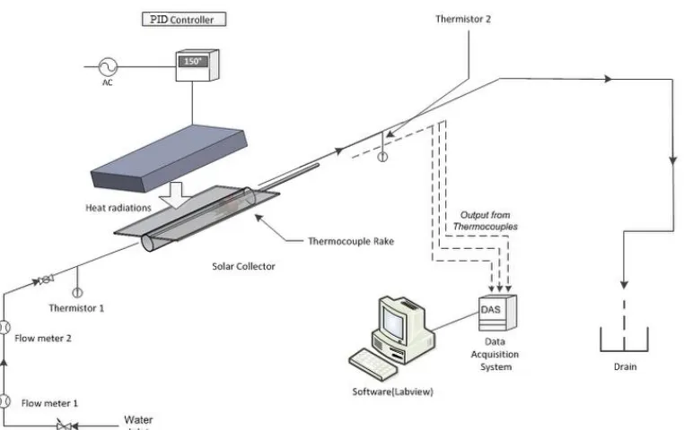
The experiments were conducted in a laboratory environment using water as the working fluid. The experimental setup is shown in Fig. 1. The description of the main system components is provided below:
22
diameters of the tube were 16 mm and 13.38 mm, respectively. Thurmalox solar coating was used to increase the absorptivity of the collector.
2.3.2 The thermocouple rake assembly: The fluid temperature inside the tube was measured at nine locations in a cross-sectional plane using a rake of thermocouples. The complete rake assembly is shown in Fig. 2. It comprised of two rakes made by carefully bending stainless steel wire and attaching legs made of the same stainless steel wire. One rake has four legs and the other has five legs (see Fig. 2). All pieces were attached using epoxy adhesive maintaining an equal distance of 3.3 mm between the legs. The configuration of the rake with respect to the tube diameter is shown in Fig. 3. The rake was attached to the inner side of a thin cylinder whose outer diameter was slightly smaller than the inner diameter of the collector tube so that it could easily slide inside the collector tube. The other end of the cylinder was attached to a long thin steel tube using two metallic legs (see Fig. 2). The outer diameter of this tube was about 4.8 mm and its thickness was 0.5 mm. Nine thermocouples were passed through the tube from the free end and were taken out at the other end and attached to the legs of the rake. The thermocouples were bent carefully so that their tips became collinear with the respective leg of the rake.
23
2.3.4 The support frame: A wooden frame was build to support the collector and the heater (see Fig. 4). The function of the frame was to hold the heater and the collector at various inclination angles. It had the provision for adjusting the inclination angle with the help of two hinge joints. The system could be locked after selecting a particular angle. The structure was designed in such a way that at any given inclination, the collector and the heater remained parallel and separated by a distance of 25 mm.
2.3.5 Temperature sensors: The thermocouples used in the rake were K-type thermocouples: Omega 5TC-GG-K-36-72. Two thermistors (TJ 72–44033) with an accuracy of ±0.1˚C were also used to measure the bulk water temperatures at the inlet and outlet of the collector due to their better sensitivity. The accuracy of the thermocouples was ±0.4 oC and the response time in still air was 1 sec (for 63.2% of the change).
24
some experimental difficulties, the surface temperatures were measured only for the horizontal orientation of the collector.
2.3.7 Calibration: All thermocouples were calibrated by placing them in an insulated hot water bath along with a high accuracy thermometer (Kessler-2150, 76 mm immersion, range -36 to 54oC) which was used as the reference. The water in the bath was allowed to cool down and data was recorded at different bath temperatures. Calibration equations were obtained for all the thermocouples and
were incorporated in the LabView program to obtain corrected temperature data. All the calibration curves provided almost linear relationships with very small bias errors.
2.3.8 Insulation: Reflectix R-4 and glass wool insulations were used to insulate the collector and heater to minimize heat loss to the surrounding. The insulation has three layers i.e. the layer of glass wool was sandwiched between two layers of Reflectix. The three-layered insulation was wrapped around the collector and the heater. The system was insulated from all the sides including inlet and outlet. Pipe insulation was used to insulate pipe fittings at the ends of the collector.
2.3.9 Data Acquisition System and Labview: A National Instruments data acquisition system (SCXI-1000) was used for acquiring data from the sensors. It has a data acquisition card (PCI-6036E), a signal conditioner (SCXI-1102) and a terminal block (SXCI-1303). The data was acquired via LabView software.
25
high range rotameter (Omega FL 4205 controlled with an external valve) and then through low range rotameter (Omega FL-1448-G). The purpose of using the high range flow meter was to minimize pressure fluctuations at the low range flow meter to improve its accuracy.
The experimental procedure is described as follows: The flow rate was set first and then the heater was turned on and the PID controller was set at the desired temperature. The system was allowed to reach a steady state. The data acquisition system was turned on and the temperature measurements were begun when the rake was at position 1 (see Fig. 3). The angular position of the rake was also corrected using the reference scale to ensure that the thermocouples in the rake are positioned horizontally and vertically. Measurements were made at 11 axial locations along the collector tube length (see Fig. 3), by moving the rake outwards. The flow rate was changed and the procedure was repeated. Experiments were conducted at three collector inclination angles of 0˚, 30˚ and 45˚. At each inclination angle, the experiments were conducted at three heater temperatures of 250˚C, 275˚C and 300˚C. At each inclination angle and heat temperature, data was recorded at six different flow rates, which were 0.027, 0.037, 0.047, 0.056, 0.067 and 0.078 gpm. For reference, the corresponding Reynolds number based on no heating condition ranged from 250 to 620. Thus, 54 experimental runs were conducted at different conditions.
2.4 Data Reduction:
The data obtained from the experiments was processed using Matlab software. The time-averaged values of the temperature were used to calculate various dimensionless parameters such as Nusselt number, Reynolds number, and Rayleigh number. The overall rate of heat transfer was calculated as:
26
where ṁ is the mass flow rate, and Tf,o , Tf,i are the bulk fluid temperatures at the collector outlet
and inlet, respectively.
Dimensionless parameters were computed as [10]:
Grashof number: Gr = gβ(Tw,m – Tf,m)D3/ν2 (2)
Prandtl number: Pr = Cp.μ/k (3)
Rayleigh number: Ra = Gr.Pr (4) Nusselt number was estimated using the following correlation:
Nu= (μw/μf)0.14 q"D/(Tw,m – Tf,m)kf (5)
where, (μw/μf)0.14 is the property ratio used for correcting the varying fluid properties for fluid
being heated or cooled [11].
The local mean temperature at a given axial location was computed by spatially averaging all nine temperature measurements at that location. Similarly, the local mean surface temperature was obtained by averaging the surface temperature data from four thermocouples at that axial location.
2.5 Results
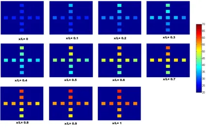
27
increased along the length of the collector tube. The results show that in a given cross-sectional plane, the fluid temperature is not uniform i.e. the highest temperature is observed near the upper end of the tube, while the bottom end of the tube has the lowest temperature. The fluid temperature in the sides lied in between the two extreme values. The highest fluid temperature near the upper end of the tube could be due to the following possible reason. As mentioned in the experimental setup section, the upper end of the tube was attached to the collector plate (see Fig. 3), thus, the heat incident on the collector plate was conducted through the joint to the upper side of the tube. Heat was then transferred to directly to the fluid in the upper section of the tube as well as conducted circumferentially through the tube wall to the lower end. The tube wall temperature measurements show that the wall temperature remained high near the upper end of the tube resulting in the higher fluid temperature in the upper side of the tube. Comparisons of the fluid temperatures near the tube wall with the corresponding wall temperatures show that the wall temperatures are higher than the near-wall fluid temperatures. Although the temperatures are measured at four circumferential locations, which cover the extreme upper and lower ends, the consistent trends at all four locations indicate that the local wall temperatures are higher than the local near-wall fluid temperatures along the entire tube circumference. Thus, the higher wall temperatures in the upper half of the tube maintain the stably stratified flow, while the higher wall temperatures in the lower half of the tube induce convective motions due to unstable stratification.
28
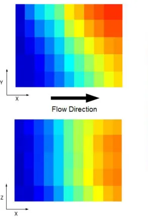
gradually from the top to the bottom of the tube, which indicates that the flow is primarily stably stratified in the cross-sectional planes throughout the collector tube length. The stably stratified fluid layer dampens any convective movement thus, prevents mixing and hence reduces the effective heat transfer within the fluid domain i.e. the heat transfer from the upper fluid layer to the lower fluid layer is primarily due to conduction rather than convective currents. The absence of relatively uniform temperature field in the vertical plane indicates that the convective motions induced by the wall heating in the lower section of the tube were restricted to very thin layer near the lower tube wall section.
The plot also shows that the fluid temperature is not uniform at the exit of the collector. There is almost 10oC temperature difference between the fluid in the upper and lower sections of the tube. As mentioned above, the formation of the stably stratified fluid layer prevents the formation of strong convective currents, which affects the heat transfer. It should be noted that in any practical setup, only the upper surface of collector is exposed to the heat flux and hence, the formation of the stably stratified layer in the collector tube is natural, and hence, the inefficient heat transfer is unavoidable. Therefore, other means such as inserts are used to mechanically induce mixing within the collector tube to enhance heat transfer.
29
rises along the tube length. With an increase in the axial distance, the fluid temperature rise propagates downward in the vertical plane. The temperature data in the horizontal plane shows almost symmetric behavior about the centerline of the tube. Results also show that at a given axial location, the fluid temperatures near the channel centreline are slightly higher than those away from the tube center in particular near the tube exit. The temperature gradients in the vertical plane also vary with the axial distance. That is, the temperature gradients are strongest in the upper section of the tube near the collector inlet, while the temperature gradients are stronger in the lower section of the tube near the collector exit.
Fig. 7 shows the fluid temperature variations in the cross-sectional planes inside the collector at the highest Reynolds number, i.e. 620 at the panel heater temperature (Tp) of 250oC. It is seen
30
The trends observed in Figs. 5-8 are similar indicating that in this Reynolds number range, the trend of the thermal development of the flow is similar however, the temperature magnitude decreases with an increase in the Reynolds number. Similar trends are also observed at all other cases. The results presented in Figs. 5-8 provide a perception of the structure of temperature field inside a flat-plate collector tube at any particular flow rate, incident radiant heat flux and the inclination angle. In the following, the quantitative assessment of the impact of various parameters is presented.
31
increased by about 35%. This indicates that in the flat-plate collector, the viscous effects reduce at a faster rate at lower flow rates.
32
further increase in the Reynolds number by 17% (Re=518), the fluid temperature rise reduced by 17%. That is, as the Reynolds number increases, the effect of increase in the flow rate is compensated by an almost equal reduction in the fluid temperature rise. This effect is evident in the plot of the rate of heat transfer to the water in the collector tube at the same conditions, which is shown in Fig. 11. The figure shows that the heat transfer rate increased with the Reynolds number in the lower range but remained almost unchanged in the range 400 < Re < 550. Similar trends are observed at other conditions.
33
The Rayleigh number quantifies the relative contribution of fluid stratification with respect to the viscous effects. Figs. 5-8 show that the stratification in the tube increases with the distance. Furthermore, the fluid viscosity decreases along the tube due to the increase in the fluid temperature (see Fig. 9). Thus, the increase in the Rayleigh number is contributed by both the increase in the stratification and decrease in the viscosity magnitude with the distance in the collector tube. The sensitivity of the Rayleigh number to the fluid temperature change is high as both stratification and viscosity are dependent on the fluid temperature. As Fig. 10 shows, the fluid temperature changes nonlinearly with the Reynolds number, this effect is further enhanced for the Rayleigh number as evident in Fig. 12.
The variation of the local Nusselt number along the collector length is shown in Fig. 13.The plot shows that the Nusselt number remains fairly constant along the collector length at all the three axial positions. A slight decreasing trend of the Nusselt number is observed in the first half of the collector tube. In the second half, the Nusselt number continued to increase at all the three Reynolds numbers. Previous studies have shown that in conventional laminar channel flows, the Nusselt number decreases along the tube length in the entrance section and then remains almost constant in the developed flow region of the tube [8]. Nusselt number is the ratio of convective to conductive heat transfer. In conventional channels, once the flow is developed, the relative contributions of convective and conductive heat transfer is expected to be the same and hence the constant Nusselt number. In the flat-plate collector tube, the trends are somewhat different from that observed in the conventional laminar channel flows. A plausible explanation of these variations is provided below.
34
flows are typically exposed to uniform thermal boundary conditions, while, in flat-plate collectors, the thermal boundary condition is non-uniform due to the higher heat flux on the upper tube wall as discussed earlier. This induces a stably stratified fluid layer in most of the tube cross-sectional plane, which reduces the convective currents and increases the conduction heat transfer. In the lower section of the tube the convective current are present within the fluid layer near the wall. Therefore, the trend of local Nusselt number variation is highly dependent on the strength of the stably stratified layer and the convective current layer. The results in Fig. 13 show that in the second half of the collector, Nusselt number increases at a lower rate at low Reynolds number compared to that at the high Reynolds number. The earlier results have indicated that the stable stratification effects are strongest at the lowest Reynolds number and hence a higher magnitude of conduction heat transfer. Therefore, the increase in Nusselt number is relatively small at the lower Reynolds number. As the Reynolds number increases, the strength of stratification becomes weaker and hence the magnitude of conduction heat transfer decreases. This results in an increase in the Nusselt number. Mohammed and Salman [5] also observed an increase in the Nusselt number with an increase in Reynolds number in the second half of the tube under constant heat flux condition. It should be noted that these variation are relatively small. Thus, it can be concluded that the Nusselt number trends in flat-plate collector tube are in general similar to that in the conventional laminar channel flows. However, some variations are observed due to the change in the relative strength of the stably stratified layer.
35
the collector for three heater temperatures at the Reynolds number of 250. Overall, the temperature maps show similar trend of the temperature variation in the vertical direction as well as along the collector length. At a given location, the fluid temperature in general, increased with an increase in the incident heat flux, as expected. The corresponding local fluid temperatures averaged at a given cross-section are plotted against the collector length in Fig. 15. As expected, the local fluid temperature increased with an increase in the incident heat flux. The local fluid temperature trends are similar at all incident heat flux conditions. These trends are already discussed in Fig. 9.
36
for this trend is already discussed above. Fig. 18 shows that except for the entrance section, the fluid temperature rise in the inclined collectors is almost linear, whereas, the horizontal collector shows relatively rapid temperature rise in the middle of the collector and minimal temperature rise near the inlet and the exit. Again, the increased mixing in the inclined collectors could be the possible reason for the continuous increase in the fluid temperature. These linear trends are not evident at the highest Reynolds number.
The results in this study provided a better perception of the structure of the fluid temperature field inside the collector. The results show that the local temperature increment along the channel axis is almost linear except near the entrance and exit sections. The results also showed the presence of stably stratified layer in the collector and the strength of stratification increased with a decrease in the Reynolds number. Several studies have reported the heat transfer enhancement by using insert devices in the collector tube. The present study provides the physical explanation for this enhancement. That is, the stably stratified layer suppresses the convective currents and hence mixing and, the insert devices disrupt this layer and induce mixing which enhances the heat transfer.
2.6Conclusion
37
temperature data in the horizontal plane shows almost symmetric behavior about the centerline of the tube. The temperature gradients in the vertical plane also vary with the axial distance. That is, strong temperature gradients in the upper section of the tube near the collector inlet and in the lower section of the tube near the collector exit. Results also show that the local-average fluid temperature increased nonlinearly over the collector length and its magnitude decreased with an increase in the Reynolds number. The local Rayleigh number increased with the axial distance and at a given location, its magnitude increased with a decrease in the Reynolds number. The local Nusselt number trends in flat-plate collector tube are in general found to be similar to that in the conventional laminar channel flows. However, some variations are observed due to the change in the relative strength of the stably stratified layer. The local fluid temperature increased with an increase in the incident heat flux, however, the trends are similar at all incident heat flux conditions. The magnitudes of fluid temperature and temperature gradients are lower for the inclined channel compared to the horizontal channel due to better mixing of the fluid. The results show that for the given Reynolds number range, the fluid in a flat-plate collector tube is stably stratified over most of the fluid domain and the convective currents are suppressed and restricted to a thin layer adjacent to the lower tube wall. The results from the present study provide the physical explanation for the heat transfer enhancement by insert devices. That is, the insert devices disrupt the stably stratified layer and induce mixing which enhances the heat transfer.
2.7 References
38
2. J.R. Williams, Solar Energy Technology and Applications, Ann Arbor Science Publishers, Inc, Ann Arbor Michigan (1977).
3. J. Fan, S. Furbo, Buoyancy Effects on Thermal Behavior of a Flat-Plate Solar Collector. Journal of Solar Energy Engineering 130 (2008).
4. J. Fan, L.J. Shah, Furbo Flow distribution in a solar collector panel with horizontally inclined absorber strips. Solar Energy 81 (2007) 1501-1511.
5. H.A. Mohammed, Y.K. Salman Free and forced convection heat transfer in the thermal entry region for laminar flow inside a circular cylinder horizontally oriented. Energy Conversion and Management 48 (2007) 2185-2195.
6. M. Iqbal, J.W. Stachiewicz Influence of tube orientation on combined free and forced laminar convection heat transfer. Journal of Heat Transfer. Trans. ASME. Series C. (1966) 109-116.
7. J. Orfi, N.Galanis, C.T. Nguyen, Bifurcation in steady laminar mixed convection flow in uniformly heated inclined tubes. International Journal of Numerical Methods for Heat & Fluid Flow, Vol. 9 No.5. (1999) 543-567.
8. G.S. Barozzi, E. Zanchini, M. Mariotti Experimental investigation of combined forced and free convection in horizontal and inclined tubes, Meccanica 20 (1985) 18-27.
9. M. Ouzzane, N. Galanis Numerical analysis of mixed convection in inclined tubes with external longitudinal fins. Solar Energy Vol. 71, No. 3. (2001) 199-211.
10. M.C. Ruzicka, On dimensionless numbers, Chemical Engineering and Research Design 86 (2008) 835-868.
39
12. J.A. Duffie, W.A Beckman Solar Engineering of the Thermal Processes, second ed., Wiley, New York (1991).
2.8 Figure captions
Figure 1: Experimental setup and water circuit layout
Figure 2: The rake assembly
Figure 3: Locations of thermocouples relative to the collector tube
Figure 4: The supporting frame for the collector and the heater
Figure 5: Temperature colormaps at various cross-sections along the collector length at the
lowest Reynolds number (250), Tp = 250˚C and θ= 0˚. The colorbar is in oC.
Figure 6: Temperature colormaps inside the collector in vertical(x-y) and horizontal(x-z)
planes at the lowest Reynolds number (Re=250), Tp = 250˚C and θ= 0˚. Colorbar
indicates temperature in oC.
Figure 7: Temperature colormaps at various cross-sections along the collector length at the
highest Reynolds number (Re=620), Tp = 250˚C and θ= 0˚. Colorbar indicates
temperature in oC.
Figure 8: Temperature colormaps inside the collector in vertical (x-y) and horizontal(x-z)
planes at the highest Reynolds number (Re =620), Tp = 250˚C and θ= 0˚. Colorbar
indicates temperature in oC.
Figure 9: Variation of the local Reynolds number along the collector length at average
Reynolds numbers of Re= 250 ( ),
Re=518 (+) and Re=620 p =250˚C and θ= 0 ˚.
Figure 10: Local fluid temperatures versus dimensionless axial distance(x/L) at different
40
p =250˚C and θ= 0 ˚
Figure 11: Heat transfer rate versus Reynolds number for Tp = 250˚C and θ= 0˚
Figure 12: Local Reyleigh number versus dimensionless axial distance (x/L) at different
Reynolds numbers Re=250( ) , Re=385(O), and Re=620( ). Tp = 250˚C ,θ= 0˚
Figure 13: Local Nusselt number versus dimensionless axial distance (x/L) at different
Reynolds numbers Re=250( ), Re=385(O), and Re=620( ). Tp = 250˚C, θ= 0˚
Figure 14: Colormaps of the fluid temperature inside the collector in the vertical plane (x-y)
at different panel heater temperatures; Tp= 250˚C, 275˚C and 300˚C at Re= 250
θ= 0˚
Figure 15: Variation of the local fluid temperature along the collector length at different
heater temperatures: Tp ˚
Figure 16: Colormaps of the temperature field in the vertical (x-y) and horizontal (x-z) planes
inside the collector at three different inclinations of the collector: θ= 0˚, 30˚ and
45˚ at Tp= 250˚C and Re= 250.
Figure 17: Colormaps of the temperature field in the vertical (x-y) and horizontal (x-z) planes
inside the collector at three different inclinations of the collector: θ= 0˚, 30˚ and
45˚ at Tp= 250˚C and Re= 620
Figure 18: Variation of the local fluid temperature along the collector length at three
inclination angles of the collector: θ = 0˚( ), 30˚( ) and 45˚( ) at Tp= 250˚C and
Re= 250.
Figure 19: Variation of the local fluid temperature along the collector length at three
inclination angles of the collector: θ = 0˚( ), 30˚( ) and 45˚( ) at Tp= 250˚C,
41 2.9 Figures
60
Chapter 3
Experimental study on the combined effects of inclination
angle and insert devices on the performance of a flat-plate
solar collector
3.1Abstract
Application of heat transfer augmentation techniques (such as insert devices) in flat plate solar collectors has good prospects as far as preserving the conciseness of the collector is concerned. So far, some insert devices (e.g. twisted tapes) have been widely tested while others have been given little importance. We report an experimental study on how different configurations of insert devices (wire coils and twisted tapes) affect the heat transfer in a flat plate collector at different inclination angles of the collector and over a Reynolds number range of 200-8000. We have presented a detailed discussion on the thermal performance of 8 different insert devices and plausible physical phenomena associated with the use of these devices. The results clearly indicate that the insert devices significantly increase the heat transfer, especially in transition and turbulent flow regimes. Coil inside a coil type insert proves to be the best insert among all the devices tested in this study.
Keywords: Insert devices; flat plate collectors; coil configurations; heat transfer enhancement
3.2Introduction
61
A significant fraction of the total energy consumed in residential and commercial sectors in North America and Europe is utilized in water heating. According to a 2004 estimate, about 23% of the natural gas reserve for the residential consumption was spent for water heating alone in the United States [1]. Solar water heating is one of the commercialized renewable energy technologies in use nowadays. The most common type of solar water heaters consist of flat plate collectors. Many efforts have been made in the past to improve their performance such as collector insulation, use of heat absorbing coatings, etc. The absorber area of a flat plate collector is equal to the area receiving the solar radiation [2] and since maintaining the compactness of the collector is a major consideration, enhancing the convective heat transfer coefficient may be an alternate way to increase collector’s efficiency. Various methods that have been employed so far in this concern can be broadly divided into two categories; active techniques and passive techniques. Active techniques involve mixing of the fluid by means of external power such as surface rotation or vibration, application of electrostatic fields, jet impingement, etc. In contrast, passive modes include usage of fins or extended surfaces, increased surface roughness or the employment of insert devices of various geometries to intensify turbulence and hence fluid mixing, and thus, augmenting Nusselt number.
62
of the fluid in the core of the tube with that near the walls, thus enhancing the heat transfer. However, due to the clearance between the wall of the tube and the twisted tape, the twisted tape does not act as an extended surface and thus, heat transfer due to conduction is not significant in this case. Kumar and Prasad [5] studied the effects of twisted tapes of different pitch ratios in a tube and observed that the use of twisted tapes can increase the thermal performance of solar water heaters by 30%. They also suggested that twisted tape collectors show a noteworthy performance at low and moderate Reynolds numbers. Effect of one, two and three twisted tapes on heat transfer in a tube was studies by Chang et al [6] for 1500<Re<14000. They found that by increasing the number of twisted tapes inside the tube, better heat transfer enhancement can be achieved. Saha and Dutta [7] experimentally studied regularly spaced twisted tape elements in a circular tube and found that the tube friction factor was significantly less than that in a smooth tube. Jaisankar et al. [8] performed experiments on solar collectors with twisted tapes of different twist ratios and reported that a decrease in twist ratio increases the heat transfer. They concluded that the use of twisted tapes inside solar collectors can reduce the collector area by 8-24%. Webb [9] argued that twisted tapes may not be the best insert devices and their wide-scale using is attributed to the lack of correlations for other insert devices.
63
however, this may not be significant as there is only a line contact between the two. They used different types of wire coils and found that they perform better than the smooth tube in laminar to low turbulent flow range. They concluded that the transition range is the best working range for wire coils where heat transfer can be increased by 200%. Although the wire coils lead to a reduction in thermal losses but due to increased frictional losses, they increase the pumping power requirements of the system [11]. Ravigururajan and Bergles [12] argued that the collector tube with wire coils performs similar to a corrugated tube in the turbulent flow regime and that the flow disturbances produced near the walls may be a reason for enhanced heat transfer.
Other recognised works on wire coils include that of Shoji et al. [13] who studied the effect of length and segmentation of wire coils on heat transfer and concluded that the heat transfer rate enhances with the length of the wire coil inside the tube. Akhavan-Behabadi et al. [14] analysed the effect of wire coils on heat transfer in a double pipe counter flow heat exchanger with engine oil as working fluid. They proposed empirical correlations to predict the heat transfer enhancement due to these inserts. Garcia et al [15] tested flat plate solar collectors and observed that wire coils boost the transition from laminar to turbulent flow.
64
As seen above, previous studies have tested different geometries of insert devices and have reported their vital role in enhancing heat transfer. However, there is a scarcity of studies comparing the performance of these devices. One notable study is of Hobbi and Siddiqui [18] who considered different insert devices (twisted tapes, wire coils and conical ridges) inside a flat-plate collector in the horizontal orientation, and compared the results with a similar collector without inserts. They did not observe any significant heat transfer enhancement due to these inserts and argued that the radiant heating from the top of the collector induces stably stratified flow inside the collector tube and the turbulence produced by the inserts is utilized in working against the buoyancy forces. Thus, the turbulence generated by these inserts is ineffective in enhancing the heat transfer. It should be noted that the Rayleigh numbers considered by Hobbi and Siddiqui [18] were higher than those encountered in solar collectors under normal operating conditions and therefore, the resulting fluid stratification might be too strong to suppress turbulence.
It should be noted that to the best of our knowledge, none of the previous studies conducted a thorough investigation of the impact of collector inclination on the performance of the insert devices. The focus of the present work is to conduct a detailed investigation and comparison of inserts of various configurations including some novel configurations in horizontal and inclined collectors, and to quantify their impact on the relative heat transfer enhancement.
3.3Experimental setup