Scholarship@Western
Scholarship@Western
Electronic Thesis and Dissertation Repository
4-15-2015 12:00 AM
Osteoarthritis Induced Glenoid Morphology and Bone Quality: An
Osteoarthritis Induced Glenoid Morphology and Bone Quality: An
Evaluation of Augmented Glenoid Components
Evaluation of Augmented Glenoid Components
Nikolas K. Knowles
The University of Western Ontario
Supervisor
Dr. Louis M. Ferreira
The University of Western Ontario
Graduate Program in Mechanical and Materials Engineering
A thesis submitted in partial fulfillment of the requirements for the degree in Master of Engineering Science
© Nikolas K. Knowles 2015
Follow this and additional works at: https://ir.lib.uwo.ca/etd
Part of the Biomechanical Engineering Commons, and the Biomechanics and Biotransport Commons
Recommended Citation Recommended Citation
Knowles, Nikolas K., "Osteoarthritis Induced Glenoid Morphology and Bone Quality: An Evaluation of Augmented Glenoid Components" (2015). Electronic Thesis and Dissertation Repository. 2752.
https://ir.lib.uwo.ca/etd/2752
This Dissertation/Thesis is brought to you for free and open access by Scholarship@Western. It has been accepted for inclusion in Electronic Thesis and Dissertation Repository by an authorized administrator of
(Thesis format: Integrated Article)
by
Nikolas Kelton Knowles
Graduate Program in Mechanical and Materials Engineering
A thesis submitted in partial fulfillment of the requirements for the degree of
Master of Engineering Science
The School of Graduate and Postdoctoral Studies The University of Western Ontario
London, Ontario, Canada
ii
Abstract
Osteoarthritis of the glenoid results in regional bone density variations and bone loss that may compromise early component fixation and support. The two common morphologies, symmetric and asymmetric erosion, were characterized by bone density and morphology, and assessed on the basis of bone removal and bone quality in the context of augmented glenoid components. The bone strain field was also compared when different augmented glenoid components underwent simulated joint loading using finite element analysis.
Asymmetrically eroded glenoids were found to have denser bone (p<0.001) and fewer voids (p<0.05) in the posteroinferior quadrant, while symmetrically eroded glenoids were found to have a uniform density distribution. Asymmetric glenoid erosion was found to be oriented 28 ± 11° from the superoinferior axis toward the posterior region, which resulted in increased bone removal when placing various augmented glenoid component designs. No correlation was found between the bone strain field and bone density under joint loading of augmented glenoid components using finite element analysis.
Keywords
iii
Co-Authorship Statement
Chapter 1: Nikolas Knowles – sole author
Chapter 2: Nikolas Knowles – study design, data collection, statistical analysis, wrote manuscript
Louis Ferreira – study design, reviewed manuscript
George Athwal – study design, patient selection, reviewed manuscript
Jay Keener – patient selection, reviewed manuscript
Chapter 3: Nikolas Knowles – study design, data collection, statistical analysis, wrote manuscript
Louis Ferreira – study design, reviewed manuscript
George Athwal – study design, patient selection, reviewed manuscript
Jay Keener – patient selection, reviewed manuscript Chapter 4: Nikolas Knowles – study design, data collection, statistical
analysis, wrote manuscript
Louis Ferreira – study design, reviewed manuscript
George Athwal – study design, patient selection, reviewed manuscript
Chapter 5: Nikolas Knowles – study design, data collection, statistical analysis, wrote manuscript
Daniel Langohr – study design
iv
Acknowledgements
I would first like to thank my supervisor, Dr. Louis Ferreira. If not for your insight and guidance throughout my research and training, this thesis would not be possible. From your patience to my numerous questions (even on weekends), and the technical expertise you possess, it is with your guidance that these studies have been successful. I look forward to continuing my research and training with you at the Doctorate level, and am honored to be your first Doctoral student. Dr. George Athwal, your clinical expertise and your passion for research has been inspiring. Your attention to detail and ensuring each aspect of every study has direct clinical relevance has had a tremendous impact on the success these studies. Two years ago, I knew little of shoulder research required to improve clinical practice, and component designs. It is truly an area of research with a small, but dedicated community that I am proud to be part of.
To the students and volunteers of the HULC labs, it has been a pleasure to work with all of you and this thesis would not have been possible if not for the hard (and often repetitive) work of our co-op students. I am truly grateful for your time and commitment to my research. To Dan, I am truly grateful for your guidance and knowledge of the finite element method and your assistance with this chapter. Your assistance improved my knowledge of this method more quickly than I could have imagined. Your ambition to study details and increasing knowledge of the shoulder is inspiring.
To my parents, if not for your love, support and guidance throughout the years, none of this would have been possible. Your positive attitudes and guidance, while allowing me to make my own decisions has allowed me to realize my potential and ability. To Kris and Monika (and the little guys) – you have always been a constant pillar of support in my life. If not for the two of you being Engineers, it is probably a career path that I would have never considered. For everything, I thank you.
v
Table of Contents
Abstract ... ii
Co-Authorship Statement... iii
Acknowledgements ... iv
Table of Contents ...v
List of Tables... ix
List of Figures ...x
List of Equations ...xiv
List of Appendices ... xv
CHAPTER 1 - INTRODUCTION ...1
1.1 BONE AND ARTICULAR CARTILAGE ...1
1.1.1 Articular Cartilage Composition and Structure ... 2
1.1.2 Cortical and Cancellous Bone... 3
1.1.3 Bone Biomechanical Properties ... 3
1.1.4 In-Vivo Bone Density Measurements ... 6
1.2 THE GLENOHUMERAL JOINT ...8
1.2.1 Osseous Anatomy ... 8
1.2.2 Glenoid Anatomic Parameters ... 10
1.3 Glenohumeral Joint Deficiency/Pathology ... 12
1.3.1 Surgical Interventions for GHJ Deficiency ... 14
vi
1.5 RATIONALE ... 26
1.6 PROJECT OBJECTIVES AND HYPOTHESES ... 27
1.7 THESIS OVERVIEW ... 29
1.8 REFERENCES ... 30
CHAPTER 2 - REGIONAL BONE DENSITY VARIATIONS IN OSTEOARTHRTIC GLENOIDS: A COMPARISON OF SYMMETRIC AND ASYMMETRIC (TYPE B2) EROSION PATTERNS ... 37
2.1 INTRODUCTION ... 38
2.2 MATERIALS AND METHODS... 39
2.3 RESULTS ... 44
2.4 DISCUSSION ... 47
2.5 REFERENCES ... 53
CHAPTER 3 – QUANTIFICATION OF THE POSITION, ORIENTATION, AND SURFACE AREA OF BONE LOSS IN TYPE B2 GLENOIDS ... 57
3.1 INTRODUCTION: ... 58
3.2 MATERIALS AND METHODS: ... 60
3.2.1 Patients ... 60
3.2.2 Model Creation and Measurements... 61
3.2.3 Surface Area and Sphere Fitting ... 62
3.2.4 Statistical Analysis ... 64
3.3 RESULTS ... 66
3.3.1 Orientation and Position of the Line-of-Erosion ... 66
vii
3.3.3 Radius Measurements ... 69
3.4 DISCUSSION ... 70
3.5 REFERENCES ... 73
CHAPTER 4 –AUGMENTED GLENOID COMPONENT DESIGNS FOR TYPE B2 EROSIONS: A COMPUTATIONAL COMPARISON BY VOLUME OF BONE REMOVAL, AND QUALITY OF REMAINING BONE ... 76
4.1 INTRODUCTION ... 77
4.2 MATERIALS AND METHODS ... 78
4.2.1 Augmented Implant Models ... 78
4.2.2 Glenoid Models and Virtual Implantation ... 80
4.2.3 Volume of Bone Removal ... 83
4.2.4 Density and Porosity of Bone Beneath the Implant ... 85
4.2.5 Statistical Analysis ... 85
4.3 RESULTS ... 87
4.3.1 Volume of Bone Removal ... 87
4.3.2 Density and Porosity ... 90
4. 4 DISCUSSION ... 92
4.5 REFERENCES ... 95
CHAPTER 5 – CORRELATIONS BETWEEN BONE STRAIN AND DENSITY UNDER PHYSIOLOGIC JOINT LOADING: A FINITE ELEMENT ANALYSIS 98 5.1 INTRODUCTION ... 98
5.2 MATERIALS AND METHODS ... 99
5.2.1 Implant Model Generation... 99
viii
5.2.3 Boundary and Loading Conditions ... 104
5.2.4 Measurement Regions, Outcome Variables and Statistical Analysis ... 104
5.3 RESULTS ... 105
DISCUSSION ... 109
5.5 REFERENCES ... 111
CHAPTER 6 – GENERAL DISCUSSION AND CONCLUSIONS ... 114
6.1 SUMMARY ... 114
6.2 STRENGTHS AND LIMITATIONS ... 117
6.3 CURRENT AND FUTURE DIRECTIONS... 119
6.4 CONCLUSIONS ... 121
6.5 REFERENCES ... 122
APPENDIX A – GLOSSARY OF MEDICAL TERMINOLOGY ... 124
APPENDIX B - DENSITY AND POROSITY MEASUREMENT PROTOCOL IN MIMICS® ... 126
APPENDIX C - MIMICS® THREE-DIMENSIONAL POINT EXTRACTION, 3-MATIC® SURFACE AREA AND MATLAB® PROTOCOL FOR GLENOID EROSION MEASUREMENTS ... 132
APPENDIX D – DEVELOPMENT OF SCAPULAR BONE MODELS FOR FINITE ELEMENT ANALYSIS ... 140
APPENDIX E – COPYRIGHT RELEASES ... 145
APPENDIX F – ETHICS APPROVALS ... 148
ix
List of Tables
x
List of Figures
Figure 1.1: Cortical and cancellous structural organization within an excised humeral
head ... 4
Figure 1.2: Stress-strain curves for bone as a function of apparent density. ... 5
Figure 1.3: Three-dimensional reconstructions of the humerus and scapula... 9
Figure 1.4: Anatomic parameters of the glenoid. ... 11
Figure 1.5: Axial radiographs of five glenoid erosion morphologies classified by Walch et al. ... 13
Figure 1.6: Depuy® Global® APG+ standard glenoid component. ... 15
Figure 1.7: Implanted components in anatomic total shoulder arthroplasty. ... 16
Figure 1.8: Three-dimensional reconstructions of a patient scapula with posterior glenoid erosion ... 18
Figure 1.9: Three commercially available augmented glenoid components. ... 20
Figure 1.10: Implanted components in reverse total shoulder arthroplasty. ... 22
Figure 1.11: Discritized scapular model for finite element analysis. ... 24
Figure 2.1: Representative axial CT images of glenoid erosion associated with osteoarthritis. ... 39
Figure 2.2: Three-dimensional reconstructions of a representative osteoarthritic glenoid exhibiting an asymmetric biconcave (B2) erosion pattern. ... 41
Figure 2.3: A three-dimensional reconstruction of a scapula showing measured depth regions. ... 43
xi
xii
Figure 4.7: Glenoid bone density and porosity 0 – 2.5 mm below three augmented
xiii
xiv
List of Equations
xv
List of Appendices
CHAPTER 1 -
INTRODUCTION
OVERVIEW: Deficiency of the shoulder joint as a result of osteoarthritis often results in altered joint morphology. This may include bone density changes or bony erosions that compromise the stability of components used in joint replacement surgeries. This chapter will briefly describe the anatomy of the shoulder, as well as relevant effects from disease, and current surgical treatments involving joint replacement with implant components. In addition, current methods of quantifying bone mineral density in-vivo will be introduced in the context of bone strength and mechanical stability, as related to this thesis. Medical terminology for the unfamiliar reader is provided in Appendix A.
1.1 BONE AND ARTICULAR CARTILAGE
Bone is a connective tissue made up of a heterogeneous and complex system of marrow, blood vessels and nerves that supply blood and store nutrients in the body.18
Aside from its role in providing homeostasis to the body’s vascular system, bone also provides structure and support, while protecting the body’s internal organs. At the cellular level, bone adaptively reacts to mechanical stimuli in a process known as bone remodeling.76 This relationship was first introduced by Julius Wolff in 1892,74 and has
analogous to the common engineering practice of component design, known as ‘shape factor.’2 Similar to creating components that resist the applied loads or moments, bone
adaptively remodels to the most efficient shape (shape factor) in order to effectively distribute load.
Bone remodeling is not only important to allow bones to naturally respond to varying mechanical stimuli, but is also essential to allow bone to heal and self-repair following injury or disease. Unfortunately, in many skeletal diseases bone remodeling occurs at an undesired rate or in an unnatural manner, resulting in uncontrolled bone formation that may cause pain and loss of joint function. One aim of this thesis is to study adaptive changes in bone as the result of injury or disease in order to address clinically relevant joint morphological changes that may compromise the mechanical stability of joint replacements. The structural properties of bone are provided in section 1.1.3.
Bones are interconnected and move through an extensive combination of muscles, tendons, and ligaments, which act together with the body’s nervous system to provide motion. At joints formed by the connection of two bones, articular (hyaline) cartilage forms a low-friction load-bearing surface. Cartilage is a dense connective tissue found in synovial joints, and aside from providing low-friction contact between bones, also provides shock absorption. The large water content of the dense matrix is responsible for most of the shock absorption properties; however, this dense matrix is avascular (lacking blood supply), limiting its ability to self-repair, which leads to pain and loss of joint function in pathological joints. Pain ensues as cartilage (and eventually bone) begins to wear. This wear can be caused by unknown biological factors, or altered kinematics and joint loads following deficiency or injury to the bones, muscles, ligaments or tendons.
1.1.1 Articular Cartilage Composition and Structure
Loosely arranged collagen fibers restrain proteoglycan movement within the matrix and provide resistance to tensile and shear forces.60 Collagen fiber orientation differs by region within the cartilage matrix to provide support with varying stress distributions. On the superficial surface, the fibers are aligned parallel to the surface, randomly oriented in the middle zone, and perpendicular to the superficial surface in the deep zone where fibers are adjacent to the calcified or subchondral bone surface.
1.1.2 Cortical and Cancellous Bone
Bone can be broken down into two main structural organizations: cortical and cancellous bone (Figure 1.1). The outer 'shell' of cortical bone (or compact bone) acts to provide structure and protection to the vast network within the bone. Cancellous bone (also known as trabecular or spongy bone) lies adjacent to the cortical shell and has a porous structure which acts to absorb shock during loading.10 The internal structure of “plates and columns” known as trabeculae, form the porous network with varying porosity and apparent density (mass of mineralized tissue per total volume).10,22 Characterization of the two types of bone is based on the porosity of the mineralized structure. Cortical bone has approximately 5 to 30 percent porosity and cancellous bone has 30 to 90 percent porosity;10 however, the specific amount of mineralization to classify each type of bone is unclear. More information on bone density measurements used in this thesis is provided in section 1.1.4.
1.1.3 Bone Biomechanical Properties
Figure 1.1: Cortical and cancellous structural organization within an excised humeral head
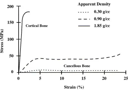
near linear stress-strain curve, aside from a slight toe-region at low strain. This yields an assumed uniform and unique Young's modulus in each loading direction (Figure 1.2).49
Similarly, cancellous bone exhibits anisotropic and viscoelastic behavior, but the apparent mechanical properties are highly variable, a function of apparent density, and consequently change with anatomic location.18 Additionally, cancellous stress-strain relationships show a varying profile, in which the bone first exhibits a linear response, followed by plastic collapse, in which the stress remains relatively constant for increasing strain, before exhibiting a second linear response and fracture (Figure 1.2). This region of constant stress occurs due to the porous trabeculae (internal porous structure of the bone) failing before compromising the entire structure. It is this varying density distribution that undergoes constant remodeling allowing bone to adaptively react to variations in loading that may result from changes in muscle strength, injury, or disease.
Bone structure is also a function of diet, age, lifestyle and activity level. Therefore, cross-population material property characteristics are difficult to obtain.
Cortical Bone
Figure 1.2: Stress-strain curves for bone as a function of apparent density.49 Cancellous Bone
Cortical Bone
Strain (%)
S
tr
es
s
(M
P
a)
0 5 10 15 20 25
Apparent Density
200
150
100
50
0
Additionally, as previously discussed, cancellous bone properties are a function of
anatomic location and loading, resulting in difficulty in the development of equations that accurately represent material properties. Carter and Hayes10 first suggested a commonly accepted relationship between the apparent density of cancellous bone and Young’s modulus that was strain rate dependent; however, it has since been suggested that strain rate dependency is negligible, and therefore, the modulus can be assumed independent of strain rate.73
Current finite element studies of the shoulder make use of a wide range of strain rate independent modulus equations.8,13,26,27,34,65,75 A validated modulus equation for the shoulder does not exist, and as a result, these equations may not accurately represent the narrow range of bone densities found in the glenoid or variations due to osteoarthritis. As part of this thesis the modulus equation developed by Carter and Hayes10 (Equation 1.1),
which is sensitive to slight changes in cancellous apparent density in the low density range,4 was chosen. Cortical bone exhibits a near linear modulus, with an average apparent density ≥1.85g/cc, allowing for an assumed homogeneous modulus (E= 20 000 MPa).4
𝑬 = 𝟐𝟖𝟕𝟓 ∙ 𝝆
𝒂𝒑𝒑𝟑[𝐌𝐏𝐚]
Equation 1.11.1.4 In-Vivo Bone Density Measurements
1.1.4.1 Dual energy x-ray absorptiometry (DEXA)
Dual energy x-ray absorptiometry (DEXA) is the most common quantitative method to measure BMD and diagnose osteoporosis. This technology uses low dose x-ray radiation to measure an ‘areal’ or area density in g/cm2.45 This method allows for the
determination of fracture risk in many patients; however, the areal measurement is a sum of both the cancellous and cortical bone in a region, which present some difficulty in analysis.25,45 Due to this reality, it is possible that large patients with low BMD and small patients with high BMD have similar results when scanned with a DEXA scanner, due to the contribution of soft tissues in the areal density measurements. This method must be done at the discretion of an experienced clinician/technician, and the results interpreted subjectively.
In many research applications, a higher resolution, with greater distinction
between cortical and cancellous bone is necessary. In these cases, DEXA fails to provide the required quantitative results and is best used as a clinical tool or in studies assessing fracture risk that are not sensitive to variations that may occur due to the areal BMD measurements.
1.1.4.2 Computed Tomography Hounsfield Units
Computed tomography scanners are used as a diagnostic and increasingly common research tool to assess the internal structure of patients or subjects. The process works by collecting a stack of x-ray projections around a patient/subject and calculating the
attenuation of internal tissues. Computer algorithms are used to align the images and assign intensity values based on the x-ray attenuation, saving the images in a common DICOM (digital imaging and communications in medicine) format. Modern multi-slice CT scanners are calibrated using the Hounsfield scale, which averages the x-ray
pixels), in the anatomical sagittal, coronal, and axial planes. The resultant intensity values represent different tissues and are scaled based on the supplied cathode energy. The range of HU values are from -1024 to +3071 with approximate values of water and air of 0 and -1000 HU, respectively.
𝑯𝑼 =
𝝁− 𝝁𝒘𝒂𝒕𝒆𝒓𝝁𝒘𝒂𝒕𝒆𝒓− 𝝁𝒂𝒊𝒓
𝒙 𝟏𝟎𝟎𝟎
Equation 1.2Since the slice increment and thickness of each image is known, software algorithms can determine voxel intensities (three-dimensional pixels). By thresholding the intensity value of each voxel, using manual segmentation methods and spatial
information provided, materials can be separated from the CT scan data. This information allows for the reconstruction of bone into three-dimensional computer models with accuracy as good as a patient’s physical bone.7 The resolution of clinical CT scanners is
limited in order to balance radiation dose with requirements for accurate diagnosis. In many modern research applications, micro-CT scanners capable of increases in resolution of 10-100 times greater than clinical CT scanners, are required. As part of this thesis, clinical CT scans were found to be sufficient, and were used to be consistent with the diagnostic tools currently available to clinicians in a modern hospital setting.
1.2 THE GLENOHUMERAL JOINT
1.2.1 Osseous Anatomy
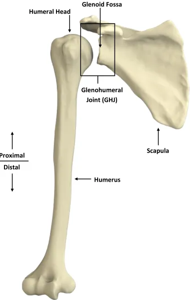
Figure 1.3: Three-dimensional reconstructions of the humerus and scapula
Humerus
Scapula
Glenohumeral
Joint (GHJ)
Glenoid Fossa
Distal
Proximal
due to its lower modulus than the underlying bone. This difference in curvature results in a localized contact area of the humeral head on the glenoid, and allows for the large and nearly impingement free range of motion of the GHJ. Theoretically, this may also allow relative translation of the humeral head across the glenoid, which could compromise joint stability.5,6,40 With sufficient soft tissue balance across the GHJ, it has been shown that
stability is maintained and relative humeral translations are minimized.28,35,51,66 However, pathologic soft tissue deficiency in the GHJ may result in increased translation, or
subluxation of the humeral head, leading to cartilage degradation and bony erosion.23,67,68
Furthermore, this subluxation may alter the joint contact area, with resultant loading changes and possible bone remodeling. Pathologic joint deficiency will be further discussed in section 1.3.
1.2.2 Glenoid Anatomic Parameters
Anatomic parameters on the scapular articulation of the glenohumeral joint, the glenoid, allow for characterization of the articulation. These parameters assist in the assessment of joint pathology, morphology and may assist in the selection of devices required for joint replacement surgeries. Additionally, these parameters are essential in the design of glenoid components that act to restore and mimic native joint anatomy. The three parameters discussed here include the glenoid height, the glenoid width, and the glenoid version (Figure 1.4).
Glenoid height is measured as the most superior to inferior points on the glenoid surface in a plane sagittal to the glenoid articular surface (Figure 1.4-A).37 Due to the inherent ‘pear shape’ of the glenoid, two width measurements are typically reported – a superior width and an inferior width. These two measurements are measured as a
Height
Inferior
Width
Superior
Width
Inferior
Superior
Lateral
Medial
Posterior
Anterior
A
B
C
Figure 1.4: Anatomic Parameters of the Glenoid
The glenoid height is measured as the most superior to inferior points on the glenoid surface (A). The glenoid width is measured as the most anterior to posterior points, superiorly and inferiorly (B). The glenoid version is the angle of the glenoid relative to the line/plane perpendicular to the scapular coronal axis (C), and is positive in a counter-clockwise direction.
Scapular Coronal Axis
(Figure 1.4-C).21,38 This measurement is referred to as anteversion if the angle is positive in the counter-clockwise direction, and retroversion if negative. Recent studies have suggested that within the population, the glenoid in natively retroverted 1 ± 3°, which increases the difficulty in restoring native anatomy in shoulder replacement procedures, by contributing to joint instability.44
1.3 Glenohumeral Joint Deficiency/Pathology
Glenohumeral joint (GHJ) deficiency as related to this thesis focuses primarily on glenohumeral osteoarthritis (OA). Primary OA is idiopathic, while secondary OA may be caused by injury, disease, genetics or many other factors. Osteoarthritis is non-systemic and is characterized by joint inflammation with associated pain. As OA progresses, bony growth occurs, known as osteophytes, which limit joint motion and result in pain.
Similarly, the loss of motion of the joint often results in the calcification of associated ligaments and tendons due to lack of use. Bony growths and calcification occurs due to uncontrolled bone remodeling brought on by altered loading patterns, as well as unknown biological factors.
Typically uncharacteristic of OA, bony erosions occur on the glenoid as articular cartilage degrades. This erosion can occur uniformly across the glenoid surface,
producing a symmetric erosion pattern, or may occur asymmetrically, due to subluxation of the humeral head.23,67,68 It is unknown as to whether subluxation leads to the
Figure 1.5: Axial radiographs of five glenoid erosion morphologies classified by Walch et al.68
Type A1 Type A2
Type B1 Type B2
progression of OA and allow for the selection of joint replacements that act to restore native joint anatomy.
1.3.1 Surgical Interventions for GHJ Deficiency
Joint replacement surgeries are performed when joint pain and loss of function has reached a level that cannot be improved with non-surgical treatments. Specific to each individual patient, a variety of surgical options exist to improve joint function and reduce pain. Depending on the condition of soft tissues, progression of OA, age, health, etc., surgical outcomes are highly variable.16,20,36,57 In all surgical cases, preservation of bone stock is essential for implant fixation and stability and to ensure that sufficient bone remains in case of future need for revision surgeries.69,71
1.3.1.1 Anatomic total shoulder arthroplasty
Anatomic total shoulder arthroplasty (TSA) replaces both the proximal humerus and the glenoid with artificial components that act to mimic native anatomy. In
Figure1.6: Depuy® Global® APG+ standard glenoid component
Humeral Component
Standard Glenoid Component
Figure1.7: Implanted components in anatomic total shoulder arthroplasty
In more advanced cases of osteoarthritis, such as those with posterior bone loss, the surgical intervention may require a bone graft to be placed between the implant and eroded glenoid to reconstruct the native joints articular geometry. Similar to this method, augmented glenoid components are commercially available that use a step or wedge on the medial surface of the implant to "fill" the region of eroded bone. These methods are typically used when acquired retroversion of the glenoid is greater than 15°, as this morphology cannot be corrected with asymmetric reaming alone.12
1.3.1.1.1 Augmented glenoid components
Augmented glenoid components are a modified version of anatomic total shoulder arthroplasty glenoid components, designed specifically to minimize bone removal in shoulders with posterior glenoid erosion. The term ‘augmented’ refers to an extension or thickening of the posterior aspect of the implant back. This thickening is designed to build up the asymmetrically eroded posterior region in order to restore the native
orientation of the articulation. These implants correct to the desired version angle without the requirement for asymmetric or eccentric 'high-side' reaming of the deficient glenoid.
There are currently two implant manufacturers producing augmented glenoid components for clinical use, and one manufacturer marketing an augmented component for imminent availability. All three implants orient the augment about the central axis of the implant. This design assumes posterior bone loss occurs with a maximum directed toward the 9 o’clock position in a right shoulder. If bone loss does not occur in this manner, there may be additional bone removal required in the superior aspect of the glenoid in order to facilitate implantation (Figure 1.8). Furthermore, if bone loss
Figure 1.8: Three-dimensional reconstructions of a patient scapula with posterior glenoid erosion
Intact scapula (left). Depiction of the erosion ridge (middle). Implanted augmented glenoid component illustrating regions requiring additional bone removal and unsupported by implant material (right).
Erosion Ridge
Additional Bone Reaming Required
Central Axis of Augmented Implant
Not Supported by Implant Material
1.3.3.1.1.1 DePuy® Global® Steptech® APG
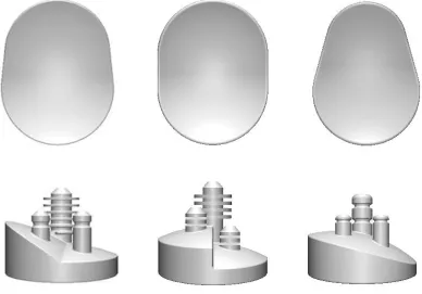
The Global® Steptech® Anchor Peg Glenoid (APG) is a variation of the standard Global® APG+ Implant System (Figure 1.5). The Steptech® uses a 3, 5 or 7 mm step from the implants backside encompassing the entire posterior hemisphere (Figure 1.9). For each step height, the implants are available in five sizes according to bearing
diameters of 40, 44, 48, 52 and 56 mm. These implants are sized according to the glenoid size and humeral component required for each individual patient. This implant reduces joint medialization by minimizing eccentric 'high-side,' anterior reaming. The stepped design mimics the articular backside geometry of commonly used all-polyethylene non-augmented implants, reducing the contribution of shear forces experienced by the cemented fixation pegs. According to Depuy, the Global® Steptech® APG reduces the need for bone grafts, asymmetric (eccentric) reaming, thereby reducing joint
medialization and removal of healthy bone.17
1.3.3.1.1.2 Exactech® Equinoxe® Posterior Augment Glenoid
The Equinoxe® Posterior Augment Glenoid acts to reduce anterior cortical bone removal for posterior eroded glenoids with retroversion greater than six degrees.19 The implant is anatomically 'pear' shaped with a smaller superior diameter and larger inferior diameter (Figure 1.9). This implant uses a full-wedge design with an 8° wedge angle from posterior to anterior. Although not currently marketed, the company has also recently tested models with 12° and 16° wedge angles.54 The implants are available in small, medium, large, and extra-large sizes that act to maximize glenoid surface area, while reducing the risk of implant overhang. Exactech also markets metal-backed
Figure 1.9: Three commercially available augmented glenoid component designs
1.3.3.1.1.3 Tornier® Posterior Augment Glenoid
The Posterior Augment Glenoid (PAG) is the newest augmented glenoid implant and is expected to be commercially available in 2015. The PAG can be thought of as a hybrid of the Steptech® and Equinoxe® PAG as it uses a wedge symmetric about the implants central axis that encompasses the entire posterior hemisphere (Figure 1.9). This implant has wedge angles of 15°, 25° and 35° and is available in small, medium, large and extra-large sizes. The design acts to minimize reaming by better mimicking the degree of retroversion exhibited in asymmetric glenoid erosion.
1.3.1.2 Reverse Total Shoulder Arthroplasty
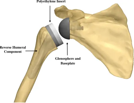
Reverse total shoulder arthroplasty (RTSA) is an effective treatment for rotator cuff arthropathy or in cases that cannot be effectively managed with anatomic total shoulder arthroplasty.59 The alteration of the native muscle balance across the
glenohumeral joint (GHJ), as seen in many pathologic GHJ diseases, contributes to the inherent instability of glenoid posterior erosion. 59 As a result RTSA is an attractive treatment option in many of these multifactor cases. Similarly, RTSA is most commonly used in revision surgery due to the lack of sufficient glenoid bone stock remaining for effective implant fixation and support. It may also be used in cases of trauma when significant disruption to soft tissues or bone support has occurred.
Polyethylene Insert
Glenosphere and Baseplate Reverse Humeral
Component
Figure 1.10: Implanted components in reverse total shoulder arthroplasty
1.3.1.3 Hemi-Arthroplasty
Hemi-arthroplasty, also known as the ‘ream and run procedure,’ acts to minimize bone surface removal for patients requiring joint replacement. In this procedure a
standard humeral head component it utilized as in the TSA procedure previously described (Section 1.3.1.1). However, on the glenoid surface only minimal reaming is performed to achieve a concentric glenoid surface.41,42 The procedure has been shown to be effective in the treatment of glenohumeral osteoarthritis,24,43,47 and because it does not implant a glenoid component or bone graft, it may be a more effective procedure for younger patients who may have a future need for revision surgeries.
Resurfacing hemi-arthroplasty is an even more conservative bone preservation procedure that retains the humeral head and uses a humeral component that encompasses only the articular surface of the humeral head. Again, the glenoid is minimally reamed to match the articular curvature of the humeral component, preserving the most bone.
1.4
FINITE ELEMENT MODELLING OF THE SHOULDER
In orthopaedics, advancements in imaging technologies and medical imaging software now allow for accurate reconstruction of bone geometry (primarily from computed tomography data). In computational biomechanical modeling, three-dimensional models of bone can be created, bone specific heterogeneous material properties can be defined and physiological loads can be simulated. Furthermore, using these three-dimensional models, modifications can be made to allow for the virtual implantation of medical devices. This allows us to critically evaluate the loading scenario imposed by joint replacements prior to implantation in-vivo.
Figure 1.11: Discretized scapular model for finite element analysis
mechanics that only allow for the application of material and governing equations over the geometry as a whole, the finite element method allows for individual material
properties to be defined to specific elements and the governing equations to be applied in an element by element or node by node basis. This application of forces and constraints provides the user with a site specific analysis of the internal loading scenario of the discretized model.
A large number of studies have explored shoulder biomechanics using the finite element method. These range from comparatively simple studies discussing model
generation,11 stress and strain analysis 8,13,27,39,61 implant thickness,63 humeral and glenoid component conformity,65,75 and micromotion,72 to seemingly complex studies that assess implant bone remodeling and in-growth,1,9,58,62 and cement mantle stresses.32,33,50,64 An
inherent discontinuity in all previous FE models of the shoulder is that accurate and validated equations for site specific material properties do not exist. The apparent density of bone and CT intensity have been correlated10,52,53,55 and these relationships used to develop equations that relate to mechanical properties.3,4,29,48 However, it has been suggested that these relationships, and therefore the equations that are experimentally developed, are site-specific.48 It has also been suggested that accurate assessment of bone density increases the accuracy of subject-specific FE models.56 It follows that all previous shoulder FE studies have used a variation of equations developed for alternative anatomic locations, which could have a dramatic affect on the validity of FE analysis.
Although studies have begun to assess augmented glenoid components using FE methods,31 the distribution of bone densities in osteoarthritic joints may vary greatly from the non-pathologic joint, increasing the error in using non-site-specific material mapping. A handful of studies have decreased the material properties in their simulated
osteoarthritic (OA) groups by a given factor.31,50 However, it is likely that these models
1.5
RATIONALE
Total shoulder arthroplasty (TSA) has been shown to be effective in pain relief for up to 93% of patients.46 The number of TSA procedures performed in the U.S. is
expected to increase by almost 40% from 2005 to 201514 (with similar predictions in
Canada). Improving the long-term outcomes of TSA may significantly reduce future health care costs. Positive outcomes rely on surgical technique to ensure implant
placement matches implant design. Pre-operative planning software and patient-specific guides now exist to assist surgeons in the optimal placement of the glenoid component, showing early success compared to traditional techniques.30,70 Although these guides may improve implant placement, currently marketed glenoid implants show concerning long-term outcomes, primarily from implant loosening.15 Furthermore, the complex scenario presented in asymmetrically eroded glenoids increase the risk of implant failure by compromising underlying bone support, fixation and stability. Augmented glenoid components exist to account for these complexities; however current design may not match the morphology of the joint. This may result in malaligned component placement or compromise desired component fixation.
Although first classified by Walch et al.68 fifteen years ago, little is known about asymmetric glenoid erosion or its affect on glenoid component stability. With current advancements in medical imaging and associated software, our understanding of this joint morphology has dramatically improved in recent years. Pre-operative computed
tomography scans have become a common pre-operative tool to allow surgeons to improve and optimize their surgical plan. These scans provide a vast amount of data that can be utilized to assess and classify previously unknown characteristics of pathologic joint deformity.
Computational methods now exist for us to critically evaluate the internal and external loading imposed on bone under varying parameters. This has the potential to significantly improve the long-term outcomes of joint replacement components by
can be created that closely mimic the loading scenario imposed by joint replacement surgeries.
1.6
PROJECT OBJECTIVES AND HYPOTHESES
The overall goal of this thesis was to quantify the morphology of the osteoarthritic glenohumeral joint (GHJ) in order to better understand the mechanisms that compromise joint replacement fixation, stability and support. Current implant designs rely heavily on previously marketed component designs that have successfully passed regulatory
approval. However, the extent to which current designs are based on research that accounts for joint deficiency and acts to reproduce native joint anatomy is unknown. These inherent flaws may compromise current joint replacements, leading to premature failure. In the pursuit of better understanding the mechanisms of GHJ replacement failure, four specific objectives were explored as part of this research. The corresponding hypotheses follow each objective.
Objective 1: To characterize the subarticular glenoid bone density in three-dimensionally reconstructed scapulae of patients with symmetric and asymmetric glenoid erosion. In order to measure glenoid bone density a quadrant coordinate system must first be developed to ensure consistent measurement regions between patients. This will allow for regional bone density variations to be determined on the basis of Hounsfield Units (HU) in four quadrants and two depths from the articular surface. The porosity of the regions can also be compared using a volume subtraction method in the same regions.
Additionally, the density and porosity in anterior and posterior regions separated by the erosion in asymmetrically eroded glenoids can be compared using the same method as the quadrants.
in the posterior aspects and specifically, the posteroinferior quadrant of asymmetrically eroded glenoids as compared to symmetrically eroded glenoids.
Objective 2: To determine the orientation, position and surface area of bone loss in patients with asymmetric glenoid erosion.
Glenoid posterior erosion results in a clearly visible ridge of eroded bone when three-dimensionally reconstructed or in-vivo. In order to quantify the symmetry of this erosion, a clinically relevant two-dimensional sagittal plane analysis can be utilized; making use of points collected on three-dimensional scapulae reconstructions. The collected points must be validated between observers to ensure consistency in results.
Hypothesis 2: It is hypothesized that contrary to current commercially available augmented glenoid components, erosion in asymmetrically eroded glenoids is not symmetric about the superoinferior axis of the glenoid.
Objective 3: To quantify and compare the volume of bone removed and the quality of underlying bone with three augmented glenoid component designs.
Virtual models constructed using computer aided design (CAD) software to the exact dimensions of three currently marketed glenoid components (wedge, posterior-step and full-wedge) will be virtually implanted in three-dimensional scapulae of patients with asymmetric glenoid erosion by an experienced shoulder surgeon. The quality of bone in anterior and posterior aspects 2.5 mm below each implant will be assessed on the basis of bone density in HU and porosity using a similar method to Objective 1.
Hypothesis 3: It is hypothesized that the posterior wedge implant more accurately represents posterior erosion and will therefore result in the least bone removal for optimal component placement. It is expected that significant differences in the bone density and porosity will exist between anterior and posterior regions with all three augmented component designs.
This investigation will expand on the results from objective 3 by providing node based strain data that will be used to assess the strain field experienced in the bone underlying each glenoid component. This strain field will be used to determine if strain is correlated to bone density in different regions.
Hypothesis 4: It is hypothesized that the implants that remove the least bone adjacent to the erosion will exhibit less strain and therefore provide a greater underlying surface for early implant support and fixation.
1.7
THESIS OVERVIEW
1.8
REFERENCES
1. Andreykiv A, Prendergast PJ, van Keulen F, Swieszkowski W, Rozing PM. Bone ingrowth simulation for a concept glenoid component design. J Biomech
2005;38(5):1023–33. doi:10.1016/j.jbiomech.2004.05.044
2. Ashby MF. Materials Selection in Mechanical Design. Burlington, MA: Elsevier Ltd; 2011.
3. Austman RL, Milner JS, Holdsworth DW, Dunning CE. The effect of the density-modulus relationship selected to apply material properties in a finite element model of long bone. J Biomech 2008;41(15):3171–6.
doi:10.1016/j.jbiomech.2008.08.017
4. Austman RL, Milner JS, Holdsworth DW, Dunning CE. Development of a
customized density–modulus relationship for use in subject-specific finite element models of the ulna. Proc Inst Mech Eng Part H J Eng Med 2009;223(6):787–794. doi:10.1243/09544119JEIM553
5. Bey MJ, Kline SK, Zauel R, Kolowich P a, Lock TR. In Vivo Measurement of Glenohumeral Joint Contact Patterns. EURASIP J Adv Signal Process;2010:2–7. doi:10.1155/2010/162136
6. Boyer PJ, Massimini DF, Gill TJ, Papannagari R, Stewart SL, Warner JP, et al. In vivo articular cartilage contact at the glenohumeral joint: preliminary report. J Orthop Sci 2008;13(4):359–65. doi:10.1007/s00776-008-1237-3
7. Bryce CD, Pennypacker JL, Kulkarni N, Paul EM, Hollenbeak CS, Mosher TJ, et al. Validation of three-dimensional models of in situ scapulae. J Shoulder Elbow Surg 2008;17(5):825–32. doi:10.1016/j.jse.2008.01.141
8. Büchler P, Ramaniraka NA, Rakotomanana LR, Iannotti JP, Farron A. A finite element model of the shoulder: application to the comparison of normal and osteoarthritic joints. Clin Biomech 2002;17(9-10):630–639. doi:10.1016/S0268-0033(02)00106-7
9. Campoli G, Weinans H, van der Helm F, Zadpoor AA. Subject-specific modeling of the scapula bone tissue adaptation. J Biomech 2013;46(14):2434–41.
doi:10.1016/j.jbiomech.2013.07.024
11. Cattaneo PM, Dalstra M, Frich LH. A three-dimensional finite element model from computed tomography data: A semi-automated method. Proc Inst Mech.Eng Part H J Eng Med;215(2):203–212. doi:10.1243/0954411011533760
12. Clavert P, Millett PJ, Warner JJP. Glenoid resurfacing: what are the limits to asymmetric reaming for posterior erosion? J. Shoulder Elbow Surg
2007;16(6):843–8. doi:10.1016/j.jse.2007.03.015
13. Couteau B, Mansat P, Estivalèzes É, Darmana R, Mansat M, Egan J. Finite
element analysis of the mechanical behavior of a scapula implanted with a glenoid prosthesis. Clin Biomech 2001;16(7):566–575.
doi:10.1016/S0268-0033(01)00029-8
14. Day JS, Lau E, Ong KL, Williams GR, Ramsey ML, Kurtz SM. Prevalence and projections of total shoulder and elbow arthroplasty in the United States to 2015. J Shoulder Elbow Surg 2010;19(8):1115–20. doi:10.1016/j.jse.2010.02.009
15. Denard PJ, Raiss P, Sowa B, Walch G. Mid- to long-term follow-up of total shoulder arthroplasty using a keeled glenoid in young adults with primary glenohumeral arthritis. J Shoulder Elbow Surg 2013;22(7):894–900. doi:10.1016/j.jse.2012.09.016
16. Denard PJ, Walch G. Current concepts in the surgical management of primary glenohumeral arthritis with a biconcave glenoid. J Shoulder Elbow Surg 2013;22(11):1589–98. doi:10.1016/j.jse.2013.06.017
17. Global Steptech Design Rationale and Surgical Technique. Depuy Orthopaedics. 2011.
18. Ethier CR, Simmons CA. Introductory Biomechanics: From Cells to Organisms. Cambridge University Press; 2007
19. Equinoxe Operative Technique Addedum Exactech Inc. 2011.
20. Farron A, Terrier A, Büchler P. Risks of loosening of a prosthetic glenoid implanted in retroversion. J Shoulder Elbow Surg 2006;15(4):521-526
21. Friedman RJ, Hawthorne KB, Genez BM. The use of computerized tomography in the measurement of glenoid version. J Bone Joint Surg Am 1992;74(7):1032–7. 22. Galante J, Rostoker W, Ray RD. Physical properties of trabecular bone. Calcif
Tissue Res 1970;5(1):236–246. doi:10.1007/BF02017552
24. Gilmer BB, Comstock BA, Jette JL, Warme WJ, Jackins SE, Matsen FA. The prognosis for improvement in comfort and function after the ream-and-run arthroplasty for glenohumeral arthritis: an analysis of 176 consecutive cases. J Bone Joint Surg Am 2012;94(14):e102. doi:10.2106/JBJS.K.00486
25. Guglielmi G. Osteoporosis and Bone Densitometry Measurements. Berlin, Heidelberg: Springer Berlin Heidelberg; 2013 doi:10.1007/978-3-642-27884-6 26. Gunther SB, Lynch TL, O’Farrell D, Calyore C, Rodenhouse A. Finite element
analysis and physiologic testing of a novel, inset glenoid fixation technique. J Shoulder Elbow Surg 2012;21(6):795–803. doi:10.1016/j.jse.2011.08.073 27. Gupta S, Helm F Van der, Keulen F Van. Stress analysis of cemented glenoid
prostheses in total shoulder arthroplasty. J Biomech 2004
28. Harryman D, Sidles J, Clark J. Translation of the humeral head on the glenoid with passive glenohumeral motion. J Bone Joint Surg 1990;72(9):1334-1343
29. Helgason B, Perilli E, Schileo E. Mathematical relationships between bone density and mechanical properties: a literature review. Clin Biomech 2008;23(2):135-146 30. Hendel M, Bryan J. Comparison of Patient-Specific Instruments with Standard
Surgical Instruments in Determining Glenoid Component Position: A Randomized Prospective Clinical Trial. J Bone Joint Surg 2012;94(23):2167-2175
31. Hermida J. Augmented wedge-shaped glenoid component for the correction of glenoid retroversion: a finite element analysis. J Shoulder Elbow Surg
2014;23(3):347-354
32. Hopkins, Andrew R., et al. Wear in the prosthetic shoulder: association with design parameters. J Biomech Eng 2007; 129(2): 223-230.
33. Hopkins, Andrew R., et al. Wear in the prosthetic shoulder: association with design parameters. J Biomech Eng 2007; 129(2): 223-230.
34. Hopkins AR, Hansen UN, Amis A. Finite element models of total shoulder replacement: Application of boundary conditions. Comput Methods Biomech Biomed Engin;8(1):39–44. doi:10.1080/10255840500075205
35. Howell S, Galinat B, Renzi A, Marone P. Normal and abnormal mechanics of the glenohumeral joint in the horizontal plane. J Bone Jt Surg 1988;70(2):227-232 36. Hsu JE, Ricchetti ET, Huffman GR, Iannotti JP, Glaser DL. Addressing glenoid
37. Iannotti JP, Gabriel JP, Schneck SL, Evans BG, Misra S. The normal glenohumeral relationships. An anatomical study of one hundred and forty shoulders. J Bone Joint Surg Am 1992;74(4):491–500.
38. Kwon Y, Powell K, Yum J. Use of three-dimensional computed tomography for the analysis of the glenoid anatomy. J Shoulder Elbow Surg 2005; 14(1):85-90 39. Mansat P, Briot J, Mansat M, Swider P. Evaluation of the glenoid implant survival
using a biomechanical finite element analysis: influence of the implant design, bone properties, and loading location. J. Shoulder Elbow Surg 2007;16(3):S79-S83 40. Massimini DF, Li G, Warner JP. Glenohumeral contact kinematics in patients after
total shoulder arthroplasty. J Bone Joint Surg Am 2010;92:916–926. doi:10.2106/JBJS.H.01610
41. Matsen F, Warme WJ, Jackins SE. Can the Ream and Run Procedure Improve Glenohumeral Relationships and Function for Shoulders With the Arthritic Triad? Clin Orthop Rela. Res 2014;2–9. doi:10.1007/s11999-014-4095-7
42. Matsen F, Lippitt S. Current Technique for the Ream-and-Run Arthroplasty for Glenohumeral Osteoarthritis. J Bone Jt Surg 2012;e20-21
43. Matsen F, Warme WJ, Jackins SE. Can the Ream and Run Procedure Improve Glenohumeral Relationships and Function for Shoulders With the Arthritic Triad? Clin Orthop Rela. Res 2014;2–9. doi:10.1007/s11999-014-4095-7
44. Matsumura N, Ogawa K, Kobayashi S, Oki S, Watanabe A, Ikegami H, et al. Morphologic features of humeral head and glenoid version in the normal glenohumeral joint. J Shoulder Elbow Surg 2014;23(11):1724–30. doi:10.1016/j.jse.2014.02.020
45. Mazess R, Barden H. Dual-energy x-ray absorptiometry for total-body and regional bone-mineral and soft-tissue composition. Am J Clin
Nutr 1990;51(6):1106-1112
46. McCoy S, Warren R, III HB. Total shoulder arthroplasty in rheumatoid arthritis. J Arthoplasty;4(2):105-113
47. Mercer D, Gilmer B. A quantitative method for determining medial migration of the humeral head after shoulder arthroplasty: preliminary results in assessing glenoid wear at a minimum of. J Shoulder Elbow Surg 2011; 20(2):301-307 48. Morgan E, Bayraktar H, Keaveny T. Trabecular bone modulus–density
49. Nordin M, Frankel V. Basic biomechanics of the musculoskeletal system. 2001. Lippincott Williams & Wilkins
50. Patel R, Wright T, Gao Y. Load transfer after cemented total shoulder arthroplasty. J Shoulder Elbow Surg 2014; In-Press
51. Poppen N, Walker P. Normal and abnormal motion of the shoulder. J Bone Jt Surg 1976;58(2):195-201
52. Rho J, Hobatho M, Ashman R. Relations of mechanical properties to density and CT numbers in human bone. Med Eng Phys 1995;17(5):347-355
53. Rice J, Cowin S, Bowman J. On the dependence of the elasticity and strength of cancellous bone on apparent density. J Biomech 1988; 21(2):155-168
54. Roche C, Diep P. Biomechanical Impact of Posterior Glenoid Wear on Anatomic Total Shoulder Arthroplasty. Bull Hosp Joint Disease 2013;71:S5-11
55. Schaffler M, Burr D. Stiffness of compact bone: effects of porosity and density. J Biomech 1988;21(1):13-16
56. Schileo E, Dall’Ara E, Taddei F. An accurate estimation of bone density improves the accuracy of subject-specific finite element models. J Biomech
2008;41(11):2483-2491
57. Sears BW, Johnston PS, Ramsey ML, Williams GR. Glenoid Bone Loss in Primary Total Shoulder Arthroplasty. J Am Acad Orth Surg 2012;20(9):604-613 58. Sharma GB, Debski RE, McMahon PJ, Robertson DD. Adaptive glenoid bone
remodeling simulation. J Biomech 2009;42(10):1460–8. doi:10.1016/j.jbiomech.2009.04.002
59. Smithers C, Young A, Walch G. Reverse shoulder arthroplasty. Curr Rev Musculoskelet Med 2011;4(4):183-190
60. Sophia Fox AJ, Bedi A, Rodeo SA. The basic science of articular cartilage: structure, composition, and function. Sports Health 2009;1(6):461–8. doi:10.1177/1941738109350438
61. Stone K, Grabowski J, Cofield R. Stress analyses of glenoid components in total shoulder arthroplasty. J Shoulder Elbow Surg 1999; 8(2):151-158
63. Terrier A, Brighenti V, Pioletti D, Farron A. Importance of polyethylene thickness in total shoulder arthroplasty: A finite element analysis. Clin Biomech
2012;27(5):443-448
64. Terrier A, Büchler P, Farron A. Bone–cement interface of the glenoid component: stress analysis for varying cement thickness. Clin Biomech 2005;20(7):710-717 65. Terrier A, Büchler P, Farron A. Influence of glenohumeral conformity on glenoid
stresses after total shoulder arthroplasty. J Shoulder Elbow Surg 2006;15(4):515-520
66. Veeger H. The position of the rotation center of the glenohumeral joint. J Biomech 2000; 33(12):1711-1715
67. Walch G, Ascani C. Static posterior subluxation of the humeral head: an
unrecognized entity responsible for glenohumeral osteoarthritis in the young adult. J Shoulder Elbow Surg 2002; 11(4):309-314
68. Walch G, Badet R, Boulahia A, Khoury A. Morphologic study of the Glenoid in primary glenohumeral osteoarthritis. J Arthroplasty 1999;14(6):756–760. doi:10.1016/S0883-5403(99)90232-2
69. Walch G, Moraga C. Results of anatomic nonconstrained prosthesis in primary osteoarthritis with biconcave glenoid. J Shoulder Elbow Surg 2012;21(11):1526-1533
70. Walch G, Vezeridis P, Boileau P. Three-dimensional planning and use of patient-specific guides improve glenoid component position: an in vitro study. J
Shoulder Elbow Surg 2014; In-Press
71. Walch G, Young A, Boileau P. Patterns of loosening of polyethylene keeled glenoid components after shoulder arthroplasty for primary osteoarthritis. J Bone Joint Surg 2012;94(2):145-150
72. Wang V, Krishnan R. Biomechanical evaluation of a novel glenoid design in total shoulder arthroplasty. J Shoulder Elbow Surg 2005; 14(1):S129-S140
73. Weinans H, Huiskes R, Grootenboer HJ. Effects of material properties of femoral hip components on bone remodeling. J Orthop Res 1992;10(6):845–53
doi:10.1002/jor.1100100614
74. Wolff J. The law of bone remodeling. Verlag von August Hirchwald. Berlin. 1892 75. Zhang J, Yongpravat C, Kim H. Glenoid articular conformity affects stress
CHAPTER 2 -
REGIONAL BONE DENSITY
VARIATIONS IN OSTEOARTHRTIC GLENOIDS: A
COMPARISON OF SYMMETRIC AND
ASYMMETRIC (TYPE B2) EROSION PATTERNS
OVERVIEW: Subchondral bone density variations are known to occur as the result of cartilage degeneration in osteoarthritic joints. In the shoulder, glenoid bone erosion uncharacteristic of osteoarthritis is often observed. In cases where erosion occurs symmetrically, the resulting bone density is thought to be uniform across the surface of the glenoid. However, in cases with asymmetric erosion, we hypothesized that bone density is not uniform across the glenoid surface, due to the altered kinematics of the joint and the resultant altered stress distribution. This chapter evaluated patients with glenohumeral osteoarthritis with symmetric erosion (n=25) and asymmetric erosion (n=25) in order to characterize regional bone density variations. Porosity of the bone was also quantified using a void ratio method.1
2.1 INTRODUCTION:
In patients with osteoarthritis undergoing total shoulder arthroplasty, the long-term survivability of cemented polyethylene glenoid components have been
concerning.5,7,12,31 Typically, failures are described as multi-factorial;1,13 however, aseptic
loosening of glenoid components remains a leading cause of revision surgery.2,9,23,32
Initial glenoid fixation is theorized to be an important factor in improving implant survivability. Additionally, it has been reported that preservation of the dense sclerotic remaining bone of the arthritic glenoid may be an important factor in decreasing implant migration and failure.29
Walch et. al. recommend minimal glenoid reaming to preserve the dense sclerotic “subchondral” bone to provide uniform underlying support of the implant.29,30 Many
other studies have often referred to the glenoid bone as subchondral;”16,18,20,24,25,34 however, in osteoarthritis the chondral layer is often partially or completely absent. As such, we propose this glenoid bone be referred to as “subarticular” rather than
“subchondral”.
In patients with symmetric glenoid wear (Figure 2.1A), the dense sclerotic bone is theorized to be uniformly distributed over the glenoid articular surface to allow support of the implant to limit medial or tilting migration. However, there is little data specific to the arthritic glenoids structure to determine if the bone density is evenly distributed or if there are regional variations. Additionally, in cases classified by Walch et al.28 as type
B2, the effect of asymmetric wear with a resultant biconcave glenoid (Figure 2.1B) on the regional bone density characteristics is unknown. Preservation of the dense sclerotic bone is technically easier when the glenoid is symmetrically eroded. However, when an
asymmetrically posteriorly eroded glenoid requires asymmetric reaming, or an
augmented implant to correct retroversion, the regional bone quality characteristics of the glenoid are unknown
Figure 2.1: Representative axial CT images of glenoid erosion associated with osteoarthritis.
understanding the location of the highest quality dense glenoid bone may potentially guide the design of augmented glenoid components that utilize preparation techniques that minimize quality bone removal to maximize glenoid component support and fixation. Minimizing structural bone removal has the potential to increase the long-term
survivability of glenoid implants.
The purpose of this study was to characterize regional bone density and porosity variations in osteoarthritic glenoids. Our first objective was to determine if bone density and porosity in a symmetrically eroded glenoid is uniformly distributed. Our second objective was to determine if glenoids with asymmetric posterior biconcavity have regional variations in bone density. We hypothesized, based on clinical experience that altered glenohumeral contact kinematics in biconcave glenoids leads to increased bone density in the posterior eroded region compared to the anterior region.
2.2
MATERIALS AND METHODS:
Clinical computed tomography (CT) scans were acquired from 50 patients with osteoarthritis who had previously undergone total shoulder arthroplasty at one of two institutions. CT scans are routinely obtained for templating purposes for patients
scheduled for anatomic total shoulder arthroplasty. Two cohorts were created: cohort #1 consisted of 25 patients with osteoarthritis and symmetric glenoid wear without
biconcavity (mean age: 68 ± 10 years, 11 male); cohort #2 consisted of 25 patients with osteoarthritis and asymmetric biconcave (B2) posterior wear (mean age: 65 ± 11 years, 17 male). All CT scans were classified by two experienced shoulder surgeons (G.S.A, J.D.K) utilizing a method which has been shown to be clinically acceptable.22 All scans were completed using multi-slice scanners with standard clinical settings (120 to 140 kVp, 512x512 resolution).
The CT images were uploaded in digital imaging in communications and
medicine (DICOM) format to medical imaging software (Mimics® V. 15.01, Materialize, Leuven, BE). Thresholding was set to a minimum value of 200 Hounsfield Units (HU) to include both cancellous and cortical bone and to preserve glenoid anatomy during
segmentation.3,16 The humerus was separated from the glenoid using manual
segmentation techniques and three-dimensional reconstructions of each patient’s scapula were generated as stereolithography (STL) files.
An orthogonal coordinate system was created in all 50 patients to separate the glenoid articular surface into quadrants (Figure 2.2A). A central superoinferior axis, defined by superior and inferior points, was created and a perpendicular bisector at the axis midpoint separated the glenoid into quadrants, similar to the method described by De Wilde et al.10 The quadrants were named: anterosuperior, anteroinferior, posterosuperior and posteroinferior. In the asymmetric (B2) cohort, in addition to the aforementioned coordinate system, the glenoid was divided based on the erosion line. As seen in figure 2.2B, the biconcave glenoid has a predictable erosion pattern with posteroinferior bone loss. This biconcavity produces 2 articular facets; the anterior facet, which no longer articulates with the humeral head and is termed the paleoglenoid, and the posterior facet, which now articulates with the humeral head and is referred to as the neoglenoid.8,29 The
Figure 2.2: Three-dimensional reconstructions of a representative osteoarthritic glenoid exhibiting an asymmetric biconcave (B2) erosion pattern.
A: An orthogonal quadrant coordinate system defined by the most superior and inferior points on the glenoid rim, and a perpendicular bi-sector at the vertical axis midpoint. The glenoid was separated into anterosuperior (A-S), posterosuperior (P-S),
anteroinferior (A-I), and posteroinferior (P-I) quadrants. B: The black arrow indicates the line of erosion, which is the ridge of bone separating the glenoid articular surface into anterior (paleoglenoid) and posterior (neoglenoid) facets. C: The asymmetric erosion coordinate systemdefined by the best fit line along the line of erosion, separating the glenoid into anterior (paleoglenoid) and posterior (neoglenoid) facets.
linear best-fit line that was used to separate the asymmetric glenoids in to the neoglenoid and paleoglenoid (Figure 2.2C).
Computed tomography images of the arthritic glenoids were re-sliced sagittal to the articulation separately in anterior and posterior regions to allow for accurate depth measurements. This was most important in the asymmetric (B2) cohort to account for the altered version angle created by the posterior erosion. This method was also used for the symmetric erosion cohort for completeness. The subarticular bone structure of the glenoid vault was further divided into volumes at depths of 0 to 2.5 mm and 2.5 to 5 mm from the most medial point on the glenoid articular surface (Figure 2.3).
Average density was measured in Hounsfield Units (HU) in each of the four glenoid quadrants and in the neoglenoid and paleoglenoid of the asymmetric (B2) glenoids using Mimics®. Volumes of material within the glenoid vault that were below the 200 HU threshold limit corresponded to cysts and/or very low density cancellous bone. These very low density cystic areas were considered to be voids. These void volumes were included to quantify bone quality as the fraction of void volume to total volume (i.e. void fraction) in each region. Average density within these regions, including voids, was also measured using Mimics® built-in functions.
Figure 2.3: A three-dimensional reconstruction of a scapula showing measured depth regions
Average bone density was measured in H
2.3
RESULTS
The mean glenoid density for all 50 patients was 579 ± 104 HU. The mean density for patients with symmetric glenoid erosion was 583 ± 101 HU, which was not significantly different than the mean density for patients with asymmetric (B2) posterior erosion 576 ± 107 HU (p = 0.479). Overall, the lowest mean density measurement was obtained from the anteroinferior quadrant in the asymmetric cohort at a 2.5 to 5 mm depth (334 HU). Conversely, the highest mean density per quadrant was found in the posteroinferior quadrant of the symmetric cohort at a depth of 2.5 - 5mm (900 HU). In the symmetric cohort, there were no significant differences in bone density between quadrants at either depth (p = 0.759 at 0 to 2.5 mm; p = 0.089 at 2.5 to 5 mm) (Figure 2.4). In the asymmetric (B2) cohort, however, significant differences in density as a function of location were identified. Specifically, at the 0 to 2.5 mm depth, the posteroinferior quadrant was a mean of 112 HU denser than the anterosuperior quadrant (p < 0.001) and 79 HU denser than the anteroinferior quadrant (p = 0.007). At the same depth, the posterosuperior quadrant was a mean of 66 HU denser than the anterosuperior quadrant (p = 0.033). At the 2.5 to 5 mm depth, the posteroinferior quadrant was on average, 188 HU denser than the anterosuperior quadrant (p < 0.001), 150 HU denser than the anteroinferior quadrant (p < 0.001), and 139 HU denser than the posterosuperior quadrant (p < 0.001).
When voids were included in the density measurements for the symmetric cohort, overall density was reduced an average of 68 HU; however there was only a significant difference in density at the 2.5 to 5 mm depth (p < 0.05). Including the voids in the density measurements for the asymmetric cohort resulted in an average density reduction of 71 HU. This was considered a significant reduction at both the 0 to 2.5 mm (p < 0.001) and 2.5 to 5 mm depths (p < 0.001).
Figure 2.4: Symmetric and asymmetric eroded glenoid bone density
Figure 2.5: Symmetric and asymmetric eroded glenoid void fraction
Mean fraction of void volume (i.e. cysts, voids or cancellous bone below 200 HU threshold) to total volume by glenoid quadrant at depths 0 to 2.5 mm and 2.5 to 5 mm from the glenoid surface. Anterosuperior (A-S), posterosuperior (P-S), anteroinferior (A-I) and posteroinferior (P-I). There was a significant difference for patients with symmetric erosion at both depths (n=25) and for patients with asymmetric posterior erosion (B2) at both depths (n=25). Significant differences are denoted by *, p < 0.05.