© 2015, IRJET.NET- All Rights Reserved
Page 1762
Seismic Response of RC Frame Building with First Soft Storey
Kanak.P.Nagare
1, Prof. Gitadevi Bahaskar
2, Vikrant Nair
31
P.G. Student, Civil Engineering Department, G.H.R.A.E.T, Nagpur, Maharashtra, India
2Assistant Professor, Civil Engineering Department, G.H.R.A.E.T, Nagpur, Maharashtra, India
3
Structural Consultant, Techpro Consultancy, Nagpur, Maharashtra, India
---***---Abstract
- Soft storey in buildings are used for thepurpose of parking or reception lobbies. They are also called as stilt storey. A large number of buildings with soft storey have been built in India in recent years. But they show poor performance during earthquake. Therefore it is need of time to take measures to prevent the indiscriminate use of first soft storeys in buildings, which are designed without regard to the increased displacement and force demands in the first storey columns.
The primary aim of this project is to analyse the response of a RC frame building with first soft storey under earthquake action using different masonry wall thickness. The designing, modeling and analysis of the building are carried out using STAAD Pro version 8.In this project the equivalent static response of a G+10 reinforced concrete frame building with first soft storey is analysed. The analysis is done using designing software STAAD Pro. Different models of a soft storey building with varying wall thickness are considered, including bare frame models and models with struts in X & Z directions, a total of 9 models were made. Struts are provided in modeling to consider the effect of stiffness of infill walls in a RC Frame. The equivalent width of struts is calculated according Paulay and Priestley’s formula. Earthquake only in positive X & Z directions is considered and the struts are modeled parallel to direction of earthquake. Models with struts in X & Z directions are modeled separately and the struts are modeled as a compression member only for a positive direction earthquake. Seismic parameters, loading and designing of the models is done according to IS 1893(part 1):2002, IS 1893:1984 & IS 456:2000.
The results of Base Shear, Displacement, Axial Force, and Bending Moment-Y, Bending Moment-Z and Floor wise displacement, axial force, bending moment-Y & bending moment-Z were analysed using STAAD pro software. Different loading conditions were considered to find the maximum forces for different parameters.
Key Words:
Equivalent Static Method, displacement,
base shear, soft storey.
1. Introduction
As increased population from past few years there is need for car parking space in residential apartments in crowed cities, and this is a matter of major problem. The
construction of multi-storey building with open first storey is implemented in the surrounding. Hence there is need to utilize the ground storey of the building itself for parking or reception lobbies in the first storey. These types of buildings have no infill masonry walls in ground storey, but all upper storeys are infilled with masonry walls. Such buildings are called “soft first storey or open ground storey building”.
The devastating performances of such construction during earthquakes result in serious destruction of buildings with a soft ground floor. This storey is also known as weak storey because this storey’s stiffness is lower compared to above storey, so they easily collapse during earthquake. Most of the existing buildings are vulnerable to future earthquakes, due to wrong construction practices and ignorance of earthquake resistant design for buildings in our country. So, most important is that design must be earthquake resistant.
Soft storey is also called as stilts storey. A large number of buildings with soft storey have been built in India in recent years. But it shows poor performance during earthquake. Therefore it is need of time to take immediate action to prevent the indiscriminate use of soft first storeys in buildings, which are designed without regard to the increased displacement and force demands in the first storey columns.
A Soft storey building is a multi-storey building with wide doors, large commercial spaces, or the ground storey is kept for open for the purpose of parking , i.e., columns in the ground storey do not have any partition walls between them.
As per IS-1893:2002 (part I)
An Soft Storey is one in which the lateral stiffness is less than 70 percent of that in the storey above or less than 80 percent of the average lateral stiffness of the three storey’s above.
Extreme Soft Storey
An extreme soft storey is one in which the lateral stiffness is less than 60 percent of that in the storey above or less than 70 percent of the average stiffness of the three storey’s above.
1.1.1 Effect of Earthquake:
© 2015, IRJET.NET- All Rights Reserved
Page 1763
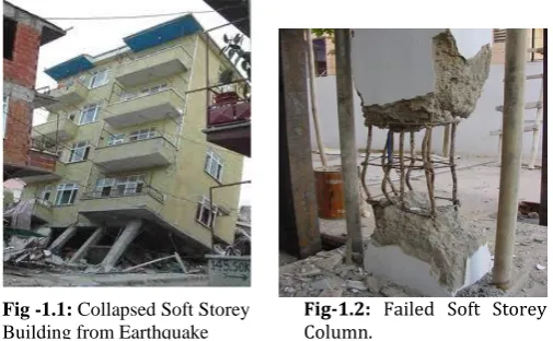
is less than the stories above or below. Therefore buildingswith soft storey act as an Inverted Pendulum i.e. it oscillates back and forth, this back and forth movement produces high stresses in columns and if columns are incapable of taking these stresses or do not posses enough ductility, they could get huge damaged and which can also collapse of the building. This is also known as inverted pendulum action. Soft stories go under larger lateral loads during earthquakes. These lateral forces are not easy to distribute along the height of structure. This causes the lateral forces to act on the storeys which have large displacement. The lateral force distribution along the height of a building is directly related to mass and stiffness of each storey.
Fig-1.2: Failed Soft Storey Column.
The presence of infill walls in the upper storey of the soft storey buildings increases the stiffness of the building globally, as seen in a typical infilled framed building. Due to the increase of global stiffness, the base shear demand on the building increases. In the case of typical infilled frame building, the increased base shear is shared by both frames and infill walls in the entire storey. In soft storey buildings, where the infill walls are not present in the ground storey (no truss action), the increased base shear is resisted entirely by the ground storey columns, without any load sharing possible by adjoining infill walls. The increased shear forces in the ground storey columns will induce increased bending moments and there by higher curvatures, causing relatively larger drifts at the first floor level. The large lateral deflections further enhance the bending moments due to the P-Δ effect. Plastic hinges are developed at the top and bottom ends of the ground storey columns. The upper storeys would remain undamaged and move almost like a rigid body. The damage is mostly concentrated in the ground storey columns, and this is termed as typical ‘soft-storey collapse’. This is also called a ‘storey-mechanism’ or ‘column mechanism’ in the ground storey.
1.2 Objective of Work
The objectives of the project are to study the results of: - 1) Base Shear for all the models to compare and find the best possible model.
2) Displacement for all the models on each floor of the selected columns.
3) Axial Force for all the models for all the selected columns.
4) Bending Moment-Y for all the models on each floor for all the selected columns.
5) Bending Moment-Z for all the models on each floor for all the selected columns.
6) Floor wise Displacement, Axial Force, Bending moment-Y and Bending Moment-Z.
Using these results the behavior of soft storey building is studied and the best wall thickness or combination of wall thickness is found.
1.3 Methodology
• A RC-Frame, medium rise G+10 building with first soft storey and a suitable building plan were finalized.
• Modelling of selected building was done using STAAD Pro V8 software. The loading and specifications of the building are done with regard to IS 1893(Part 1)-2002, IS 1893-1984, IS 456.
• To consider the stiffness of masonry infill in STAAD, struts are provided within the frame of the building. Equivalent width of struts was calculated using Paulay and Priestley’s formula. Struts are provided only to behave as a compression member, struts in tension were not provided. • Suitable cross-section for the columns of the building is designed using STAAD Pro.
• Equivalent static analysis for Zone-III as per IS 1893:2002 is performed for 9 different columns.
• Earthquake in X & Z directions are considered seperately. Only positive direction earthquake are considered and the struts are provided parallel to the positive direction of earthquake.
• Graphs to determine the most sever load case for the selected 9 columns were made. The different load cases selected were-
In X-direction strut models i. 1.2(DL+LL+EQX) ii. 1.5(DL+EQX) iii. 0.9DL+1.5EQX iv. 1.5(DL+LL) v. 1.2(DL+LL) vi. 1.5DL
In Z-direction strut models i. 1.2(DL+LL+EQZ) ii. 1.5(DL+EQZ) iii. 0.9DL+1.5EQZ iv. 1.5(DL+LL) v. 1.2(DL+LL) vi. 1.5DL
From these graphs the maximum displacement, axial force, bending moment-Y, bending moment-Z were found for the most sever load case.
© 2015, IRJET.NET- All Rights Reserved
Page 1764
• Base Shear, Displacement, Axial Force, BendingMoment-Y, Bending Moment-Z & Floor wise distribution of all the above parameters are also analysed with regard to STAAD.
1.3.1 Modelling of Equivalent struts
The strength and the stiffness of infill walls in a RC-Frame building should be considered. Infill walls act as a compressive member within a frame. Non-integrated infill walls act as a diagonal strut when subjected to lateral loads. Therefore an infill wall can be modeled as a diagonal strut in compression only.
In this project the modeling of diagonal struts is performed using Paulay and Priestley paper published in 1992. In their paper they stated that the equivalent width of a diagonal strut can be taken as 1/4 th of the diagonal length of an infill wall.
Fig -1.3: Dimensions of walls
The different widths of struts calculated are: - Table-1.1: Equivalent Width of struts
Length x Height
Diagonal Length(m)
Equivalent width of Strut(m)
3x3m 4.24 1.06
4x3m 5 1.25
7x3m 7.62 1.9
While modelling a single strut, triangular struts are provided at both ends of the beam column joints and the equivalent width provided between the two triangular struts.
1.3.2 Specification
Table-1.2: Specifications
Sr. No.
Parameters Dimensions/Type
1 Plan dimensions 14 m x 14 m
2 Number of stories G+10
3 Total height of building 33.00 m 4 Height of each storey 3m
5 Size of beams 300 X 400 mm
6 Size of columns 450 X 600 mm
7 Thickness of slab 120 mm
8 Thickness of walls 250mm,150mm
&250-150mm
9. Frame Type OMRF
9 Seismic zone III
10 Soil condition Medium
11 Importance 1
12 Response Reduction 3
13 Damping Ratio of structure
0.05
14 Live load a) On floor
b) On roof
2.5 KN/m2
none
15 Floor Finishing 35mm thick
16 Material M30 Grade
Concrete
17 Unit weights a) Concrete = 25
KN/Cum b) Masonry =20 KN/Cum
1.3.3 Plan
Fig -1.4: Plan Top View
© 2015, IRJET.NET- All Rights Reserved
Page 1765
1.3.4 Structural Models
Model 1:-Bare Frame with 250mm Outer wall & 150mm Inner wall thickness.
Model 2:-250mm Outer wall & 150mm Inner wall thickness with Struts in X-Direction.
Model 3:-250mm Outer wall & 150mm Inner wall thickness with Struts in Z-Direction.
Model 4:-Bare Frame with Uniform 150mm wall thickness. Model 5:-Uniform 150mm wall thickness with Struts in
X-Direction.
Model 6:-Uniform 150mm wall thickness with Struts in Z-Direction.
Model 7:-Bare Frame with Uniform 250mm wall thickness. Model 8:-Uniform 250mm wall thickness with Struts in
X-Direction.
Model 9:-Uniform 150mm wall thickness with Struts in Z-Direction.
1.3.5 Images of STAAD Models
Front View
Fig-1.6: Bare frame model
Front View 3D View
Fig-1.7: Struts in X-Direction model
Side View 3D View
Fig-1.8: Struts in Z-Direction model
2. Analysis and Results
2.1 Base Shear
For Earthquake in X-direction
Table-1: Base shear for earthquake in X-direction
Models
Base Shear (KN)
Bare Frame 250-150 mm 1144.732
250-150mm with Struts in X-Direction 1489.21
Bare Frame Full 150mm 1004.601
Full 150mm with Struts in X-Direction 1306.909
Bare Frame Full 250mm 1244.826
Full 250mm with Struts in X-Direction 1619.425
Figure-2.1: Base shear for earthquake in X-direction
For Earthquake in Z-direction
Table-2: Base shear for earthquake in Z-direction
Models Base Shear (KN)
Bare Frame 250-150mm 1144.732
250-150mm with Struts in Z-Direction 1519.336
Bare Frame Full 150mm 1004.601
Full 150mm with Struts in Z-Direction 1328.515
Bare Frame Full 250mm 1244.826
Full 250mm with Struts in Z-Direction 1655.433
© 2015, IRJET.NET- All Rights Reserved
Page 1766
Figure-2.2: Base shear for earthquake in Z-direction2.2 Displacement
Maximum Displacement for Column
For Earthquake in X-Direction
Table-3: Displacement by column for earthquake in X-direction Co
Fig-2.3: Displacement by column for earthquake in X-direction
For Earthquake in Z-Direction
Table-4: Displacement by column for earthquake in Z-direction
Fig-2.4: Displacement by column for earthquake in Z-direction
Maximum Displacement by Model
For Earthquake in X-Direction
Table5: Displacement by model for earthquake in X-direction
Models with struts in X-direction
Maximum Displacement
(mm)
Bare Frame 250-150mm 69.146
250-150 mm with struts in X-Direction 17.645
Bare Frame Full 150 mm 61.031
Full 150mm with Struts in X-Direction 18.776
Bare Frame Full 250 mm 74.939
© 2015, IRJET.NET- All Rights Reserved
Page 1767
Fig-2.5: Displacement by model for earthquake in X-directionFor Earthquake in Z-Direction
Table-6: Displacement by model for earthquake in Z-direction
Models with struts in Z-direction
Maximum Displacement
(mm)
Bare Frame 250-150mm 64.58
250-150 mm with struts in Z-Direction 14.089
Bare Frame Full 150 mm 57
Full 150mm with Struts in Z-Direction 14.018
Bare Frame Full 250 mm 70.006
Full 250mm with Struts in Z-Direction 13.973
Fig-2.6: Displacement by model for earthquake in Z-direction
Maximum Floor wise Displacement Graphs
For Earthquake in X-Direction
Table-7: Floor wise Displacement for earthquake in X-direction Heig
Fig-2.7: Floor wise displacement for earthquake in X-direction
For Earthquake in Z-Direction
Table-8: Floor wise Displacement for earthquake in Z-direction
© 2015, IRJET.NET- All Rights Reserved
Page 1768
Fig-2.8: Floor wise displacement for earthquake in Z-direction2.3 Maximum Axial Force
Maximum Axial Force by Column
For Earthquake in X-Direction
Table-9: Axial force by column for earthquake in X-direction Co
Fig-2.9: Axial force by column for earthquake in X-direction
For Earthquake in Z-Direction
Table-10: Axial force by column for earthquake in Z-direction Co
Fig-2.10: Axial force by column for earthquake in Z-direction
Maximum Axial Force by Model
For Earthquake in X-Direction
Table-11: Axial force by model for earthquake in X-direction
Models with struts in X-direction
Maximum Axial Fore (KN)
Bare Frame 250-150mm 4115.813
250-150 mm with struts in X-Direction 3671.029
Bare Frame Full 150 mm 3691.237
Full 150mm with Struts in X-Direction 3366
Bare Frame Full 250 mm 4427.938
© 2015, IRJET.NET- All Rights Reserved
Page 1769
Fig-2.11: Axial force by model for earthquake in X-directionFor Earthquake in Z-Direction
Table-12: Axial force by model for earthquake in Z-direction
Models with struts in Z-direction
Maximum Axial Fore
(KN)
Bare Frame 250-150mm 4115.813
250-150 mm with struts in Z-Direction 3670.326
Bare Frame Full 150 mm 3691.237
Full 150mm with Struts in Z-Direction 3292.141
Bare Frame Full 250 mm 4427.938
Full 250mm with Struts in Z-Direction 3886.215
Fig-2.12: Axial force by model for earthquake in Z-direction
Maximum Floor wise Axial Force
For Earthquake in X-Direction
Table-13: Floor wise axial force for earthquake in X-direction He
Fig-2.13: Floor wise axial force for earthquake in X-direction
For Earthquake in Z-Direction
Table-14: Floor wise axial force for earthquake in Z-direction
© 2015, IRJET.NET- All Rights Reserved
Page 1770
Fig-2.14: Floor wise axial force for earthquake in Z-direction2.4 Bending Moment-Y
Maximum Bending Moment-Y by Column
For Earthquake in X-Direction
Table-15: Bending moment-Y by column for earthquake in
X-For Earthquake in Z-Direction
Z-© 2015, IRJET.NET- All Rights Reserved
Page 1771
Maximum Bending Moment-Y by ModelFor Earthquake in X-Direction
Table-17: Bending moment-Y by model for earthquake in X-direction
Models with struts in X-direction
Maximum Bending Moment-Y (KN-m)
Bare Frame 250-150mm 127.799
250-150 mm with struts in X-Direction 110.505
Bare Frame Full 150 mm 112.164
Full 150mm with Struts in X-Direction 94.164
Bare Frame Full 250 mm 138.966
Full 250mm with Struts in X-Direction 110.85
Fig-2.17: Bending moment-Y by model for earthquake in X-direction
For Earthquake in Z-Direction
Table-18: Bending moment-Y by model for earthquake in Z-direction
Models with struts in Z-direction
Maximum Bending Moment-Y (KN-m)
Bare Frame 250-150mm 195.389
250-150 mm with struts in Z-Direction 200.195
Bare Frame Full 150 mm 172.24
Full 150mm with Struts in Z-Direction 174.563
Bare Frame Full 250 mm 213.25
Full 250mm with Struts in Z-Direction 212.768
Fig-2.18: Bending moment-Y by model for earthquake in Z-direction
Maximum Floor wise Bending Moment-Y Graphs
For Earthquake in X-Direction
Table-19: Floor wise bending moment-Y by model for earthquake in X-direction
Flo or
H ei gh t
Bare Fram e 250-150 mm
250-150 mm with strut s In X-Direc tion
Bare Fra me Full 150 mm
Full 150 mm with Stru ts In X-Dire ctio n
Bare Fram e Full 250 mm
Full 250m m with Strut s In X-Direc tion GF 0 127.7 80.96 112 68.5 138.9 81.20 1F 3 113.1 110.5 94.8 94.1 116.7 110.5 2F 6 100.4 97.17 86.9 83.6 107.7 97.65 3F 9 102.6 99.25 86.6 85.4 103.6 99.81 4F 12 103.1 99.53 87.2 85.9 104.2 100.2 5F 15 103.7 100.2 88.0 86.6 105.0 100.9 6F 18 104.2 100.6 88.5 87.1 105.6 101.4 7F 21 105.1 101.3 89.1 87.7 106.5 102.2 8F 24 104.5 100.8 89.1 87.5 106 101.8 9F 27 111.7 107.8 92.6 91.2 113 108.6 10
© 2015, IRJET.NET- All Rights Reserved
Page 1772
Fig-2.19: Floor wise bending moment-Y by model for earthquakein X-direction
For Earthquake in Z-Direction
Table-20: Floor wise bending moment-Y by model for earthquake in Z-direction
Fl
Fig-2.20: Floor wise bending moment-Y by model for earthquake in X-direction
2.5 Maximum Bending Moment-Z
Max Bending Moment-Z by Column
For Earthquake in X-Direction
Table-21: Bending moment-Z by column for earthquake in
X-For Earthquake in Z-Direction
Z-© 2015, IRJET.NET- All Rights Reserved
Page 1773
C5 173.5 0.184 152.3 0.113 188.7 0.18C6 142.9 0.56 125.5 0.871 155.4 0.62 C7 156.0 27.67 136.9 27 169.6 32.6 C8 173.6 0.387 152.4 0.213 188.8 0.39 C9 155.7 31.89 136.7 27.241 169.3 34.2
Fig-2.22: Bending moment-Z by column for earthquake in Z-direction
Max Bending Moment-Z by Model
For Earthquake in X-Direction
Table-23: Bending moment-Z by model for earthquake in X-direction
Models with struts in X-direction
Maximum Bending Moment-Z (KN-m)
Bare Frame 250-150mm 260.547
250-150 mm with struts in X-Direction 206.979
Bare Frame Full 150 mm 228.691
Full 150mm with Struts in X-Direction 187.873
Bare Frame Full 250 mm 283.302
Full 250mm with Struts in X-Direction 219.612
Fig-2.23: Bending moment-Z by model for earthquake in X-direction
For Earthquake in Z-Direction
Table-24: Bending moment-Z by model for earthquake in Z-direction
Models with struts in Z-direction
Maximum Bending Moment-Z
(KN-m)
Bare Frame 250-150mm 173.698
250-150 mm with struts in Z-Direction 32.385
Bare Frame Full 150 mm 152.46
Full 150mm with Struts in Z-Direction 27.241
Bare Frame Full 250 mm 188.868
Full 250mm with Struts in Z-Direction 34.284
Fig-2.24: Bending moment-Z by model for earthquake in Z-direction
Floor wise Max Bending Moment-Z Graphs
For Earthquake in X-Direction
Table-25: Floor wise bending moment-Z for earthquake in X-direction
Fl oo r
He ig ht
Bare Fram e 250-150m m
250-150 mm with struts In X-Direc tion
Bare Fram e Full 150 mm
Full 150m m with Strut s In X-Direc tion
Bare Fram e Full 250 mm
Full 250m m with Strut s In X-Direc tion GF 0 127.7 80.96 112.1 68.56 138.9 81.20 1F 3 113.0 110.5 94.87 94.16 116.7 110.8 2F 6 100.4 97.17 86.98 83.63 107.7 97.65 3F 9 102.6 99.25 86.62 85.49 103.6 99.81 4F 12 103.2 99.53 87.22 85.96 104.2 100.2 5F 15 103.7 100.2 88.00 86.65 105.0 100.9 6F 18 104.2 100.6 88.53 87.13 105.6 101.4 7F 21 105.1 101.3 89.17 87.73 106.5 102.2 8F 24 104.5 100.8 89.04 87.58 106.0 101.8 9F 27 111.7 107.8 92.63 91.26 113.0 108.6 10
F
© 2015, IRJET.NET- All Rights Reserved
Page 1774
Fig-2.25: Floor wise bending moment-Z for earthquake inX-direction
For Earthquake in Z-Direction
Table-26: Floor wise bending moment-Z for earthquake in Z-direction
Fl oo r
H ei gh t
Bare Fram e 250-150m m
250-150 mm with strut s In Z-Direc tion
Bare Fram e Full 150 mm
Full 150 mm with Stru ts In Z-Dire ctio n
Bare Fram e Full 250 mm
Full 250m m with Strut s In Z-Direc tion
GF 0 173.6 20.72 152.4 20.3 188.8 24.63 1F 3 152.3 28.47 133.7 27 165.6 32.61 2F 6 139.5 26.26 122.5 21.7 151.6 27.78 3F 9 132.2 27.43 116.0 23.0 143.4 29.34 4F 12 130.7 28.18 114.8 23.9 142.1 30.40 5F 15 127.3 28.88 111.9 24.8 138.4 31.35 6F 18 120. 29.42 105.7 25.4 130.4 32.08 7F 21 108.7 29.98 95.84 25.9 117.8 32.74 8F 24 92.85 29.94 82.19 26.3 100.4 32.85 9F 27 68.14 31.89 60.79 26.5 73.38 34.28 10
F
30 46.78 32.38 42.91 27.2 49.52 32.30
Fig-2.26: Floor wise bending moment-Z for earthquake in Z-direction
2.6 Percentage variation of different Models
Percentage variation of Base Shear
For Earthquake in X-Direction
Table-27: Percentage variation of base shear for earthquake in X-direction
Models
% variation w.r.t Bare Frame Full
150mm
Bare Frame 250-150 mm 13.95
250-150mm with Struts in X-Direction 48.240
Bare Frame Full 150mm 1.000
Full 150mm with Struts in X-Direction 30.1
Bare Frame Full 250mm 23.9
Full 250mm with Struts in X-Direction 61.2
Fig-2.27: Percentage variation of base shear for earthquake in X-direction
For Earthquake in Z-Direction
Table-28: Percentage variation of base shear for earthquake in Z-direction
Models
% variation w.r.t Bare Frame Full
150mm
Bare Frame 250-150mm 13.95
250-150mm with Struts in Z-Direction 51.45
Bare Frame Full 150mm 1.000
Full 150mm with Struts in Z-Direction 32.240
Bare Frame Full 250mm 23.9
© 2015, IRJET.NET- All Rights Reserved
Page 1775
Fig-2.28: Percentage variation of base shear for earthquake inZ-direction
Percentage variation of Displacement
For Earthquake in X-Direction
Table-29: Percentage variation of displacement for earthquake in X-direction
Models with struts in X-direction
% variation w.r.t 250-150 mm with
struts in X-Direction
Bare Frame 250-150mm 391.8
250-150 mm with struts in X-Direction 1
Bare Frame Full 150 mm 345.8
Full 150mm with Struts in X-Direction 6.41
Bare Frame Full 250 mm 424.7
Full 250mm with Struts in X-Direction 2.63
Fig-2.29: Percentage variation of displacement for earthquake in X-direction
For Earthquake in Z-Direction
Table-30: Percentage variation of displacement for earthquake in Z-direction
Models with struts in Z-direction
% variation w.r.t Full 250mm with
Struts in Z-Direction
Bare Frame 250-150mm 462.2
250-150 mm with struts in Z-Direction 0.83
Bare Frame Full 150 mm 407.9
Full 150mm with Struts in Z-Direction 0.32
Bare Frame Full 250 mm 501
Full 250mm with Struts in Z-Direction 1
Fig-2.30: Percentage variation of displacement for earthquake in Z-direction
Percentage variation of Axial Force
For Earthquake in X-Direction
Table-31: Percentage variation of axial force for earthquake in X-direction
Models with struts in X-direction
% variation w.r.t Full 150mm with
Struts in X-Direction
Bare Frame 250-150mm 22.3
250-150 mm with struts in X-Direction 9.06
Bare Frame Full 150 mm 9.66
Full 150mm with Struts in X-Direction 1
Bare Frame Full 250 mm 31.55
© 2015, IRJET.NET- All Rights Reserved
Page 1776
Fig-2.31: Percentage variation of axial force for earthquake inX-direction
For Earthquake in Z-Direction
Table-32: Percentage variation of axial force for earthquake in Z-direction
Models with struts in Z-direction
% variation w.r.t Full 150mm with
Struts in Z-Direction
Bare Frame 250-150mm 25.02
250-150 mm with struts in Z-Direction 11.49
Bare Frame Full 150 mm 12.12
Full 150mm with Struts in Z-Direction 1
Bare Frame Full 250 mm 34.5
Full 250mm with Struts in Z-Direction 18.05
Fig-2.32: Percentage variation of axial force for earthquake in Z-direction
Percentage variation of Bending Moment-Y
For Earthquake in X-Direction
Table-33: Percentage variation of bending moment-Y for earthquake in X-direction
Models with struts in X-direction
% variation w.r.t Full 150mm with
Struts in X-Direction
Bare Frame 250-150mm 35.72
250-150 mm with struts in X-Direction 17.35
Bare Frame Full 150 mm 19.12
Full 150mm with Struts in X-Direction 1
Bare Frame Full 250 mm 47.58
Full 250mm with Struts in X-Direction 17.72
Fig-2.33: Percentage variation of bending moment-Y for earthquake in X-direction
For Earthquake in Z-Direction
Table-34: Percentage variation of bending moment-Y for earthquake in Z-direction
Models with struts in Z-direction
% variation w.r.t Bare Frame Full
150 mm
Bare Frame 250-150mm 13.44
250-150 mm with struts in Z-Direction 16.23
Bare Frame Full 150 mm 1
Full 150mm with Struts in Z-Direction 1.35
Bare Frame Full 250 mm 23.81
© 2015, IRJET.NET- All Rights Reserved
Page 1777
Fig-2.34: Percentage variation of bending moment-Y forearthquake in Z-direction
Percentage variation of Bending Moment-Z
For Earthquake in X-Direction
Table-35: Percentage variation of bending moment-Z for earthquake in X-direction
Models with struts in X-direction
% variation w.r.t Full 150mm with
Struts in X-Direction
Bare Frame 250-150mm 38.68
250-150 mm with struts in X-Direction 10.17
Bare Frame Full 150 mm 21.72
Full 150mm with Struts in X-Direction 1
Bare Frame Full 250 mm 50.79
Full 250mm with Struts in X-Direction 16.89
Fig-2.35: Percentage variation of bending moment-Z for earthquake in X-direction
For Earthquake in Z-Direction
Table-36: Percentage variation of bending moment-Z for earthquake in Z-direction
Models with struts in Z-direction
% variation w.r.t Full 150mm with
Struts in Z-Direction
Bare Frame 250-150mm 637.6
250-150 mm with struts in Z-Direction 18.88
Bare Frame Full 150 mm 559.6
Full 150mm with Struts in Z-Direction 1
Bare Frame Full 250 mm 693.3
Full 250mm with Struts in Z-Direction 25.85
Fig-2.36: Percentage variation of bending moment-Z for earthquake in Z-direction
3. CONCLUSIONS
3.1
Base Shear
For earthquake in X-direction: - All the Bare Frames models have less base shear than their respective models with struts in X-direction by a factor of 1.3 For earthquake in Z-direction: - All the Bare Frames
models have less base shear than their respective models with struts in Z-direction by a factor of 1.33
3.2
Displacement
For earthquake in X-direction
© 2015, IRJET.NET- All Rights Reserved
Page 1778
ii. The uniform 150mm walls model with strut inX-direction shows decreased displacement as compared to its Bare Frame model by a factor of
3.25
iii. The uniform 250mm walls model with strut in X-direction shows decreased displacement as compared to its Bare Frame model by a factor of
4.14
For earthquake in Z-direction
i. The 250mm outer and 150mm inner walls model with strut in Z-direction shows decreased displacement as compared to its Bare Frame model by a factor of 4.58
ii. The uniform 150mm walls model with strut in Z-direction shows decreased displacement as compared to its Bare Frame model by a factor of 4.1
iii. The uniform 250mm walls model with strut in Z-direction shows decreased displacement as compared to its Bare Frame model by a factor of
5.01
3.3
Axial Force
The axial force comparison between bare frame models and their respective with strut models shows that the axial forces are almost same between them.
3.4
Bending moment-Y
For earthquake in X-direction
i. The 250mm outer and 150mm inner walls model with strut in X-direction shows decreased bending moment-Y as compared to its Bare Frame model by a factor of 1.16
ii. The uniform 150mm walls model with strut in X-direction shows decreased bending moment-Y as compared to its Bare Frame model by a factor of
1.19
iii. The uniform 250mm walls model with strut in X-direction shows decreased bending moment-Y as compared to its Bare Frame model by a factor of
1.25
For earthquake in Z-direction
The bending moment-Y is same for Models with Struts in Z-direction and their respective bare frame models.
3.5
Bending moment-Z
For earthquake in X-direction
i. The 250mm outer and 150mm inner walls model with strut in X-direction shows decreased bending moment-Z as compared to its Bare Frame model by a factor of 1.26
ii. The uniform 150mm walls model with strut in X-direction shows decreased bending moment-Z as compared to its Bare Frame model by a factor of
1.22
iii. The uniform 250mm walls model with strut in X-direction shows decreased bending moment-Z as compared to its Bare Frame model by a factor of
1.29
For earthquake in Z-direction
i. The 250mm outer and 150mm inner walls model with strut in Z-direction shows decreased bending moment-Z as compared to its Bare Frame model by a factor of 5.36
ii. The uniform 150mm walls model with strut in Z-direction shows decreased bending moment-Z as compared to its Bare Frame model by a factor of
5.59
iii. The uniform 250mm walls model with strut in Z-direction shows decreased bending moment-Z as compared to its Bare Frame model by a factor of
5.51
Observing all the conclusions the Uniform 150mm wall thickness with struts model and its bare frame model are the best models according to the parameters studied in this project.
REFERENCES
[1] Suchita Hirde and Ganga Tepugade, “Seismic Performance of Multistorey Building with Soft Storey at Different Level with RC Shear Wall”, International Journal of Current Engineering and Technology, Vol.4, No.3, June 2014.
[2] Hiten L. Kheni, and Anuj K. Chandiwala, “Seismic Response of RC Building with Soft Stories”, International Journal of Engineering Trends and Technology, Vol-10, Apr 2014.
[3] Rakshith Gowda and Bhavani Shankar, “Seismic Analysis Comparison of Regular and Vertically Irregular RC Building with Soft Storey at Different Level”, International Journal of Emerging Technologies and Engineering (IJETE), Volume 1 Issue 6, July 2014.
© 2015, IRJET.NET- All Rights Reserved
Page 1779
[5] S. B. Smith and C. Carter, “A Method of Analysis forInfilled Frames”, Proceedings of Institution of Civil Engineers, Vol-44, Page no. 31-48, 1969.
[6] IS 1893(Part I): (2002), “Criteria for Earthquake Resistant Design of Structures.” Bureau of Indian Standards, New Delhi, 2002.