Optimized Routing for Cooperative Wireless Sensor Networks
1 A.Abhisarika, 2 B.Rajanna, 3 Dr.P.Chandrashekar1
M.Tech Student, Department of ECE, Vaagdevi College of Engineering, Warangal District, Telangana, India.
2Associate Professor,Research from Vel-Tech RR & SR Technical university, chennai,
Department of ECE,Vaagdevi College of Engineering, Warangal District, Telangana, India 3Head of Department of EEE, Vel-Tech RR & SR Technical university, chennai.
Abstract:
We consider the heterogeneity of systems and propose a reasonable helpful steering technique, to keep away from uncalled for development just on specific systems. We present one or a couple of shared hubs that can utilize various channels to hand-off information bundles. Accepting that sinks and shared hubs can speak with any WSNs here, various WSNs can utilize agreeable directing with each other since shared hubs enable sensor hubs to forward information from another WSN as the capacity of exchange focuses among particular WSN planes. While getting a bundle, a mutual hub chooses the course to send the parcel, as indicated by proposed course choice techniques. This collaboration drags out the lifetime of each system similarly as possible.
Keywords: Sensor Network, Cooperative
Routing, Fairness, Heterogeneous Environment, Load Balancing.
I.INTRODUCTION
Wireless sensor networks (WSNs) are made out of small battery-controlled sensor hubs that have
restricted capacity and radio
capabilities.Therefore, for WSNs to stay operational for quite a while, much consideration must be paid to vitality utilization in the hubs. In a run of the mill WSN, sensor
hubs obtain and send information to a preparing focus called the sink. Since all information are sent to a sink, hubs around the sink have a tendency to transmit numerous a greater number of bundles than the others. For this situation, the vitality of such hubs will debilitate sooner than that of different hubs, causing a "vitality gap" to show up around the sink. No more information can be conveyed to the sink after the opening shows up. Thusly, the vitality staying in whatever is left of the system is squandered, and the system lifetime is shorter than it could. In a few applications, a WSN may contain a few thousand sensor hubs inside an expanded
territory (e.g., farming and ecological
observing). In these cases, the width of the WSN might be a few kilometers. To empower systems to be versatile, a WSN is normally subdivided into bunches and the information gathered by group heads are sent to a sink. Bunching additionally bolsters information accumulation. This is a strategy by which
information from various sensors are
consolidated to wipe out repetitive data and transmission, subsequently diminishing vitality utilization. From another perspective, WSNs can be arranged into two sorts, in particular
homogeneous and heterogeneous sensor
systems. In a homogeneous WSN, all hubs have similar capacities.
few "top of the line" sensor hubs, with a more extensive scope of radio correspondence capacities or potentially a bigger battery contrasted and the "typical" hubs. A bunching technique to accomplish compelling utilization of these top of the line hubs has been proposed. Be that as it may, a bunching strategy alone isn't adequate to draw out the system lifetime for a heterogeneous WSN, and a grouping and multi-bounce cross breed directing technique has accordingly been proposed. As of late, numerous WSNs have been developed inside the same geographic range. For such cases, analysts have been examining collaboration between the WSNs. Some directing conventions for numerous WSNs have been proposed. In this paper, we propose a directing strategy for helpful sending to delay organize lifetime by diminishing the heap on hubs around sinks in a different WSN condition. By lessening the heap around a sink, we intend to conquer the issue of a few hubs getting to be "bottlenecks". Our technique chooses how much different WSNs with different sink locations can help such “heavy-load” situations.
II. RELATED WORK
In recent years, the quantity of utilizations of WSNs has been expanding, with various WSNs drawing in much consideration. For such conditions, a few conventions have been proposed, as takes after, The Virtual Sensor Network (VSN) is a developing idea for supporting multipurpose, shared and asset productive WSNs by empowering, for instance, dynamic varieties to the subsets of sensors and clients. A VSN is shaped as a sensible system of
agreeable hubs. For situations where
applications cover geologically, transmitting information for applications among an assortment of gadgets empowers the hubs to lessen excess ways. Hubs are grouped into a proper VSN in light of the wonders they are
following (e.g., holder following or
consumption rate observing). It is normal that VSNs will give conventions to the development strategies, upkeep and use of subsets of sensors, giving an approach to convey effectively between middle of the road hubs or different VSNs. Poorter et al, propose to build an overlay organize for various WSNs. In any case, this convention has the issue that distinctions in working strategies and radio interchanges are not considered. Steffan et al, concentrate on a general idea for the creation and support of system wide hub subsets and portray an adaptable and secluded engineering that meets the prerequisites of multipurpose WSNs. Be that as it may, the production of these subsets isn't
extremely adaptable. Most applications
III. PROPOSED METHOD
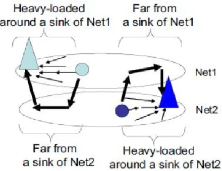
A. ConceptIt is assumed that there are n WSNs in the same area. These WSNs have different applications. In addition, their start and finish times may differ, depending on each network’s requirements. As shown in Fig.1, the locations of the sinks in multiple WSNs are separated. Some nodes around a sink in
Fig.1. Heavy-load node around a sink
one WSN may therefore be far from a sink in another WSN.We focus on this fact in the proposed method, whereby a node that is far from a sink in its own network, but near a sink in another network, can forward a packet from a node in another WSN to the corresponding sink. In this paper, we call the former network the home network and the latter network the visitor network. The method achieves load balancing between a heavy-load node in a home network and a light-load node in a visitor network. As a result, the lifetime of both networks can be extended. Specifically, eachnetwork constructs a path along which a node can’t forward a packet from a node in another WSN in advance. It is based on the well-known Ad hoc On-Demand Distance Vector (AODV) protocol), making it
easy to implement. In addition, some nodes construct routes to the sinks of visitor networks.
B. Node Function
As described above, the proposed method enables a node that is far from a sink in its home network, but near a sink in a visitor network, and can forward a packet from a node in the visitor network. Each node has a routing table that includes not only an entry for a sink in its home network but also an entry for a sink in the visitor network. When a node overhears a data packet from its visitor network, it decides whether to receive and forward it or to ignore it. This procedure is explained later in more detail.
C. Routing Table Creation
This subsection explains how to create the routing table. Initially, each node sends an AODV-based route request packet to create an entry in its routing table for a sink in its home network. After this creation process, each node broadcasts an additional route request packet named B-REQ to the sinks of all visitor networks. (Nodes on the path from the node to the sink will create an entry in their routing table to the sink.) In addition, as a metric to decide the next hop, min Energy is also notified. This refers to the minimum residual energy of nodes along the path to the sink.
D. Cooperative Routing Method
value of minimum energy along the paths every networks and select the path for the maximum value of this energy. Fig.2 demonstrates how the proposed method works. After node P has the created path in its home network (Sink1), it broadcasts a B-REQ to the visitor networks Net2 and Net3. When node Q and node R receive this B-REQ, they write their network ID in the header of the B-REQ and transmit it to their sink. After this procedure, the routes from node P to the sink via Net2 and Net3 are created, as shown in Tables I and II, respectively. When node P receives a data packet for Sink1, it selects a suitable route from the entries in its routing table as shown in Table I. In this case, node P selects node R, which has the maximum value for min Energy, as the next-hop node. As we described below, the proposed method tries to extend the lifetime of each network by cooperative forwarding. However, it may result in a case where a network shortens its lifetime by the burden of forwarding for visitor networks. To avoid such a situation, in the proposed method, a node which has less residual energy does not relay packets from visitor networks. Specifically, we define a value of cooperation threshold in each network as a metric to decide whether to forward packets from visitor networks or not. For this metric, each sink broadcasts the minimum value of residual energy among all the nodes in its home network to the nodes in its home network. When a node acquires the value, it compares with its own residual energy. If its own residual energy is smaller, it refuses to forward packets from visitor networks and applies itself to relay packets in its home network.
IV. PERFORMANCE EVALUATION
A. Simulation Environment
We evaluated the performance of the proposed method with the network simulator QualNet 7.1.
We observed the receiving rate, which is the rate of sensor nodes that send data packets to their sinks successfully. Therefore, we counted a node that cannot communicate with its sink as a dead node, in spite of its remaining battery. The maximum value of receiving rate is 1. In this
simulation model, we set the node
configurations using datasheet and information provided by MEMSIC. We simulated four WSNs, WSN 1, WSN 2, WSN 3 andWSN4 as follows. Each WSN had 49 nodes based on a random topology. The sensing field was a 490 m ×490 m square.
Fig.2. Receiving rate on WSN 1
entries and discovered new routes at intervals of 720 minutes. We evaluated two proposed method, Pool-based and Life based. For comparison, we simulated an environment where four WSNs were operated independently without any cooperation. In addition, Energy-based method was also evaluated as a conventional method. It just focuses on prolonging total lifetime but ignores the fairness among WSNs.
B. Simulation Results Scenario 1
: Heterogeneous Battery Capacity: As a basic evaluation for heterogeneity, sensor nodes have different battery capacity by a WSN. WSN 1 has the largest capacity and WSN 4 has the lowest. We set the battery capacity of a node in WSN 1 to 1, and the capacity ratio is represented as; WSN1: WSN2: WSN3: WSN4 = 1: 0.75: 0.625: 0.5. Note that each node does NOT need to know the initial capacity of nodes in other WSNs. All each node has to know is its own initial capacity for operating the proposed method properly. Figs 3-6 show the receiving rate as a function of elapsed time for each WSN. They are averaged over 10 trials. We can see that Pool-based and Life-based cooperation extend the lifetime of WSN1 in Fig.3. Especially, Pool-based achieved dramatic improvement. On the other hand, Energy-based cooperation degraded the lifetime of WSN1, since WSN1 has larger battery capacity than any other WSNs. On Energy based, a shared node always selects the route that has the maximum residual energy. Therefore, in this scenario, the route via WSN1 forwarded a lot of packets from other WSNs and WSN1 consumed much more energy than any other WSNs, As a result, the lifetime of WSN1 was shortened. To the contrary, on Pool-based, the route via each WSN forwarded the almost same amount of data packets. Hence, WSN1 was also able to improve its lifetime. On Life-based, since a
shared node compares the estimated lifetime of the routes, the heavy-loaded nodes tend to be avoided even if they belongs to WSN1.
Fig.4 Receiving rate on WSN 2
Fig.6. Receiving rate on WSN 4
In Figs. 4, 5 and 6, we can see both the proposed method and conventional method improved network lifetime. For evaluation, we define the α−life time as the time when the receiving rate has fallen below α on a WSN. We also define life improving ratio, which is represented by α – life time
Fig.7. Average of life improving ratio in 4 WSNs (scenario 1)
Fig.8. Total amount of extended lifetime in 4 WSNs (scenario 1)
on the method divided by α − lifetime in no cooperation scenario. Fig.7 shows the average life improving ratio in 4 WSNs for each method as a function of α. All methods extended the network lifetime by cooperative forwarding’s. In most of other range than α close to 1,
specifically, Life-based and Pool-based
achieved greater benefits than Energy-based. Since the networks have different battery capacities, the lifetime of those without cooperation are also different. Even if the total amount of extended lifetime is equal, the life improving ratio may take a larger value with
smaller battery capacity. Hence, for
successfully plays a role of broker for cooperation.
Scenario2:
Heterogeneous Data Transmission: We
evaluated the 4 WSNs that send data packets in different timing. In this scenario, WSN1, WSN2, WSN3 and WSN4 send a data packet every 10 minutes, every 7.5 minutes,
Fig.9. Variance of life improving ratio in 4 WSNs (scenario 1)
Fig.10. Average of lifetime improving ratio in 4 WSNs (scenario 3)
Fig.11. Variance of lifetime improving ratio in 4 WSNs (scenario 3)
every 6.25 minutes and every 5 minutes, respectively. These values were not special. In this scenario, we intended to evaluate how the proposed method works in a case where each WSN collects data in deferent timings. In other words, a WSN with larger interval consumes its battery more slowly and may have to forward more packets from other WSNs unfairly. Other parameters are the same as scenario 1 except that all sensor nodes in any WSNs have the equal battery capacity. We do not present any graphs for the life improve ratio in scenario 2 since the results are very similar to scenario 1. We observed that the proposed methods extended lifetime of all WSNs fairly. Due to the non-uniform traffic modeling, particular areas may get congested temporarily. But, the assumed packet generation interval is long enough, so that collisions can be avoided by CSMA/CA manner.
Scenario 3:
different time. WSN1, WSN2, WSN3 and WSN4 start to work at 0, 1000, 2000 and 3000 minutes, respectively. Other parameters are the same as scenarios 1 and 2, with the same battery capacity and the same data sending interval.Fig.10 shows the averaged lifetime improving ratio over 4 WSNs in scenario 3. Pool-based cooperation achieved the maximum lifetime improvement. Moreover, in Fig.11, we can see that theproposed methods obtained quite smaller variance than the conventional method also in scenario 3. Note that the variance of Pool-based cooperation is slightly larger than in scenario 1, since a network that started operating at earlier time has more opportunities to cooperate than others. We can see this fact in Fig.11.
V. CONCLUSION
We proposed a fair cooperative routing method with shared nodes, with the aim to achieve fair
lifetime improvement in heterogeneous
overlapped sensor networks. Simulation results showed that the proposed method extended the network lifetime. In particular, Pool-based cooperation achieved quite small variance of lifetime improvement, that is, it provided quite fair cooperation.
VI. REFERENCES
[1] J. Yick, B. Mukherjee, and D. Ghosal, “Wireless sensor network survey,” Comput. Netw., vol. 52, no. 12, pp. 2292– 2330, Aug. 2008.
[2] I. F. Akyildiz, W. Su, Y.
Sankarasubramaniam, and E. Cayirci, “A survey on sensor networks,” IEEE Commun. Mag., vol. 40, no. 8, pp. 102–114, Aug. 2002.
[3] I. Dietrich and F. Dressler, “On the lifetime of wireless sensor networks,” ACM Trans. Sensor Netw., vol. 5, no. 1, Feb. 2009, Art. no. 5.
[4] M. Perillo, Z. Cheng, and W. Heinzelman, “On the problem of unbal- anced load distribution in wireless sensor networks,” in Proc. IEEE GLOBECOM Workshops Wireless Ad Hoc Sensor Netw., Dec. 2004, pp. 74–79.
[5] Sunar Mohammed Farook and
K.NageswaraReddy , “Implementation of
Intrusion Detection Systems for High
Performance Computing Environment
Applications ,”in IJSETR.
[6] X. Wu, G. Chen, and S. K. Das, “Avoiding energy holes in wireless sen- sor networks with nonuniform node distribution,” IEEE Trans. Parallel Distrib. Syst., vol. 19, no. 5, pp. 710– 720, May 2008.
[7] A. A. Abbasi and M. Younis, “A survey on clustering algorithms for wireless sensor networks,” Comput. Commun.,vol. 30, nos. 14– 15, pp. 2826–2841, Oct. 2007.
[8] L. Buttyán, T. Holczer, and P. Schaffer, “Spontaneous cooperation in multi-domain sensor networks,” in Proc. 2nd Eur. Workshop Secur. Privacy Ad-Hoc Sensor Netw., Jul. 2005, pp. 42–53.
[9] E. De Poorter, B. Latré, I. Moerman, and P. Demeester, “Symbiotic net- works: Towards a new level of cooperation between wireless networks,” Int. J.Wireless Pers. Commun., Jun. 2008, pp. 479–495.
[11] Nageswara Reddy Karukula, and Sunar Mohammed Farooq,“ A Route Map for Detecting Sybil Attacks in Urban Vehicular
Networks” in Journal of Information,
Knowledge, and Research in Computer Engineering.
[12] K.Bicakci, I.E.Bagci, B. Tavli, and Z. Pala, “Neighbor sensor networks: Increasing lifetime and eliminatingpartitioning through coop- eration,” Comput. Standards Interfaces, vol. 35, no. 4, pp. 396–402, Jun. 2013.
[13] J. Nagata, Y. Tanigawa, K. Kinoshita, H. Tode, and K. Murakami, “A routing method for cooperative forwarding in multiple wireless sen- sor networks,” in Proc. 8th Int. Conf. Netw. Services (ICNS), Mar. 2012, pp. 43–46.
[14] G. Gupta and M. Younis, “Performance evaluation of load-balanced clustering of wireless sensor networks,” in Proc. 10th Int. Conf. Telecommun. (ICT), Mar. 2003, pp. 1577–1583.
[15] X. Du, Y. Xiao, and F. Dai, “Increasing network lifetime by balancing node energy
consumption in heterogeneous sensor
networks,” Wireless Commun. Mobile Comput., vol. 8, no. 1, pp. 125–136, Jan. 2006.
[16] N.Sailaja and Sunar Mohammed Farook,” Claim-Carry-Check to Defend Against Flood Attacks in Disruption Tolerant Network”, in IJSETR.
[17] F. Fabbri, C. Buratti, and R. Verdone, “A multi-sink multi-hop wireless sensor network over a square region: Connectivity and energy consump- tion issues,” in Proc. IEEE GLOBECOM Workshops, Nov./Dec. 2008, pp. 1–6.
[18] C. Efstratiou, I. Leontiadis, C. Mascolo, and J. Crowcroft, “Demo abstract: A shared sensor network infrastructure,” in Proc. 8th ACM Conf. Embedded Netw. Sensor Syst. (SenSys), 2010, pp. 367–368.
[19] C. E. Perkins, E. M. Royer, and S. R. Das. (Nov. 2001). Ad Hoc On-Demand Distance
Vector (AODV) Routing.
[Online].Available:http://tools.ietf.org/html.draf t-ietf-manet-aodv-09.
[20] P. O. S. Vaz de Melo, F. D. Cunha, and A. A. F. Loureiro, “A distributed protocol for cooperation among different wireless sensor networks,” in Proc. IEEE Int. Conf. Commun. (ICC), Jun. 2013, pp. 6035–6039.
[21] M. J. Shamani, H. Gharaee, S. Sadri, and F. Rezaei, “Adaptiveenergy aware cooperation strategy in hetero-geneous multi-domain sensor networks,” ProcediaComput. Sci.,vol.9,pp047– 1052,2013.[Online].Available:http://www.scien cedirect.com/science/article/pii/S187705091300 7552?np=y
[22] Sunar Mohammed Farook and Jacob Jaya Raj,” An Efficient Layered Approach for Intrusion Detection System”, in International Journal of Computers Electrical and Advanced Communications Engineering.
[23] This is Ant, accessed on Dec. 28, 2015. [Online]. Available: http://www.thisisant.com/
[24] Sunar Mohammed Farook“ Static Peers for Peer-to-Peer Live Video Streaming,” in IJSETR.
[25] MEMSIC: MICAz Datasheet, accessed on
Dec. 28,
2015.[Online].Available:http://www.memsic.co m/userfiles/files/Datasheets/WSN/