ISSN (Online) : 2319 - 8753
ISSN (Print) : 2347 - 6710
International Journal of Innovative Research in Science, Engineering and Technology
An ISO 3297: 2007 Certified Organization Volume 4, Special Issue 9, July 2015National Conference on Emerging Technology and Applied Sciences-2015 (NCETAS 2015) On 21st & 22nd February, Organized by
Modern Institute of Engineering and Technology, Bandel, Hooghly-712123, West Bengal, India
High Gain Patch Antenna for Broad Band
Application
Kunal Nandi, Diptargha Baul, Manojit Roy, Partha Pratim Sarkar
Department of Engineering and Technological Studies, University of Kalyani, Kalyani, Nadia, India
ABSTRACT:In this paper of high gain patch antenna, broadband characteristic is studied which has been designed with defected ground plane and stacking arrangement. Low cost FR4 Epoxy material is used here as dielectric substrate which has dielectric constant of 4.4. The broad band of the antenna ranges from 6.14 GHz to 8.45 GHz and the corresponding percentage bandwidth is about 31.66 %. Maximum gain is achieved at 7.96 GHz which is about 4.2 dBi.
KEYWORDS: Microstrip Antenna, Impedance Bandwidth, Reflection Co-efficient, Broad Band.
I. INTRODUCTION
Now-a-days in the area of high speed aircraft and spacecraft applications where aerodynamics structure, ease of installations, small size and light weight are the major criteria, a simple and low profile microstrip antenna fulfils all these necessities [1]. Still the most important limitations of patch antenna are their narrow impedance bandwidth and minute gain. With emerging growth in the field of wireless communication system, the demand for high gain low cost broad band microstrip antennas is enhanced. Some of the promising methods are reported for enhancement of impedance bandwidth for example- patch antenna with cutting slots [2,3], microstrip with thick dielectric material [4], gap coupled microstrip antenna [5,6] and use of different feeding provisions [7]. Many of the techniques to high gain antennas are also devised in current years [8-11]. However, improvements of bandwidth and gain at the same time [12] are the key challenges for practical applications as progress in enhancement of one characteristic degrades that of other one.
In this article a simple probe fed microstrip antenna has been proposed that provides broad band and high gain characteristics concurrently. Simulated investigation has been done using Ansoft Designer Software.
II. ANTENNA DESIGN
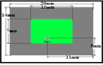
The configuration of reference antenna includes a ground plane of 20 mm × 14 mm and a radiating patch of 10 mm × 7 mm (fig.1). FR4 Epoxy substrate has been used with thickness of 1.6 mm and dielectric constant (Ɛr) of the substrate is 4.4. Here signal is fed to the radiating plane by using coaxial feeding technique.
Fig. 1: Top View of Reference Antenna Design
Fig. 2: Structure of Individual Planes and Top View of Intermediate Design (from left to right)
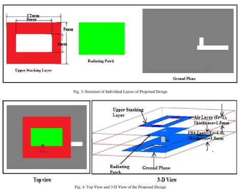
Finally the proposed design is constructed by including a rectangular annular shaped metallic stacking layer at 1.5 mm above the patch. Individual layers, top view and 3-D view of the proposed design are visualized in fig. 3 & fig. 4.
ISSN (Online) : 2319 - 8753
ISSN (Print) : 2347 - 6710
International Journal of Innovative Research in Science, Engineering and Technology
An ISO 3297: 2007 Certified Organization Volume 4, Special Issue 9, July 2015National Conference on Emerging Technology and Applied Sciences-2015 (NCETAS 2015) On 21st & 22nd February, Organized by
Modern Institute of Engineering and Technology, Bandel, Hooghly-712123, West Bengal, India
III. RESULTS AND DISCUSSION
When no slot is present as in the reference design (fig. 1), two reflection co-efficient bands exist of percentage bandwidth 7.18 % and 4.43 % centered at 6.82 GHz and 9.94 GHz respectively. From gain characteristics, it is observed that gain is maximum at 9.76 GHz about 3.97 dBi. (fig. 5)
Fig. 5: Reflection Co-efficient Characteristics and Gain Characteristics of Reference Antenna Design
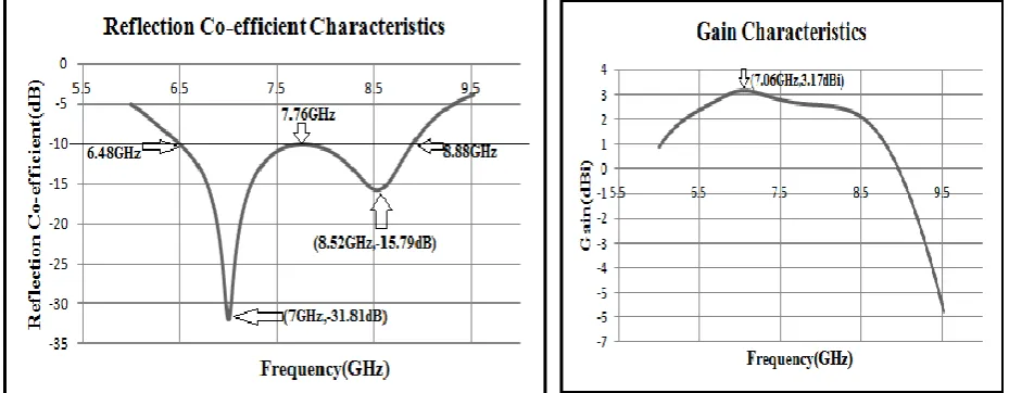
From reflection co-efficient characteristics of the intermediate design (fig.6), a broad band of 31.25% bandwidth is observed in the range from 6.48 GHz to 8.88 GHz with two frequencies of resonance at 7 GHz and 8.52 GHz. Maximum gain obtained in this case is about 3.17 dBi at 7.06 GHz.
Fig. 6: Reflection Co-efficient Characteristics and Gain Characteristics of Intermediate Antenna Design
Fig. 7: Reflection Co-efficient Characteristics and Gain Characteristics of the Proposed Antenna Design
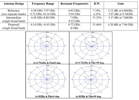
The results can be summarized in table-1 below as,
Table 1: Comparison of Results of Different Designs
Antenna Design Frequency Range Resonant Frequencies B.W. Gain
Reference (two separate bands)
6.58 GHz-7.07 GHz 9.72 GHz-10.16 GHz
6.82 GHz, 9.94 GHz
7.18%, 4.43%
3.12 dBi at 6.86GHz, 3.97 dBi at 9.76GHz Intermediate
(single broad band)
6.48 GHz-8.88 GHz 7 GHz,
8.52 GHz
31.25% 3.17 dBi at 7.06GHz
Proposed (single broad band)
6.14 GHz -8.45 GHz 6.72 GHz,
8 GHz
ISSN (Online) : 2319 - 8753
ISSN (Print) : 2347 - 6710
International Journal of Innovative Research in Science, Engineering and Technology
An ISO 3297: 2007 Certified Organization Volume 4, Special Issue 9, July 2015National Conference on Emerging Technology and Applied Sciences-2015 (NCETAS 2015) On 21st & 22nd February, Organized by
Modern Institute of Engineering and Technology, Bandel, Hooghly-712123, West Bengal, India IV. CONCLUSION
The main observation of the antenna proposed is its broad band of 2.31 GHz extending from 6.14 GHz to 8.45 GHz having two resonant frequencies at 6.72 GHz and 8 GHz with percentage bandwidth of 31.66 %. Maximum gain of 4.20 dBi is discovered at 7.96 GHz. A dual frequency of operation is an additional feature of the design. As gain is nearly same at two resonant frequencies, we can use both the operating frequencies exchangeably in military applications which can provide protection against jamming and ensure higher degree of security. Another point is to be noted that gain is positive (i.e. more than 3 dBi) in the entire operating bandwidth.
REFERENCES
[1] Constantine A Balanis, “Antenna Theory: Analysis and Design”, John Wiley & Sons, Inc., 3rd Edition, Page No. 811-819, 2005.
[2] J. Y. Sze and K. L. Wong, “Slotted rectangular microstrip antenna for bandwidth enhancement,” IEEE Transaction Antennas Propagation Letter, vol. 48, no. 8, pp. 1149–1152, 2000.
[3] K. F. Lee, S. Lung, S. Yang, and A. A. Kishk, “Dual-and multiband U-slot patch antennas,” IEEE Antennas Wireless Propagation Letter, vol. 7, pp. 645–647, 2008.
[4] P. S. Hall, “Probe compensation in thick microstrip patches,” Electron. Letter, vol. 23, pp. 606–607, 1987.
[5] K. Mandal, S. Sarkar, and P. P. Sarkar, “Bandwidth enhancement of microstrip antennas by staggering effect,” Microwave Optical Technology Letter, vol. 53, no. 10, pp. 2446–2447, 2011.
[6] C.K. Wu and K.L. Wong, “Broadband microstrip antenna with directly coupled and parasitic patches,” Microwave Optical Technology Letter, vol. 22, no. 5, pp. 348–349, 1999.
[7] H. F. Pues and A. R. Van De Capelle, “An impedance-matching technique for increasing the bandwidth of microstrip antennas,” IEEE Transaction Antennas Propagation, vol. 37, pp. 1345–1354, 1989.
[8] Tanumay Mandal, Susanta Mahato, Partha Pratim Sarkar, Shuvodip Majumdar, Gobinda Sen, “Analysis of a Novel Shaped Compact Microstrip Antenna for Ultra Broad Band Applications”, International Conference on Computation and Communication Advancement (IC3A), pp.271-274, 2013.
[9] Kaushik Mandal and Partha Pratim Sarkar, “High Gain Wide-Band U-Shaped Patch Antennas With Modified Ground Planes”, IEEE Antennas Wireless Propagation Letter, vol. 61, no. 4, pp-2279-2282, april- 2013.
[10] Nishiyama, E.; Aikawa, M.; Egashira, S., "Stacked microstrip antenna for wideband and high gain," Microwaves, Antennas and Propagation, IEEE Proceedings, vol.151, no.2, pp.143, 148, Apr-2004.
[11] Abbou, D.; Touhami, R.; Gaoua, S.; Tan Phu Vuong, "High gain microstrip antenna based on double superstrate layer for 60GHz
communication systems," Multimedia Computing and Systems (ICMCS), 2014 International Conference on , vol., no., pp.1384-1387, 14-16 April 2014.