A New Design Method for Patch Antenna with Low RCS
and High Gain Performance
L.-L. Cong*, X.-Y. Cao, W.-Q. Li, and Y. Zhao
Abstract—In this letter, a new design for patch antenna, which can obtain low radar cross section (RCS) and high gain performance simultaneously, is proposed on the basis of a metamaterial (MTM) superstrate. The superstrate consists of two metallic layers with different patterns on both sides of a dielectric substrate. Low reflection and transmission are obtained from the upper surface which can absorb most of the incident wave to reduce the antenna RCS. The bottom surface, which has partial reflectivity, is used to construct a Fabry-Perot resonance cavity with the ground plane of the patch antenna to improve its directivity. Measured results show that the proposed antenna can achieve RCS reduction in a broad frequency band ranging from 2 to 14 GHz with maximum RCS reduction value of 28.3 dB, and high gain performance is enhanced by 4.3 dB at most compared with the original antenna in the working frequency band extending from 10.9 GHz to 12 GHz. The measured results agree well with the simulated ones.
1. INTRODUCTION
With the rapid development of stealth and detection technology, radar cross section (RCS), which is regarded as a measurement of target stealth capability, has drawn increasingly growing concern. Due to the development of stealth technology, RCS of the airborne platform has declined significantly, while considerable scattering from antenna has been the bottleneck to improve the stealth capability of the whole system. So far many methods have been brought up to reduce the antenna RCS, such as geometrical shaping [1] and adopting radar absorbing material (RAM) [2–4]. As the sole device for communication on the platform, the antenna must assure effective radiation of electromagnetic (EM) wave firstly. However, the above two methods, especially conventional radar absorbers cannot meet the need because of their negative influence on antennas’ radiation performance. Consequently, it is a severe challenge to reduce the RCS without degrading the radiation performance of antennas.
The rise of artificial composite materials, including frequency selective surfaces (FSS), artificial magnetic conductor (AMC), electromagnetic band-gap (EBG) and perfect metamaterial absorber (PMA), provides a feasible approach to design low RCS antennas because of their exotic electromagnetic properties [5–7]. The investigation of artificial composite material into EM wave absorbers opens a promising door to balance the performance of radiation and scattering. In [8], instead of metal ground plate, the FSS is fabricated as the ground plane of the patch antenna to reduce the backward scattering because of its nearly full reflection in the working frequency band and nearly full transmission out of the working frequency band. In [9], FSS and polarization selective surface (PSS) are applied in the antenna hybrid-radome to achieve RCS reduction out of the operation band. In [10], owing to the application of EBG RAM loaded with lumped resistances to ridged waveguide slot antenna array, in-band RCS reduction is achieved on the basis of Salisbury screen, while disappointingly causing gain degradation in the operation band. In [11], based on the principle of passive cancellation, the reflection screen
Received 28 January 2015, Accepted 23 March 2016, Scheduled 4 April 2016
* Corresponding author: Li-Li Cong ([email protected]).
composed of AMC and perfect electric conductor (PEC) surface is employed as ground plane to reduce the in-band RCS. In [12], a design for waveguide slot antenna with ultra-thin PMA is investigated, which achieves a good RCS reduction in mainly forward direction over 12 dB. In [13], due to the application of mushroom-like EBG structure to patch array antenna, in-band RCS has decreased by 8.2 dB and mutual coupling has also been suppressed. In [14], with the introduction of partially reflecting surface to superstrate coupled with the integration design of the antenna, the performance of the antenna is improved dramatically. In [15], a novel PRS-based patch antenna is proposed, which can achieve low RCS and high gain at the same time. Four resistors mounted on each side of a metallic square loop are used to absorb most of the incoming wave, while a metallic plane with three parallel slots etched on the bottom side of the substrate is used to construct a Fabry-Perot cavity with the ground plane to enhance the gain.
In this letter, a novel design for patch antenna with a metamaterial superstrate is presented. The superstrate is composed of two metallic layers with different patterns on both sides of a dielectric substrate, whose upper and bottom surfaces would have different transmission and reflection responses when illuminated by a plane wave. Low reflection and transmission is obtained from the upper surface which can transform the EM wave energy into heat, consequently reducing the antenna RCS. The bottom surface combined with the ground plane of the patch antenna, are utilized to construct a Fabry-Perot resonance cavity to improve antenna directivity. The prototype is simulated, manufactured and measured. Both simulated and measured results show that the proposed antenna can achieve RCS reduction in a broad frequency band and gain enhancement in the working frequency band in comparision with the original antenna.
2. DESIGN AND CHARACTERISTICS OF MTM SUPERSTRATE
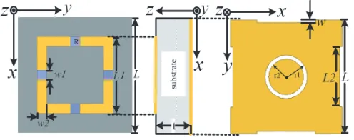
The schematic model and geometric parameters of the forementioned superstrate unit cell are illustrated in Fig. 1. A metallic square loop loaded with lumped resistances on each side comprises the absorbing surface, which can absorb most of the incoming wave by transforming the incident EM wave into heat as Ohm loss. The metallic pattern on the bottom side of the superstrate forms the reflective surface. The reflective surface together with the ground plane construct the Fabry-Perot resonance cavity, of which the partial reflectivity guarantees the antenna gain enhanced based on multiple reflections between the reflective surface and the ground plane. The dielectric spacer is FR4 substrate with relative permittivity εr= 4.4 and loss tangent tanδ = 0.02. According to optimization by adjusting geometry, the parameters are given as follows: L = 12 mm, L1 = 8 mm, L2 = 6.8 mm, w = 0.1 mm, w1 = 1 mm, w2 = 1 mm, t= 3.5 mm, r1 = 2.4 mm,r2 = 2.25 mm,R= 130 Ω.
Figure 1. Unit cell geometry.
slightly. The electric field distribution shows that a strong electric field resonance is produced along x and y axis for x and y polarization respectively. The electromagnetic wave transmits through the substrate by electromagnetic coupling between absorbing surface and reflective surface as shown in the inset of Fig. 3. The simulation results indicate that partial reflectivity characteristic can be achieved for both xand y polarization.
Figure 2. Simulation model of the superstrate.
Figure 3. Simulated reflection coefficient of the reflective surface. Inset: Electric field distribution on the reflective surface at 11.7 GHz.
On the other hand, the case of the incident plane wave propagating from +z to −z is considered. Fig. 4 depicts the reflection and transmission characteristics. As can be seen from the figure, both the reflection and transmission are less than −10 dB from 5.78 GHz to 11.34 GHz for x polarization. The absorption can be calculated byA= 1− |S11|2− |S21|2, from which we can conclude the absorptivity is
over 81% in the above frequency band, as shown in Fig. 5. A similar picture was seen forypolarization in a broader frequency band, where the absorptivity is over 88%. Based on the simulated results, the conclusion that the absorbing surface can absorb most of the incident wave with high efficiency can be drawn.
Figure 4. Simulated reflection and transmission of the absorbing surface.
3. APPLICATION OF THE SUPERSTRATE IN PATCH ANTENNA 3.1. Simulation
The geometrical model of the patch antenna with superstrate is portrayed in Fig. 6. The patch antenna fed by a coaxial probe is adopted as the exciting source, of which the substrate is Taconic TLY (εr = 2.2 andtanδ = 0.0009) with a thickness of d = 2 mm. Since the resonant frequency and the structure of the superstrate are fixed, the distance h has become the key factor to balance the radiation and scattering performance of the proposed antenna. The distance h is given by h = λ(∠φ1+∠φ2)
4π −d √
εA + kλ2 , k = 0,1,2, . . . [15], where ∠φ1 and ∠φ2 are the reflection phases of
the reflective surface and the metallic ground plane, respectively. The distance h is finally settled on 12.9 mm through optimization.
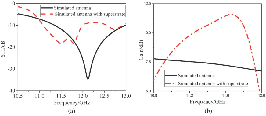
The radiation performances of the patch antenna with and without the superstrate are presented in Figs. 7(a) and (b). Compared with the original antenna of which the bandwidth for S11 <−10 dB
is from 11.47 GHz to 12.98 GHz, the resonant frequency of the proposed antenna shifts towards lower frequency and the bandwidth forS11<−10 dB is narrowed, ranging from 11 GHz to 12 GHz. However,
Patch antenna
Radiation wave Incident wave
Reflective surface Absorbing
surface
t
h z
y x
(a)
(b)
Figure 6. Patch antenna with the superstrate. (a) Schematic view. (b) Simulated model.
(a) (b)
due to the multiple reflections between the reflective surface and the ground plane, the gain of the proposed antenna is improved in the whole frequency band, extending from 11 GHz to 11.93 GHz. The maximum gain enhancement reaches about 4.3 dB around 11.66 GHz.
The E- andH-plane radiation patterns of the proposed antenna are shown in Figs. 8(a) and (b), where the results of the original one are presented as a comparison. The simulated results make it clear that the directivity has been improved obviously with antenna gain enhanced for bothE- andH-plane.
(a) (b)
Figure 8. Simulated results of radiation patterns at 11.66 GHz. (a) E plane. (b)H plane.
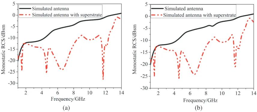
The simulated monostatic RCS as a function of frequency for the patch antenna with and without the superstrate is given in Fig. 9 for bothx and y polarization. The simulated results show explicitly that the proposed antenna can achieve obvious RCS reduction in a broad frequency band covering from 2 GHz to 14 GHz, where the maximum value of the RCS reduction can reach 26.7 dB and 20.5 dB, respectively, which show further evidence that the proposed antenna can meet the requirement of low RCS over a wide band for x andy polarization.
(a) (b)
Figure 9. Simulated RCS as a function of frequency. (a) x polarization. (b)y polarization.
3.2. Measurement
Figure 10. Fabricated antenna and measurement circumstance and setup.
Figure 11. MeasuredS11 results as a function of frequency.
performance of the fabricated antenna, theS11 is measured using the vector network analyzer Agilent
N5230C, which presents very good impedance matching around 11.2 GHz, as shown in Fig. 11. The bandwidth forS11<−10 dB of the fabricated antenna is 1.1 GHz, extending from 10.9 GHz to 12 GHz,
which is 0.1 GHZ deviation from the simulation due to the fabrication error and measurement error. The measured resonant frequency of the fabricated antenna shifts towards lower frequency in comparison with the original antenna, which is consistent with the simulated results. The consistency between the measurement and the simulation verifies the reliability and correctness of overall design schemes.
TheE- andH-plane radiation patterns of the fabricated antenna are shown in Figs. 12(a) and (b), respectively. The measured results agree well with the simulated ones. Compared with the original antenna, the antenna gain gets a maximum enhancement of 3.9 dB and 4.27 dB for E- and H-plane, respectively. The test results indicate that with the introduction of the superstrate, the main lobe of the antenna is narrowed distinctly, and then the antenna directivity improved.
(a) (b)
Figure 12. Measured results of radiation patterns at 11.2 GHz. (a)E plane. (b) H plane.
2 4 6 8 10 12 14
-30 -20 -10 0 10 Mo n o st at ic RCS /d B Frequency/GHz measured antenna
measured antenna with superstrate
2 4 6 8 10 12 14
-40 -30 -20 -10 0 10 Mo n o st at ic RCS /d B Frequency/GHz measured antenna
measured antenna with superstrate
(a) (b)
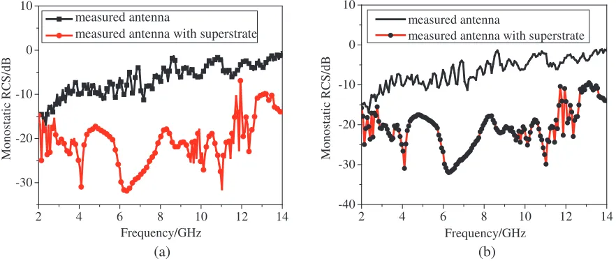
Figure 13. Measured RCS results as a function of frequency. (a) Horizontal polarization. (b) Vertical polarization.
as a comparison. As can be seen from the figures, for the case of horizontal polarization, which is correspond toxpolarization in the simulation of unit, the monostatic RCS is reduced sharply in a wide frequency band covering from 2 GHz to 14 GHz. The value of the RCS reduction is 21.1 dB at 4 GHz, 22.7 dB at 6 GHz and 28.3 dB at 11 GHz in detail. Similar results can apply to the case of the incident wave with vertical polarization (y polarization in the simulation of unit), where the RCS reduction can reach 24.1 dB at most around 11 GHz. The measured results keep a well agreement with the simulated ones, which verifies the feasibility of the superstrate on RCS reduction.
4. CONCLUSIONS
performance of traditional antenna, which means achieving low RCS and high gain simultaneously. Meanwhile, the characteristic of polarization insensitivity produced by the symmetric unit cell design means that it is very likely to present a better performance when the new structure is applied to a patch antenna with circular polarization.
REFERENCES
1. Jiang, W., S. X. Gong, T. Hong, and X. Wang, “Fan-shaped antenna with low RCS for ultra-wideband application,” Acta Electronic Sinica, Vol. 38, 2162–2165, 2010.
2. Yang, H. H., X. Y. Cao, J. Gao, T. Liu, J. J. Ma, X. Yao, and W. Q. Li, “Design of low radar cross section microstrip antanna based on metamaterial absorber,” Acta Physica Sinica, Vol. 62, 0641031–0641037, 2013.
3. Pozar, D. M., “RCS reduction for a microstrip antenna using a normally biased ferrite substrate,” IEEE Microw. Guided Wave Lett., Vol. 2, 196–198, 1992.
4. Yang, J. and Z. Shen, “A thin and broadband absorber using double-square loops,”IEEE Antennas and Wireless Propagation Letters, Vol. 6, 388–391, 2007.
5. Ma, Y., Q. Chen, J. Grant, et al., “A terahertz polarization insensitive dual band metamaterial absorber,” Optics Letters, Vol. 36, 945–947, 2011.
6. Genovesi, S., F. Costa, and A. Monorchio, “Low profile array with reduced radar cross section by using hybrid frequency selective surfaces,”IEEE Transactions on Antennas and Propag., Vol. 60, 2327–2335, 2012.
7. Weiglhofer, W. S. and A. Lakhtakia, Introduction to Complex Mediums for Optics and Electromagnetics [M], SPIE Press, Bellingham, 2003.
8. Genovesi, S., F. Costa, and A. Monorchio, “Low profile array with reduced radar cross section by using hybrid frequency selective surfaces,”IEEE Transactions on Antennas and Propag., Vol. 60, 2327–2335, 2012.
9. Zhou, H., S. B. Qu, B. Q. Lin, et al., “Filter-antenna consisting of conical FSS radome and monopole antenna,”IEEE Transactions on Antennas and Propag., Vol. 60, 3040–3045, 2012.
10. Li, Y. Q., H. Zhang, Y. Q. Fu, et al., “RCS reduction of ridged waveguide slot antenna array using EBG radar absorbing material,” IEEE Antennas and Wireless Propagation Letters, Vol. 7, 473–476, 2008.
11. Tan, Y., N. Yuan, Y. Yang, and Y. Fu, “Improved RCS and efficient waveguide slot antenna,” Electronics Letters, Vol. 47, 582–583, 2011.
12. Liu, T., X. Y. Cao, J. Gao, Q. R. Zheng, W. Q. Li, and H. H. Yang, “RCS reduction of waveguide slot antenna with metamaterial absorber,” IEEE Transactions on Antennas and Propag., Vol. 61, 1479–1484, 2013.
13. Zhang, J. J., J. H. Wang, and M. E. Chen, “RCS reduction of patch array antenna by electromagnetic band-gap structure,” IEEE Antennas and Wireless Propagation Letters, Vol. 11, 1048–1051, 2012.
14. Ge, Y., K. P. Esselle, and T. S. Bird, “The use of simple thin partially reflective surfaces with positive reflection phase gradients to design wideband, low-profile EBG resonator antennas,”IEEE Transactions on Antennas and Propag., Vol. 60, 743–750, 2012.