An Intelligent Battery Management System Based on
SOC for Microgrid Employed In Grid-Connected Mode.
Kalyan Kumar Koppolu
1, Srinivas Nakka
2, A. Ananda Kumar
3,
EEE Department1,2,3,Vardhaman College of Engineering1,2,3
Email: [email protected]1 ,[email protected]2,[email protected]
Abstract- As of late, sustainable power source has been largely coordinated into control environments and reduced scale frameworks. The irregular power infusion will influence the stability of the power system, particularly for the little scale ones. Since the sustainable power sources are unchallengeable sources of supply the energy storing system assumes a critical part in dealing with the power stream amongst every component of the Microgrid by keeping the SOC of the ESS under safe locale. In this paper, an examination of voltage & frequency (V&F) based BMS controller and voltage source converters (VSCs) are being utilized as a part of network-coordinated control in smaller scale network for investigating the ideal capacity of plant under transient conditions. This battery management system utilized as a part of Microgrid operating in a grid-connected mode to control over exchange of Real power is achieved by using SOC. A PV generator, Battery storage system and Loads form the Microgrid. This Microgrid is situated a normal sun oriented radiation more noteworthy of 1000 W/m2. In this investigation, the test system contains PV cells, Battery, Nonlinear load, RL load and Grid has been reproduced in Matlab/Simulink. Index Terms- Microgrid, State of Charge(SOC), PV cell, Voltage source converters (VSCs), Sustainable power source, Energy Storage Source (ESS).
1. INTRODUCTION
Microgrid frameworks coordinate distributed generation (DG) components, energy storage systems (ESS) and well-regulated loads on a small voltage organize which is able to work in either grid connected mode or remain isolated mode. In lattice associated mode, the Microgrid changes control adjust of supply and request by obtaining power from the principle matrix or offering energy to the principle framework. The discontinuity of disseminated inexhaustible age postures huge difficulties for the operation and reconciliation of Microgrid. To ease the control vacillations of non-dispatch able DG units, different control plans are utilized as a part of Microgrid, including power direction of each dispatch able Distributed Generating unit, charging and discharging of ESS, and load shedding.
Battery Administration or Management systems (BMS) are indispensable in the utilization of Microgrids. Over the previous decade scientists have created distinctive techniques for BMS. One of the procedure is the SOC-based Management systems, In expansion, a typical procedure for BMS is to utilize an inverter as a vitality administration framework, the vitality from the dc-connection can be engaged into a DC– AC inverter to bolster the vitality in the network, on the other hand this vitality can be put away into the battery for crisis cases. With the quick improvement of Renewable vitality sources (RES), a microgrid show up as a practical answer for an organized mix of RES into a low voltage DC control framework [1]. Be that as it may, the stochastic conduct of the RES, for example, photovoltaic (PV) generators, requires the coordination of more vitality stockpiling frameworks (ESS) with a specific end goal to smooth the varieties at the RES [2]. Indeed, when monetary and ecological issues don't permit interconnection with the
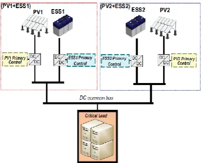
fundamental power framework, the limit of the ESS should be expanded keeping in mind the end goal to guarantee a few to numerous hours of vitality hold [3]. Therefore, the present pattern is arranged to the coordination of disseminated RES and its comparing ESS as a unit meant as dynamic generator (PV & ESS) [2], [4].Fig. 1 demonstrates the fundamental plan of an islanded DC microgrid made by two (PV& ESS) dynamic generators and a basic load. Normally, valve controlled lead-corrosive (VRLA) batteries are the most utilized as a part of islanded microgrids, since they offer a decent duty between vitality thickness, profound cycle life, transportability, accessibility, and cost [3], [5].
At the point when circulated ESS are utilized, it is prescribed a facilitated operation between them so as to keep away from profound discharge in one of the vitality stockpiling entity and over-charge in the others. Contrasts at the SoC might restrict the life-time of the ESS with the littlest SoC, since this ESS will be presented to greater profound of release [6]. In this way, when the ESS are being charged, it is attractive to organize the accuse of the ESS of the littlest condition of charge (SoC), and on the contrary, when the ESS are being released, the unit with the most noteworthy SoC ought to give more energy to the microgrid than the others keeping in mind the end goal to guarantee put away vitality adjust [7], [8].
The Microgrid can be characterized as dispersed age based network that contain both age and loads. For smooth and stable operation it is important to keep up the voltage and recurrence of Microgrid. To control the voltage also, recurrence a wide range of control procedure can be actualized, for example, (I) Master /slave control (ii) hang control. The voltage and recurrence can be kept up at wanted level by utilizing both Master /slave control and hang based control. Hang based control procedure is productive than the Master /slave control. In a Microgrid, at whatever point the issue related with the soundness for the diverse blame levels the term islanding comes in to the photo. At whatever point blame happens on the utility lattice, Microgrid is disengaged from utility lattice which is known as islanding [9]. One more critical point to be advised, while interfacing Microgrid to utility lattice voltage and recurrence ought to be kept up at PCC. (Purpose of regular coupling). The security at PCC is essential for control trades amongst Microgrid and utility network [10]. This paper depicts the power trades between Microgrid and utility framework at various stacking condition. It is likewise demonstrated that the power which the Microgrid goes near island mode. Managing a vitality adjust amongst age and utilization, the Microgrid control has decides that are agreeing with sunlight based irradiance, the condition of charge of the vitality stockpiling system and the ON-loads in the private gathering. The Microgrid demonstrate is characterized beneath keeping in mind the end goal to create these standards.
The voltage source converters control the movement of Active and Reactive powers between the Microgrid and utility grid [8] [9]. Therefore, the first thing is to
see which variables effect the flow of Active and Reactive powers. The voltage source converter can generate voltage of any magnitude at desirable phase (Fig. 2). The flow of real and reactive power from the Microgrid to the utility grid is determined by vector relation between inverter output voltage and utility grid voltage along with line reactance. The flow of Active and Reactive powers can be controlled by generating the suitable values for two variables of δi* and Vi* from below Equations.
Fig 2: Basic structure of the VSC connected to Grid
sin(δi-δG)
2.1. PV System Configuration and Control
The PV system setup for voltage control with PV working at Maximum Power Point (MPP) with the battery move down capacity associated with the DC connect. It is a two phase arrangement where a DC-DC support converter is utilized for MPPT control. The framework additionally uses battery move down to supplement the PV while keeping up the microgrid voltage what's more, recurrence or providing basic burdens. The PV framework is related with the structure through a coupling resistor inductor. The coupling inductor filter through the swells in the PV yield current. The affiliation point is known as the Point of Common coupling (PCC); PV source is related with the DC association of the inverter with a capacitor. The PV is the dynamic power source, and the capacitor is the responsive power wellspring of the PV framework. Most extreme Power Point Tracking (MPPT) is done in perspective of the Perturb and Observe Method notwithstanding fundamental.
2.2.Battery Modelling and Control
destructive one with appropriate determination of parameters for significant cycle application. It is normal that the lead destructive battery can be discharged up to SOC of 30% and can be stimulated to SOC of 80%. The battery reinforcement is considered for brief term applications like repeat control and giving vitality to fundamental loads if there should be an occurrence of crisis conditions. One hour of battery fortification is believed to be adequate for other support generators to accept control over the controls in the Microgrid crisis conditions. The battery is related in parallel to the PV Array to infuse dynamic power through a bidirectional DC-DC boost converter. The battery is charging and Discharging, decided by the charging limits of the SOC algorithm which has been set between 30%-80% of the rating, the min limit is taken to keep the battery from the dry situation and the max. limit is kept to use the battery efficiently for feeding the load. The power flows from Microgrid to Voltage Source converter and Loads, also the battery injects power to the grid, as its operating based on SOC percentage and further Load range. Initially the process starts with the PV power output which is 100 kW and if Load is lower than this then the battery gets charges to the maximum limit, the logic will send a flag to work the boost converter associated with the battery to charge mode additionally relying upon the SOC. Then again, if the load is more noteworthy than the PV yield and the battery will be in release mode, a rationale is utilizedtoguarantee that the logic is sent to the battery to start the release procedure for taking care of the Load demand. The PWM generator is controlled in view of the PV control yield, inverter and battery control yield. The converter controls are in such route as to ensure the required voltage at the PCC. Hence the control signals make use of the consider dynamic and responsive power at the PCC.
2.3.Voltage Source Converter’s (VSC) PQ control
In d-q frame , d-axis (Id*) is in phase with the utility grid voltage, which is mindful to control δ henceforth controlling the real power. While Iq* is mindful to turn at the precise key recurrence ω of the framework voltage waveform. The state-vectors which prompts the inverter electrical amounts are anticipated on the
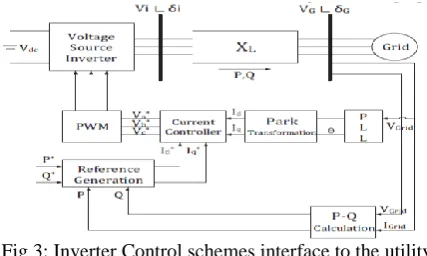
d-axis and q-axis. The inverter is well-ordered utilizing the time-integral of the d-q space vector. The d-q segments are incorporated w.r.t time brings about motion vectors of PI input. The P-Q control is executed through the current controller. The outline block of the VSI P-Q controller is appeared in Fig 3. Synchronous reference outline control too called d-q control utilizes a reference outline change "abc to dq" which changes the network current and voltages into d-q outline. The transformed current controls the utility grid current.
Fig 3: Inverter Control schemes interface to the utility grid
The prime essentialness of this generator, which can be Solar based or batteries, is traded as AC control through a VSI converter that uses a shrewd control framework. The control system employments a PLL square and inward control circles of current and voltage to ensure the individual reference signals. The yield current and voltage reference signals are organized by an outer control hover of sharing force which uses the basic idea of the synchronous generator thought to control the sharing force by using hang bends ("P versus f" and "Q versus V").
2.4.Battery Management System for Microgid
working in Grid Connected Mode
of the SOC requests reaction and access to the electrical grid for when is required.
3. TEST SYSTEM DESCRIPTION AND
RESULTS
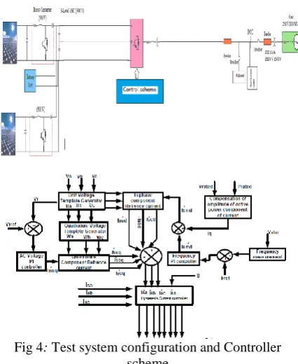
The test system layout is shown in Fig. 4. Following is a description of the different system components and configuration.
3.1 Grid Connected Mode
The contextual investigation of Microgrid with RL and Nonlinear Loads are reproduced for two distinct conditions. The main contextual investigations for wanted responsive load power and second contextual analysis where Microgrid in Utility grid connected mode, generates the power which is really required for Loads. The accompanying parameters can be utilized for plan the Microgrid.
Fig 4: Test system configuration and Controller scheme
For the main contextual investigation, the load demanding active power is set to PL = 100KW & the reactive power is set to QL =40Kvar. For this situation Microgrid connected with battery storage system is able to supplied the power to Loads as well as utility Grid, which is shown in Fig. 6 &Fig.7(Positive Active Power to Main Grid). From Fig.5. in SOC %(state of charge) it is observed that the battery has been discharged. It can also be seen from fig.8.that inverter maintains voltage with constant value.
Fig 5: Battery Current ,Voltage and State Of charge
Fig 6: Active Power Delivered from Micro Grid
Fig 7: Active Power Delivered from Utility Grid
Fig 8: DC Input Voltage to an Inverter
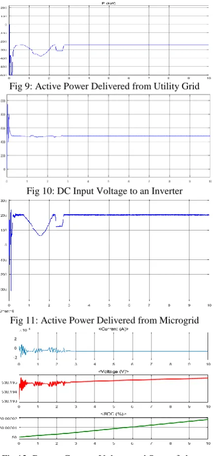
Fig 9: Active Power Delivered from Utility Grid
Fig 10: DC Input Voltage to an Inverter
Fig 11: Active Power Delivered from Microgrid
Fig 12: Battery Current, Voltage and State of charge Under Light Loaded Condition.
Fig 13: Active Power Delivered from Utility Grid Under Light Loaded Condition.
Fig 14: Transient waveform of micro grid with BESS based VFC feeding non-linear load and removal off
one plant
3.2. APPENDIX
Parameter Symbol/Type Value Irradiance Ir(w/m2) 1000w/m2 Solar panel PV array
with P&O
500V
Battery Nickel- Metal-Hydride
500v,1Ah
Utility Grid 3ph Ac source
120KV,2500MVA
Grid Transmission
Line
Pi section 19km
Loads at Utility Grid
RL, R 30MW,2Mvar and 2MW Loads at
PCC
RL and 3ph diode rectifier
Custom
3. CONCLUSION
mind the end goal is to optimize the Real power transfer according to the Load ranges, and by considering the power constraints of the configuration. Also, the calculation can be effortlessly adjusted for Microgrid working in Grid connected Mode. Microgrids are regularly arranged with additional limit regarding the Local load. This additional power limit can be infused once again into the Utility Grid network with a specific end goal to acquire some financial advantage. Lattice interconnection permits to decrease fuel operational expenses by utilizing the network around evening time when power costs are low. The BESS controller additionally works agreeably amid expulsion off of one micro source yet as the entire system is associated in parallel other controller shares the load and henceforth keeps up the voltage & frequency of the entire system constant.
REFERENCES
[1] Luis E. Zubieta,ARDA Power Inc.Oakville, Ontario, CANADA, Power Management and Optimization Concept for DC Microgrids, 2015 IEEE.
[2] I. Mpawenimana, M. D. Fazio, C. Belleudy, A. Z. Ya W. T Soe,"Energy Management System and InteractiveFunctions of Smart Plug for Smart Home ," WASET, vol. 11, 2017.
[3] D. Sez, F. vila, D. Olivares, C. Caizares, and L. Marn, “Fuzzy prediction interval models for forecasting renewable resources and loads in microgrids,” IEEE Transactions on Smart Grid, vol. 6, no. 2,pp. 548–556, March 2015..
[4] J. Zhang, Q. Wang, C. Hu, and T. Rui, “A new control strategy of seamless transfer between grid-connected and islanding operation for micro-grid,” in 2017 12th IEEE Conference on Industrial Electronics and Applications (ICIEA), 2017, pp. 1729-1732.
[5] M. Xin, Z. Liu, J. Liu, W. Teng, W. Shike, and L. Baojin, “A seamless transfer strategy based on special master and slave DGs,” in 2017 IEEE 3rd International Future Energy Electronics Conference and ECCE Asia (IFEEC 2017 - ECCE Asia), 2017, pp. 1553-1558.
[6] H. Kanchev, D. Lu, F. Colas, V. Lazarov, and B. Francois, “Energy management and operational planning of a microgrid with a pv-based active generator for smart grid applications,” IEEE Transactions on Industrial Electronics, vol. 58, pp. 4583–4592, Oct 2011.
[7] J. de Matos, F. e Silva, and L. Ribeiro, “Power control in ac isolated microgrids with renewable energy sources and energy storage systems,” IEEE Transactions on Industrial Electronics,, vol. PP, no. 99, pp. 1–1,2014.
[8] F. Marra, G. Yang, C. Traeholt, J. Ostergaard, and E. Larsen, “A decentralized storage strategy for residential feeders with photovoltaics,” IEEE Transactions on Smart Grid, vol. 5, pp. 974–981, March 2014.
[9] I. S. C. Committee, “Ieee guide for optimizing the performance and life of lead-acid batteries in remote hybrid power systems,” 2008
[10] Y.-K. Chen, Y.-C. Wu, C.-C. Song, and Y.-S. Chen, “Design and implementation of energy management system with fuzzy control for dc microgrid systems,” Power Electronics, IEEE Transactions on, vol. 28,no. 4, pp. 1563–1570, 2013.
[11] J. Guerrero, J. Vasquez, J. Matas, M. Castilla, and L. de Vicuna, “Control strategy for flexible microgrid based on parallel line-interactive ups systems,” IEEE Transactions on Industrial Electronics, vol. 56,no. 3, pp. 726–736, 2009.life of lead-acid batteries in remote hybrid power systems,” 2008.
[12] J. A. Lopes, C. Moreira, and A. Madureira, “Defining control strategies for Microgrids islanded operation,” IEEE Trans. Power Syst., vol. 21,no. 2, pp. 916–924, May 2006.
[13] V. S. Tejwani, B. N. Suthar, “Novel Control Strategy for Gridconnected PVES for Smart Distribution System” Fifth International Conference on Power and Energy Systems, Kathmandu, Nepal 28 – 30 October, 2013. [14] H. Li, F. Li, Y. Xu, D. T. Rizy, and S. Adhikari,
“Autonomous and adaptive voltage control using multiple distributed energy resources,” IEEE Trans. Power Syst., vol. 28, no. 2, pp. 718–730, May 2013.
[15] P. Monica School of Electrical Engineering, VIT University Vellore, India; M. Kowsalya ; K. Subramanian, “The application of demand response for frequency regulation in an islanded microgrid with high penetration of renewable generation” in 2017 Innovations in Power and Advanced Computing Technologies Miao, and L. Fan, “Coordinated control of a solar battery system in amicrogrid,” in Proc. 2012 IEEE/PES Transm. Distrib. Conf.Expo. (T&D), pp. 1–7. [16] Adhikari, Sarina, and Fangxing Li. "Coordinated
Vf and PQ control of solar photovoltaic generators with MPPT and battery storage in microgrids." (2014): 1-12.
[17] M. G. Villalva, J. R. Gazoli, and E. R. Filho, “Comprehensive approach to modeling and simulation of photovoltaic arrays,” IEEE Trans. Power Electron., vol. 24, no. 5, pp. 1198–1208, 2009.
[18] O. Tremblay and L. A. Dessaint, “Experimental validation of a battery dynamic model for EV applications,” World Electric Vehicle J., vol. 3,2009.