96
Sensor based Line Follower Self-Driving Car (sCar) with Obstacles
Avoidance
Md. Nazrul Islam
1, Jaime Gallardo-Alvarado
2, Othman bin Ahmad
1, Ali Farzamnia
1and Zakariah Aris
31Faculty of Engineering, Universiti Malaysia Sabah , Jalan UMS, 88400 Kota Kinabalu, Sabah, Malaysia. 2Department of Mechanical Engineering, Instituto Tecnológico de Celaya, Av. Tecnológico y A. Celaya 38010,
Gto., México.
3Faculty of Computing and Informatics, Universiti Malaysia Sabah, Jalan UMS, 88400 Kota Kinabalu, Sabah,
Malaysia.
Email: [email protected] (or) [email protected]
Article Information
Abstract
Keywords
Sensor, Line follower, Self-driving car, Obstacles, Avoidance
This paper introduces the sensor based line follower Self-driving Car (sCar) with obstacles avoidance. We develop a Collision Avoidance path-planning Algorithm (CAA) for dual motors controller line follower sCar that has ability for navigate collision avoidance path autonomously through a constraint track from initial position to goal position. A sensor will be mounted in front of the sCar that will detect line and obstacles along the track. A powerful close loop control system is used in the sCar which can calcules collision free path. The sCar senses a line and endeavors a collision free path itself accordingly towards the initial position to desired goal position using a simple feedback mechanism but yet very effective closed loop system. In some situation, there will be multiple destinations and the sCar should able to choose the desired destinations based on CAA applied to the microcontroller Arduino UNO which acts as the center control unit. The CAA will be implemented by C++ programming language. Evaluation results show that CAA calculates collision free path with constant performance which independent on environments.
INTRODUCTION
97
To overcome these difficulties, we develop a Collision Avoidance path planning Algorithm (CAA) for sCar based on sensor and Minimum Distance Technique (MDT) that calculate collision free path in parallel both static and dynamic environment (Burhanuddin & Islam, 2013). The key mechanism for avoiding collision based on MDT is the one that determine the minimum distance (Computed Minimum Distance (CMD)) between sCar and obstacles, it is necessary to compute the minimum distance between one link segment and another link segment (or edge of obstacles) when a sCar is approaching collide with obstacles. This paper describes a collision avoidance path planning algorithm for sCar, that is collision-free and safe paths. The algorithm is required to:
(1) find safe paths which is collision free between sCar and obstacles.
(2) guarantee path which calculates from multiple initial position to multiple goal position. (3) The maintain memory space.
The simplest collision avoidance algorithms fall into the generate and test paradigm. A simple path from start position to goal position, usually a curve and then the path is tested for potential collisions based on MDT. If Computed Minimum Distance (CMD) is less than given Constraint Minimum Distance, dmin and then collision will occur. If collisions are detected, a new path will calculates, using information which based on sensor and MDT. This is repeated until no collisions are detected along the path. If CMD is greater or equal to dmin then collision will never happen between sCar and obstacles. Where, dmin is set 5m. Roughly, the three steps in this type of algorithm are:
(1) calculate the Computed Minimum Distance (CMD) by MTD. (2) check CMD is greater than dmin .
(3) calculates a path from start position to goal position.
The advantage of CAA is that it calculates collision free path for sCar from multiple start position to multiple goal position in parallel in fully dynamic and static environments.
URGENCY AND OPPORTUNITY OF sCARS
sCars are vital in order to make our mass transportation system workable. It can reduce traffic jams without resorting to long walking distances which will be required if we are to use trains. sCars allow the advantages of trains as used in mass-transportation systems because the drivers can do other things while the car self-drives. The owners' time are also not wasted driving cars in order to send to and pick up their children from schools or other chores which contribute to the massive jams as well. With sharing apps, the self-drive cars can be utilized to earn income for the owners when the cars are not used, which is most of the time, thus reducing the cost of the cars to the owners, to the point that most sCars will be acquired for free on average. With such low cost, owners can afford safe and comfortable cars such as the electric cars which are also environmentally friendly, solving the global warming threat simultaneously. The tremendous success of drive-sharing apps such as Uber that became billion dollar companies show the potential of sharing self-driven cars but unlike human-driven drive-sharing apps, there is no licensing problems because no human drivers are involved. Once the self-driving system is certified safe to be used, which is the most important step in realizing the implementation of any self-driving car, all licensing concerns for drive-sharing will disappear. Immediately, owners of cars will get high quality, safe, comfortable and environmentally friendly cars that improve productivity while on the road at zero cost while solving the traffic congestion and the global warning threat at the same time and immediately. The survival of the human race is assured without hindering any progress, but in fact, assists in making the human race even more advanced with the increase in human productivity as a result of more productive time and less time lost in traffic congestion. sCar can be use in coal mining, rock mining, and etc where human cannot go but sCar can operate easily. It also can operate in highway low speed lane for heavy truck, flatbed truck and cargo delivery truck for transport goods.
COLLISION AVOIDANCE PATH PLANNING ALGORITHM (CAA)
98
goal position of path the the calculation will end otherwise CAA will look for possible another collision-free path in other direction if path exists where overtaking is allow by sCar otherwise no path exist.
TABLE 1
T
HE SPEED OF SCAR WILL CONTROL BY PREDEFINED DATA
Status of collision Speed of sCar(km/h)
CMD>=dmin Safe 50 to 80
CMD<dmin Dangerous stop
Basic Theorem
[Theorem 1] Under the assumption that individual path for sCar at point Hn to Gn are continues connected, the
necessary and sufficient condition for the existence of collision free paths sensor based MDT for a sCar from its start feasible position H = {H0 , H1 , … , Hn} to the goal feasible position G = { H0=G0 , G1 , … , Gn} is that n -reachable set, R(n) and n-reachable path R(n) is a connected continues path that are reachable from starting position, HntoGoal position G0. for each n = 1,2, .. , N. Also when collision free path from H to G exist, Ln , the locus (path) of sCar is the single fixed point { H0 }, and the single fixed point { G0 } can be determined based on sensor detect constraint line follower lane. Here H and G, start and goal position in the follower lane for sCar. When the locus Ln will calculate from start position to goal position and it will be save in memory. The sCar can
reuse this locus Ln without calculate path because this path already calculated but need to detect collision along
the path. This the most important advantage of CAA in this way we can safe memory space and CAA can calculates path use in normal CPU.
The MDT calculated a Computed Minimum Distance (CMD) between sCar to obstacles. The Constraint Minimum Distance, dmin, which is given by user and it will keep save distance for avoiding collision. Where,
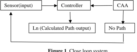
dmin is 5m given by user and it is a collision free safe distance between cSar and obstacles. In usual cases, the moving range of the sCar does not constitute the whole circle so as to avoid collisions between the sCar and the obstacles we apply dmin consequently, arc of circle may vary depend on the obstacle position. For avoiding collision between sCar and obstacles we apply dmin, which detect if any possible collision may occur or not. If CMD is greater than the given distance constraint, dmin, then no collision occur between sCar and obstacle and the terminal position is located in the constraint lane. If this terminal position is a goal position of lane then path calculation will end otherwise CAA will look for possible another collision-free path in other direction if path exists. Figure 1 show the close loop system of sCar.
Figure 1. Close loop system
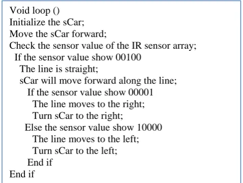
The sCar will move forward if there is no changes from the sensor value. If one of the five sensor value change, the motor will adjust it position to match the sensor value and move according to the track. The movement of the sCar will depend on the different combinations of sensor values and assigned using the weighted values method. Figure 2 shows pseudocode for movement of sCar and movement of sCar is based on the changes value from the IR sensor.
Path Generation
The path calculation is executed every time when the user are given the start and the goal positions of sCar, and based on R(n) and sensor based information, a locus of its initial position Hn to its goal position Dn, is calculated for each n, starting from n = 1 to N. The sensors characterize and a proportional/derivative (PD) control algorithm was developed to make the line following process smooth, fast, and efficient. The number of sensors and DC motors is affecting the smoothness and speed of the mobile robot to navigate itself through the constraint track.
Sensor(input) Controller CAA
99
Figure 2 Pseudocode for movement
Minimum Distance Technique (MDT)
In this section, we briefly discuss the CAA which calculates collision free path avoiding of any obstacles based on MDT and any unnecessary distance computation. CAA developed for MDT based on collision detection and distance computation for sCar from start position to goal position. Collision detection is an important part of path planning for sCar. Collision can occur between a sCar and obstacles in the environment. In this paper, we proposed minimum distance technique for avoiding collision between sCar and obstacles. MDT based obstacle detection and avoidance will enable collision-free path for sCar in R(n) throughout the environment. It will cause a reduction of the computation time.
To avoid collision between two links or points it is sufficient to determine the minimum distance between link (point) to link (point). The minimum distance between two links, it is necessary to compute the minimum distance between one link segment and another link segment Figure 3 illustrates the problem. link 1 is defined by the end-points X1 and X'1 and link 2 is defined by the end-points X2 and X'2, where:
X1 ≡ (x1, y1, z1)
X'1 ≡ (x'1, y'1, z'1)
l1≡ length of link segment 1 = | X'1- X1|
A1≡ direction cosine vector of link 1 = (a1, b1, c1)
A2≡ direction cosines vector of link 2 = (a2, b2, c2)
The parametric equation for infinite line through link segment 1 and 2 are
LX1 : V = X1 + t1A1 ….. (1) LX2 : V = X2 + t2A2 ….. (2)
where V represents the coordinates of any point along the link and tl is a scalar parameter. Link segment 2 has
parameters and an equation analogous to that for link segment 1.
For minimum distance between two link 1 and 2, we want to find the minimum distance, dm,between link 1 and
link 2. We also want to find the points M1 (≡ V) on link 1 and M2 (≡ V) on link 2 corresponding to this
minimum distance. Because (M1 – M2) must be perpendicular to both A1 and A2. Where,
(M1 – M2).A1 = 0 (3) (because M1M2 ┴ A1)
(M1 – M2).A2 = 0 (4) (because M1M2 ┴A2)
Then:
M1 – M2=D12 +t2A2– t1A1 (5)
Where D12 = X1-X2 . Substituting this result into equations (3) and (4) , and solving for t1 and t2
t1 = a + t2b (6)
t2 = ab-c/(1-b2) (7)
Here, b ≠ ±1, where a ≡ D12 .A1, b ≡ A1.A2, and c ≡D12 .A2 . The minimum distance between link 1 and 2, dm,
is simple the distance between the points M1 and M2 corresponding to the parameters t1 and t2 given by
equations ( 6 ) and (7).When a sCar is approaching collision with obstacles, it is sufficient to test for link (point) segment to link (point) segment distance for avoiding collision between sCar and Obstacles.
Void loop () Initialize the sCar; Move the sCar forward;
Check the sensor value of the IR sensor array; If the sensor value show 00100
The line is straight;
sCar will move forward along the line; If the sensor value show 00001 The line moves to the right; Turn sCar to the right;
Else the sensor value show 10000 The line moves to the left; Turn sCar to the left; End if
End if
l1
𝐴
l2
X’
1X
1X
2X’
2100
Another way is very simple, sensor will give distance between sCar and obstacles we called this distance is CMD based on sensor data and for avoiding collision we will check CMD and Dmin which is equal, grater or
less. So, collision free paths from individual start position and goal position can be calculated completely in parallel in these two different avoiding methods
RESULTS AND DISCUSSIONS
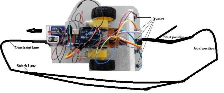
This section presents results of a Collision Avoidance path planning Algorithm (CAA) based on Minimum Distance Technique. In the simulation, the behavior of CAA can be determined and the performance of CAA was tested and evaluated. The simulation of CAA examines in complex environments. The CMD time for collision avoidance and total path length were measured. Here, the computation time is measured for total path length and the total path length means from start position to goal position. There will be total of five IR sensor used. The sensor are arranged in a row so that more track area can be covered. Each sensor provides a separate digital I/O measurable output. The sensor array is calibrated at the beginning of each run to provide references states for maximum and minimum reflectance. The sensor arrangements are illustrated in Figure 4. In evaluation cases, sCar work in 120m long constraint lane and it’s contain multiple start position, goal position and switch lane for change track in particular places only. The algorithm were implemented by C++ Software on Windows 7 running on Intel® Core™ 2 i3 CPU 550 @ 3.20 GHz with 2 GB RAM and 500 GB Hard disk Capacity.
Computed Minimum Distance (Cmd) By Mdt
CMD calculates successfully based on MDT for avoiding collision between sCar to obstacle. In Figure 5 (a)-(b), the dotted straight line shows constraint minimum distance dmin and the curve shows the Computed Minimum Distance (CMD). Where, dmin is 5m given by user and it is a collision free safe distance between sCar to obstacles. Figure 5(a)-(b) shows that CMD between sCar and obstacles. This figures shows that CMD does not cross the dminline it means that no collision occur between sCar obstacles along the path. Therefore, CAA calculated collision free path for sCar successfully.
The above fact leads another advantage of CAA i.e. the computation times are dependent only on the number of obstacles which contains along the path length from start position to goal position. If there are no obstacles on the path in this case the computation time only depends on the speed of sCar. Therefore, the computation time increase if increase the number of obstacles along the path.
101
Figure 5 (a)Distance between sCar and obstacles Figure 5 (b)Distance between sCar and obstacles
CONCLUSION
Based on the experiment and testing, the desired outputs have been achieved. CAA calculated/detected collision free path based on on IR sensor and MDT for obstacle detection. The car successfully detects line and able to navigate itself through the constraint track. A Collision Avoidance path-planning Algorithm (CAA) for manipulator has been developed and evaluated based on Minimum Distance Technique (MDT) that calculate collision free path from start position to goal position. CAA solved collision avoidance problem for sCar between sCar and obstacles based on MDT. The most important advantage of CAA, i.e. it calculated collision free path which can save in memory in CPU and sCar can reuse this path with detect collision of obstacle only. Therefore CAA can maintain its performance at the level theoretically expected.
ACKNOWLEDGMENT
The authors would like to thank the Universiti Malaysia Sabah (UMS) and UMS Research and Innovation Center (PPI) for supporting this research project.
REFERENCES
Buniyamin, N., Wan Ngah, W.A.J., Sariff, N. & Mohammad, Z., (2011) A Simple Path Planning Algorithm for Autonomous Mobile Robots. International Journal of System Application, Engineering and Development, 5(2), PP.151-158
Niveditha, P. R. & Gowri, S. (2014) Collision Warning System using Ultrasonic Sensors. Proc. of Int. Conf. on Recent Trends in Information, Telecommunication and Computing, ITC, PP.419-424.