363 Copyright © 2012 IJECCE, All right reserved
BER Performance Improvement in Multipath Fading
Environment Using Combined Equalizer and Diversity
Techniques
Deepmala Singh Parihar
Prof. Ravi Mohan
Abstract — The wireless communication is impaired by the
multipath fading characteristics and therefore creates the problems in proper reception. Therefore the knowledge of the channel and the type of fading is most important in designing the receiver. The channel estimation has become very vast field due to different types of interference present in wirelesss channel and in equipments. In this thesis, estimation algorithms for digital communications systems in the presence of Additive White Gaussion noise and Multipath environment are explored and their performance is investigated. In particular, Least square Error equalizer and Zero forcing equalizers are used to provide the optimum solution and compensate for Inter-Symbol error. As the BER performance of equalizers in variable in multipath fading channel therefore we have combined Equal Gain combining and Maximal Ratio Combing Diversity techniques, and find that Maximal Ratio combining techniques is able to fight with Co-Channel interference and Inter-symbol interference problem. The above approaches have resulted in big improvement in BER performance.
Key Words — OFDM, Equalizer, Diversity, QAM.
I.
I
NTRODUCTIONThe radio channels in mobile radio systems are usually multipath fading channels, which are causing intersymbol interference in the received signal. To remove intersymbol interference from the signal, much kind of equalizers and diversity algorithm can be used. The wireless radio channel can be parameterized as a combination of paths, each characterized by a delay and complex amplitude. The amplitudes show fast temporal variations due to the mobility of terminals while the delays are almost constant over a large number of orthogonal frequency division multiplexing (OFDM) symbols. A possible approach is that of explicitly estimating and tracking the delay [1].it is well known that the wireless channel causes an arbitrary time dispersion, attenuation, and phase shift in the received signal. The use of OFDM is to mitigate the effect of time dispersion. The function of channel estimation is to form an estimate of the amplitude and phase shift caused by the wireless cannel from the available pilot information. The equalization removes the effect of the wireless channel and allows subsequent symbol demodulation.
OFDM is a special case of multicarrier transmission and it can accommodate high data rate requirement of multimedia based wireless systems. Since channel estimation is an integral part of OFDM systems. As a combination of MIMO-OFDM systems promises higher data rates. OFDM divides the available spectrum into a number of overlapping but orthogonal narrowband sub channels, and hence
converts a frequency selective channel into a non frequency selective channel [2].
II.
OFDM
(O
RTHOGONAL FREQUENCY DIVISION MULTIPLEXING)
OFDM is a multicarrier system uses Discrete Fourier
Transform/ Fast Fourier Transform and sin 𝑥
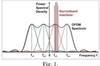
𝑥 spectra for subcarriers. OFDM is becoming widely applied in wireless communications systems due to its high rate transmission capability with high bandwidth efficiency and its robustness with regard to multipath fading and delay [4]. Available bandwidth is divided into very many narrow bands for example 2000-8000 hz for digital TV and 48 hz for hiperlan2 and data is transmitted in parallel on these bands. OFDM method is so popular for new broadband systems are subject to multipath transmission.
Fig. 1.
OFDM is a combination of modulation and multiplexing. Modulation means a mapping of the information on changes in the carrier phase, frequency or amplitude or combination. Multiplexing means a method of sharing a bandwidth with other independent data channels. OFDM is a special case of FDM. In OFDM the signal itself is first split into independent channels, modulated by data and then re-multiplexed to create the OFDM carrier.
364 Copyright © 2012 IJECCE, All right reserved
𝑋 𝑘 = 𝑁−1𝑥(𝑛)𝑒−𝑗 2𝜋𝑘𝑛 /𝑁
𝑛=0 , 0 ≤ 𝑘 ≤ 𝑁 − 1 …. (1) WN be the complex-valued phase factor
𝑊𝑁= 𝑒−𝑗 2𝜋/𝑁
Thus, X (k) becomes
𝑋 𝑘 = 𝑁−1𝑛=0𝑥 𝑛 𝑊𝑁𝑛𝑘 , 0 ≤ 𝑘 ≤ 𝑁 − 1 …. (2)
Similarly IFFT is written as,
𝑥 𝑛 = 1
𝑁 𝑋 𝑘 𝑊𝑁 −𝑛𝑘 𝑁−1
𝑘=0 , 0 ≤ 𝑛 ≤ 𝑁 − 1 .… (3)
III.
Q
UADRATUREA
MPLITUDEM
ODULATION(QAM)
QAM is more efficient in terms of bandwidth than either FSK or QPSK, but it is also more susceptible to noise. The disadvantage of DSB signals which is occupy twice the bandwidth required for the baseband can be overcome by transmitting two DSB signals using carriers of the same frequency but in phase quadrature [5].
In this figure, the boxes labeled –π/2 are phase shifters, which delay the phase of an input sinusoid by –π/2 rad. If the two baseband signals to be transmitted are m1 (t) and m2
(t), the corresponding QAM signal
φ
QAM (t), the sum of thetwo DSB-modulated signals is
𝜑𝑄𝐴𝑀 𝑡 = 𝑚1 𝑡 𝑐𝑜𝑠𝜔𝑐𝑡 + 𝑚2(𝑡)𝑠𝑖𝑛𝜔𝑐(𝑡) ….. (4)
Both modulated signals occupy the same band. Yet two baseband signals can be separated at the receiver by synchronous detection using two local carriers in phase quadrature.
𝑥1 𝑡 = 2𝜑𝑄𝐴𝑀 𝑡 𝑐𝑜𝑠𝜔𝑐 𝑡
𝑥1 𝑡 = 2 𝑚1 𝑡 𝑐𝑜𝑠𝜔𝑐𝑡 + 𝑚2 𝑡 𝑠𝑖𝑛𝜔𝑐 𝑡 𝑐𝑜𝑠𝜔𝑐 𝑡 ……... (5)
𝑥1 𝑡 = 𝑚1 𝑡 − 𝑚1 𝑡 𝑐𝑜𝑠2𝜔𝑐𝑡 + 𝑚2 𝑡 𝑠𝑖𝑛2𝜔𝑐 𝑡 ……... (6)
The last two terms are suppressed by the low-pass filter, yielding the desired output 𝑚1 𝑡 . Similarly, the output of the lower receiver branch can be shown to be 𝑚2 𝑡 . This scheme is known as quadrature amplitude modulation (QAM). Thus, two baseband signals, each of bandwidth B Hz, can be transmitted simultaneously over a bandwidth 2B by using DSB transmission and Quadrature multiplexing.
IV.
E
QUALIZERTheoretically, an equalizer [6] should have a frequency characteristic that is the inverse of that of the transmission medium. This will restore higher frequency components and eliminate pulse dispersion. Unfortunately, this also increases the received channel noise by boosting its high-frequency components. For digital signals, however, complete equalization is really not necessary, because a detector has to make relatively simple decisions- such as whether the pulse is positive or negative.
4.1 Zero Forcing equalizer (ZF)
It is really not necessary to eliminate or minimize ISI with neighboring pulses for all t. all that is needed is to eliminate or minimize interference with neighboring pulses at their respective sampling instants only, because the decision is based only on sample values. This can be accomplished by the transversal-filter equalizer encountered earlier, which forces the equalizer output pulse to have zero values at the sampling instants. In other words, the equalizer output pulses should satisfy the Nyquists criterion or the controlled ISI criterion.
𝐶 𝑧 𝐹 𝑧 = 1
𝐶 𝑧 =
1𝐹(𝑧) ……… (7)
4.2
Least Mean Squared Error Equalizer (LMSE)
Another approach to equalization, the least mean squared error method, does not try to force the pulse samples to zero at 2N points. Instead the mean of the squared errors over a set of output samples is minimized [7].
The prediction error is given by
𝑒𝑘= 𝑑𝑘− 𝑑 ^
𝑘 = 𝑥𝑘− 𝑑 ^
𝑘 …………. (8)
𝑒𝑘= 𝑥𝑘− 𝑦𝑘𝑇𝑊𝑘 …………. (9)
Wk is a weight vector
To compute the mean square error 𝑒𝑘2 at time instant k.
𝑒𝑘 2= 𝑥𝑘2+ 𝑊𝑘𝑇𝑦𝑘𝑦𝑘𝑇𝑊𝑘− 2𝑥𝑘𝑦𝑘𝑇𝑊𝑘 ……….… (10)
Taking the expected value of 𝑒𝑘 2 over k yields
365 Copyright © 2012 IJECCE, All right reserved
Wk, filter weights are not included in the time average since,
for convenience, it is assumed that they have converged to the optimum value and are not varying with time.
V.
D
IVERSITYDiversity techniques [8] are based on the notion that errors occur in reception when the channel attenuation is large, i.e. when the channel is in a deep fade. If we can supply to the receiver several replicas of the same information signal transmitted over independently fading channels, the probability that all the signal components will fade simultaneously is reduced considerably.
5.1 Maximal Ratio Combining (MRC)
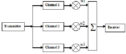
In telecommunications, maximal-ratio combining [9] is a method of diversity combining in which: (a) the signals from each channel are added together,(b) the gain of each channel is made proportional to the rms signal level and inversely proportional to the mean square noise level in that channel.(c) different proportionality constants are used for each channel. It is also known as ratio-squared combining and predetection combining.
Maximal-ratio-combining is the optimum combiner for
independent AWGN channels. In this method, the diversity branches are weighted for maximum SNR as can be seen in Figure 5 [9].
The Combiner output is given by
𝑦 𝑡 = 𝑀−1𝑖=0 𝑤𝑖𝑟𝑖 𝑡 ………... (12)
The SNR of the combined signal is
𝛤 =
𝑀 −1𝑖=0 𝐴𝑖2𝐸𝑏𝑁0 ….……… (13)
5.2 Equal-Gain Combining Diversity (EGC
)Various techniques are known to combine the signals from multiple diversity branches. In Equal Gain Combining,[10] each signal branch weighted with the same factor, irrespective of the signal amplitude. However, co-phasing of all signals is needed to avoid signal cancellation. In figure 5 each branch signal is rotated by 𝑒−𝑗 𝜃𝑖, all branch signals are then added.
The Combiner output is given by
𝑦 𝑡 = 𝑒−𝑗 𝜃𝑖𝑟 𝑖 𝑡 𝑀−1
𝑖=0 ……….… (14)
The SNR of the combined signal is
Γ = 𝑀 −1𝑖=0 𝐴𝑖 2
𝐸𝑏
𝑀𝑁0
...……… (15)
VI.
R
ESULTSIf we set the simulation environment for the OFDM based wireless modulation, then we get the variable performance for equalizers as well as for diversity techniques.
The following results have been obtained with the considered combinations.
Fig. 1.
Fig. 2.
Fig. 3.
0 3 6 9 12 15 18 21 24 27 30
10-0.15 10-0.13 10-0.11 10-0.09 10-0.07 10-0.05 10-0.03
SNR in dB
B
it
E
rr
o
r Ra
te
o
f
E
GC
BER with 'LS', 'MRC', 'ZF', 'EGC' with 512 Subchannels, 32 QAM and 1000 iterations
LS MRC ZF EGC
0 3 6 9 12 15 18 21 24 27 30 10-0.13
10-0.11 10-0.09
10-0.07
10-0.05
10-0.03
SNR in dB
B
it
E
rr
o
r Ra
te
o
f
E
GC
BER with 'LS', 'MRC', 'ZF', 'EGC' with 256 Subchannels, 32 QAM and 1000 Iterations
LS MRC ZF EGC
0 3 6 9 12 15 18 21 24 27 30 10-0.16
10-0.14
10-0.12 10-0.1 10-0.08
10-0.06
10-0.04 10-0.02
SNR in dB
B
it
E
rr
o
r Ra
te
o
f
E
GC
BER with 'LS', 'MRC', 'ZF', 'EGC' with 1024 subchannels, 32 QAM and 3000 iterations
366 Copyright © 2012 IJECCE, All right reserved
Fig. 4.
Fig. 5.
Fig. 6.
Fig. 7.
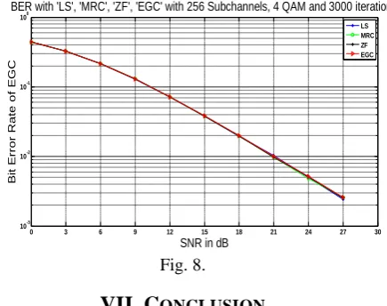
Fig. 8.
VII.
C
ONCLUSIONIn this paper we have considered the maximum number equals 3000. We have also considered varying number of subchannels. The wireless communication without the channel estimation results in high errors. Therefore channel estimation is important to know the parameters of the channel and also to get the knowledge of affecting parameters. Without the channel estimation we can not find the proper knowledge of the channel and impairments.
If we look at the simulation result with 1024 subchannels and 1000 iterations, we find that the BER curve is becoming linear and therefore with high number of subcarriers and with 1000 iterations we get more better results compared to 256 and 512 subchannel conditions. Figure no.7, shows the effect of the
different equalizers and diversity techniques with the 2000 iterations and 1024 subchannels. Here we find the results in the range of 0.1 to 0.001. But not a good difference is seen here.
One thing is clear here that with lower order QAM modulation techniques results are not much comparative, but results in bunching like the optimum performers.
Only the change between performances can be seen with lower number of subcarriers and with 1000 iterations.
Therefore we conclude with this assumption that with more number of iterations and with the higher number of subchannels results can be improved but at the cast of high simulation time. Finally with 1000 iterations we have better performance of used algorithms and MRC is very much able to show expected results and with less complexity in achieving the better BER performance.
A
CKNOWLEDGMENTForemost, I would like to express my sincere gratitude to my advisor Prof. Ravi Mohan for the continuous support of my M.Tech study and research, for his patience, motivation, enthusiasm, and immense knowledge. His guidance helped me in all the time of research and writing of this thesis. I could not have imagined having a better advisor and mentor for my M.Tech study.
Besides my advisor, I would like to thank Prof. L. D. Malviya for their encouragement, insightful comments,
0 3 6 9 12 15 18 21 24 27 30 10-0.04
10-0.03 10-0.02
SNR in dB
B it E rr o r Ra te o f E GC
BER with 'LS', 'MRC', 'ZF', 'EGC' with 64 subchannels, 32QAM and 1000 iterations
LS MRC ZF EGC
0 3 6 9 12 15 18 21 24 27 3030 10-0.38 10-0.36 10-0.34 10-0.32 10-0.3 10-0.28 10-0.26 10-0.24
SNR in dB
B it E rr o r Ra te o f E GC
BER with 'LS', 'MRC', 'ZF', 'EGC' with 64 Subchannels, 4 QAM, and 3000 iterations
LS MRC ZF EGC
0 3 6 9 12 15 18 21 24 27 30 10-0.38 10-0.36 10-0.34 10-0.32 10-0.3 10-0.28 10-0.26 10-0.24
SNR in dB
B it E rr o r Ra te o f E GC
BER with 'LS', 'MRC', 'ZF', 'EGC' with 64 subchannels, 4 QAM and 1000 iterations
LS MRC ZF EGC
0 3 6 9 12 15 18 21 24 27 30 10-3
10-2 10-1
100
SNR in dB
B it E rr o r Ra te o f E GC
BER with 'LS', 'MRC', 'ZF', 'EGC' with 1024 Subchannels, 4 QAM and 2000 iterations
LS MRC ZF EGC
0 3 6 9 12 15 18 21 24 27 30 10-3
10-2 10-1
100
SNR in dB
B it E rr o r Ra te o f E GC
BER with 'LS', 'MRC', 'ZF', 'EGC' with 256 Subchannels, 4 QAM and 3000 iterations
367 Copyright © 2012 IJECCE, All right reserved
and hard questions. Last but not the least, I would like to thank my family & my friends for supporting me spiritually throughout my life.
R
EFERENCES[1] B. Yang.K.B. Letaief,R.S. Cheng, Z. Cao,“ Channel estimation for OFDM transmission in multipath fading channels based on parametric channel modeling,“ IEEE Trans. Communication, Vol. 49, no. 3, pp 467-478, march 2001.
[2] Y.LI, J.H. Wintess, and N.R. Sollenberger “MIMO-OFDM for wireless communications, Signal detection with enhanced channel estimation,”IEEE Trans. Communication, Vol. 50, no. 9, sept. 2002, pp. 1471–1477.
[3] Yushi Shen and Ed Martine Z, “Channel estimation in OFDM systems’” January 2006.
[4] www.google.co.in
[5] B. P. Lathi, “Modern Digital and analog Communication systems“.
[6] Theodore S. Rappaport, “Wireless Communication, Principles and practice,” 2nd Edition.
[7] John G. Proakis and Masoud Salehi, “Digital Communications, 5th edition
[8] Hafeth Hourani, “An overview of diversity techniques in wireless communication systems,” Helsinki University of technology.
[9] A. Shah and A.M. Haimovich, “Performance analysis of maximal ratio combining and comparison with optimum combining for mobile radio communications with cochannel interference”, IEEE Trans. Veh. Technol., vol. 49, pp. 1454-1463, Jul 2000.
[10] Y. Song, S. D. Blostein and J. Cheng, “Exact Outage Probability for Equal Gain Combining EGC With Cochannel Interference in Rayleigh Fading,” IEEE Trans. Wireless Commun., vol. 2, no. 5, pp. 865-870, Sept. 2003.
A
UTHOR’
SP
ROFILEDeepmala Singh Parihar
DOB - 3rd Oct. 1984 at Satna