171
This work is licensed under Creative Commons Attribution 4.0 International License.
Design, Management and Key Success Factors of an Offshore Cathodic
Protection System for Corrosion Control
Shobhendu Prabhakar1 and Gaurav Goswami2 1Project Quality Manager, TechnipFMC, Houston, TX, USA
2
QA/QC Specialist, Chevron, NIGERIA
1Corresponding Author: [email protected]
ABSTRACT
Corrosion is a very prevalent issue for offshore operations in the oil and gas industry. If the corrosion issues are not addressed adequately, these may lead to quality failures, safety incidents, compromise to asset integrity and high inspection costs. This research paper discusses and analyzes corrosion types, corrosion threats, mechanisms to protect against corrosion, design and management of cathodic protection system, and key success factors for a cathodic protection system for an offshore oil and gas production system.
Keywords— Corrosion, Corrosion Threats, Corrosion Control, Cathodic Protection System, Offshore oil and Gas Production System
I.
INTRODUCTION
Corrosion, a phenomenon, in the Offshore structures, rigs, and platforms, can not only cause significant losses for the oil and gas companies but it can also lead to equipment failure and on-site accidents.
There are multiple ways to define corrosion from narrow definitions that usually cover only the specific form of corrosion to broad definitions that cover many forms of deterioration [1]. Origin of corrosion comes from a Latin word, corrodere, which means ‘to gnaw to pieces’. In
simplistic terms, corrosion can be defined as a chemical reaction between a metal and its environment which causes a deterioration of the material and its properties [1]. It is important to understand that the extent of corrosion depends on two factors: a) the material and b) the environment to which the material is exposed to. Both of these factors are dependent on each other and are not mutually exclusive [1]. In the context of Offshore structures, rigs and platforms, corrosion is an electrochemical process. In this electrochemical process, the electrolyte is the seawater, and due to different potentials between different parts of the steel structure, the metal ions move from the surface of the structure and diffuse into the electrolyte solution. These metal ions react with oxide and hydroxide ions to form corrosion products. The presence of dissolved oxygen also becomes a key concern since dissolved oxygen is greater
near the water’s surface. Because of this proximity, the dissolved oxygen imposes a higher corrosive overpotential in the vicinity of this region in comparison to the metal further under the surface. As a result of this process, pits can form at the metal surface of the platform. Corrosion within these pits as well as within crevices [such as the structure’s joints or imperfections in weldings] occurs as an irregular corrosion on the steel surface of the platform. Over a period, the increased stresses caused by the pits, crevices, and other structural anomalies [due to the electrochemical reactions] lead to fractures and breaks within the structure. The rate of corrosion depends on the microstructure of the metal itself [2].
According to NACE International, the Worldwide Corrosion Authority, the total annual cost of corrosion in the oil and gas production industry is estimated to be $1.372 billion, broken down into $589 million in surface pipeline and facility costs, $463 million annually in downhole tubing expenses, and another $320 million in capital expenditures related to corrosion [3]. In the light of such massive costs, and safety incidents [4] caused due to corrosion, it becomes extremely important to control and prevent corrosion.
The focus of this research paper is to discuss and analyze key components to design and manage an effective and efficient Offshore Cathodic Protection System (OCPS), an OCPS that can minimize losses and safety incidents due to corrosion of the offshore oil and gas production system components [including but not limited to subsea trees, jumpers, flowlines, pipeline end terminals (PLETs), pipeline end manifolds (PLEMs), in-line sleds (ILSs), jackets, platforms, risers, manifolds, export pipelines, and shore crossing pipelines].
II.
FORMS OF CORROSION
Corrosion can be prevalent in different types of forms as detailed below.
172
This work is licensed under Creative Commons Attribution 4.0 International License.
Figure 1: General CorrosionLocalized Corrosion is a type of corrosion where there is more loss of metal in a localized area of the surface in comparison to the rest of the metal surface area. In other words, the corrosion attack is more intense at one or more localized sites on the metal surface while the rest of the metal surface sees less corrosion [5]. This type of corrosion is sometimes also called Pitting. A representative of localized corrosion or pitting is depicted below in Fig.2.
Figure 2: Localized Corrosion
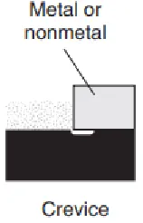
Crevice Corrosion is a local corrosion due to stagnant solution at the microenvironmental level. Typically, these stagnant microenvironments inclined to happen in the crevices (or gaps) between two metals or a metal and non-metal [6, 7]. Fig. 3 represents a typical crevice corrosion.
Figure 3: Crevice Corrosion
Galvanic Corrosion is defined as a corrosion induced when two (or more) dissimilar metals are joined in a corrosive electrolyte. Typically, it happens when two (or more) dissimilar metals are brought into electrical contact under water. The reason behind this corrosion is that these two dissimilar metals form a galvanic couple. In the galvanic couple, one metal acts as an anode (i.e. active) corroding faster than it would by itself and the other metal acts as a cathode (i.e. noble) corroding slower than it would by itself [8]. Fig. 4 illustrates an example of a galvanic corrosion.
Figure 4: Galvanic Corrosion
Erosion Corrosion is a type of corrosion in metals where material degrades due to mechanical wear by solid particles, liquid or the combination of both processes interacts with corrosion due to dissolution or surface oxidation [9]. A typical representation of Erosion Corrosion is given in Fig. 5.
Figure 5: Erosion Corrosion
Cavitation is a form of corrosion due to the implosion of gas bubbles on a metallic surface. Typically, it is caused by sudden/abrupt variations in pressure related to the hydrodynamic parameters of the fluids [10]. Fig. 6 represents a typical cavitation corrosion.
Figure 6: Cavitation Corrosion
173
This work is licensed under Creative Commons Attribution 4.0 International License.
Figure 7: FrettingDe-alloying [or Selective Leaching] is a corrosion in which there is a selective removal of one element from an alloy [13]. In this type of corrosion, there is a deterioration of essential properties of the alloy [14]. Fig. 8 provides a representation of de-alloying.
Figure 8: Dealloying
Environmental Cracking is a corrosion which is caused by a combination of conditions that can result in one of the following forms of corrosion [15]:
Stress Corrosion Cracking [SCC] is the
cracking/corrosion caused due to combined influence of tensile stress and a corrosive environment [16]. SCC is also a term frequently used to describe any type of environmentally induced or assisted crack propagation [17]. Typical representation of SCC is represented in Fig. 9 below.
Figure 9: Stress Corrosion Cracking
Corrosion Fatigue is caused by combined action of an alternating or cyclic stress and a corrosive environment. Due to the fatigue, the protective passive film is typically
ruptured causing acceleration of the corrosion [18]. Fig. 10 below illustrates a typical corrosion fatigue.
Figure 10: Corrosion Fatigue
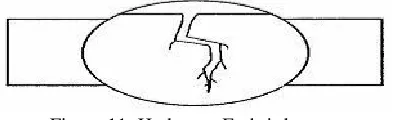
Hydrogen Embrittlement is the loss of ductility and reduction of load bearing capability in the metal due to the absorption of hydrogen atoms or molecules by the metal. Hydrogen embrittlement results in component crack and fracture at stresses less than the yield strength of the metal [19]. A typical Hydrogen Embrittlement is depicted in Fig. 11 below.
Figure 11: Hydrogen Embrittlement
High Temperature Corrosion is a type of corrosion which does not require a liquid electrolyte to be present. In this type of corrosion, metal reacts directly with gaseous atoms present in the atmosphere instead of ions in the solution [20, 21]. This type of corrosion damage is also called Dry Corrosion or Scaling.
III.
THREATS OF CORROSION IN AN
OFFSHORE OIL AND GAS
ENVIRONMENT
Following are typical threats of corrosion in an offshore oil and gas environment.
CO2 Corrosion: Historically, corrosion due to Carbon Di Oxide (CO2)has been an issue in the oil and gas production systems. When CO2 comes in contact with water, it forms carbonic acid, which typically promotes an electrochemical reason with steel causing the corrosion. Extent of CO2 corrosion depends on various factors such a) temperature, b) composition of aqueous stream, c) flow condition, d) increase in pH value and e) characteristics of the metal. CO2 corrosion is the most prevalent form of corrosion in the oil and gas production [22]. It is sometimes also called Sweet Corrosion.
174
This work is licensed under Creative Commons Attribution 4.0 International License.
Typical forms of this type of corrosion are uniform andpitting [22].
Oxygen Corrosion: Oxygen being a strong oxidant, it
reacts with metals very fast. Oxygen accelerates the anodic destruction of the metal. Additionally, with Oxygen’s presence, the corrosive effects of the acid gases such as CO2 and H2S are magnified. Uniform corrosion and pitting are most common forms of Oxygen Corrosion [22]. Crevice Corrosion: Since there are numerous opportunities for narrow crevices in the oil and gas environment, this type of localized corrosion can occur. Concentration differences of corrodents over a metal surface is primary cause of crevice corrosion [22].
Erosion Corrosion: In this type of corrosion, there is a continuous removal of the passive layer of corrosion products from the wall of the pipe, which causes increase in the corrosion reaction rate. This corrosion typically occurs at the places where there is a high turbulence flow regime. Fluid flow rate and density of solids present in the fluid impact the extent of corrosion [22].
Micro-biologically Induced Corrosion: Bacterial
activities are primary cause of this type of corrosion in the offshore environment. CO2, H2S and organic acids produced by bacteria causes pipelines to corrode [22]. Stress Corrosion Cracking: It is a localized corrosion that produces cracks in the metals by corrodent(s) and tensile stress acting together. This type of corrosion is prevalent in the offshore pipelines [22].
IV.
MECHANISMS TO PROTECT FROM
CORROSION IN AN OFFSHORE
ENVIRONMENT
Corrosion challenges in the offshore environment are dynamic. Characteristics of fluid and extent of exposure to the surroundings change over time. Therefore, coming up with corrosion control and mitigation mechanisms become even more challenging. Though challenging, the effective management of corrosion is a MUST in the offshore oil and gas industry. If corrosion is not controlled and managed effectively, it can lead to compromising asset integrity, equipment failure, high inspection costs and safety incidents. Typical methods to mitigate corrosion in the offshore environment and in the offshore oil and gas production system components [including but not limited to subsea trees, jumpers, flowlines, pipeline end terminals (PLETs), pipeline end manifolds (PLEMs), in-line sleds (ILSs), jackets, platforms, risers, manifolds, export pipelines, and shore crossing pipelines] are classified as below:
Material Selection and Designing for Corrosion Control
Chemical Treating
Protective Coatings and Linings Cathodic Protection System Process Control
Preventive Maintenance
Since the focus of this research paper is the design and management of an Offshore Cathodic Protection System, let us dive into it in the following sections.
V.
DESIGN AND MANAGEMENT OF
CATHODIC PROTECTION SYSTEM FOR
AN OFFSHORE OIL AND GAS
PRODUCTION SYSTEM
In 1820’s, Sir Humphrey Davy first time practically used the cathodic protection technique to mitigate the corrosion of copper sheeting on naval vessels. Since then, cathodic protection has been in widespread use in the oil and gas industry [23]. There are two types of cathodic protection systems namely a) Impressed Current Cathodic Protection systems and b) Sacrificial Anode Cathodic Protection Systems are typically used in the offshore oil and gas industry. The selection of cathodic protection system depends on many factors including but not limited to:
a) Platform type
b) Design code requirements c) Material and Coating types d) Designed life
e) Components (e.g. risers, flowlines, and mooring systems etc.) attached to the Offshore oil and gas production system
f) Life cycle cost and;
g) Pipeline installation methods.
Cathodic protection systems for various components of an offshore oil and gas production system are typically designed by different contractors/sub-contractors due to a) the complexity involved in the offshore oil and gas production system and b) project schedule as well as cost constraints [24]. Because there are multiple contractors/subcontractors involved, it is critical to have an integrated design approach when designing the individual cathodic protection systems so that they all together operate in harmony within the offshore oil and gas protection system.
Cathodic Protection Management Program: One of the
175
This work is licensed under Creative Commons Attribution 4.0 International License.
Clearly define all cathodic protection requirementsin the design, installation and maintenance of individual cathodic protection systems
Material selection guidelines
Parameters to be followed by various contractors when they are designing their part of the overall cathodic protection system
Mitigate and minimize interface issues that may arise in different phases of the project lifecycle Act as an owner’s manual that documents all
aspects of the cathodic protection system
Cathodic Protection Plan Diagram: Defining all the
cathodic protection scopes and alignment of system cathodic protection design requirements can be achieved by developing an overall project cathodic protection plan diagram and detailed diagrams for individual cathodic protection scopes within the oil and gas production system [24]. Purpose of the cathodic protection plan is:
To provide a 3D interpretation of all the equipment and components that comprise the entire offshore project
To provide clear and concise picture of corrosion protection design and materials requirements To serve as a dynamic tool is continuously updated
with data collected during different phases (design, fabrication, installation and operations) of the cathodic protection system during the entire project life cycle
Components of a cathodic protection plan diagram: Anode specifications
Anode drawings
Anode as-built dossier (manufacturing data book) Anode installation procedure
Cathodic protection design reports
Cathodic protection commissioning reports Cathodic protection survey reports for the surveys
conducted during operational phase.
VI. KEY SUCCESS FACTORS TO
CONSIDER IN DESIGN AND
MANAGEMENT OF AN OFFSHORE
CATHODIC PROTECTION SYSTEM
As explained in section V above, the design of the cathodic protection system for offshore oil and gas production system is complex. This complexity, often, leads to interface, operations, quality and safety risks. To mitigate the risks and ensure the success of the cathodic protection system, following factors shall be considered when designing and managing a cathodic protection system for an oil and gas production system.
a) Cathodic Protection Management program MUST
address:
Selection of Anode Materials
Manufacturing and installation of anodes Due diligence in selecting design inputs
Identification and mitigation of compatibility risks between cathodic protection and component materials
Interface between Induced Current Cathodic Protection and Sacrificial Anode Cathodic Protection
Installation methods and operation philosophy Requirements for the cathodic protection
documentation to be provided by relevant parties. b) Change Management: Cathodic Protection system
design shall be re-evaluated in the event of any changes (including but not limited to anode size, weight, distribution, and installation) to the cathodic protection design. This re-evaluation will ensure a quality and safe design.
c) Project specific requirements MUST be clearly defined before designing the Cathodic Protection system to avoid:
Inconsistencies and incompatibilities between different design guidelines
Increased materials cost due to over conservatism in design
Coating concerns
d) A qualified and experienced Cathodic Protection Lead/Engineer MUST be assigned to the project. This will ensure:
Key decisions about project cathodic protection are made timely
Collaboration among all parties/stakeholders (oil and gas operator, EPCI [Engineering, Procurement, Construction and Installation Contractor(s), and anode manufacturer(s) involved on the project
Effective management of any required modifications to cathodic protection design arising from updates to operating conditions or installation requirements
e)
Use of an electronic information management system (as opposed to traditional systems) to store all required data for the cathodic protection management program. This will ensure efficient access and retrieval to the relevant stakeholders and at the same time minimizing duplication and errors.176
This work is licensed under Creative Commons Attribution 4.0 International License.
VII. SCOPE OF FUTURE RESEARCH
In the future, the authors of this research paper would like to analyze other methods [such as Material selection and designing for corrosion control, chemical treating, protective coatings and linings, process control and preventive maintenance] to protect corrosion in the offshore environment and an oil and gas production system.
Authors would also like to research quality assurance and quality control activities to be performed in design, management and maintenance of cathodic protection system to protect and control corrosion in offshore oil and gas production systems [and its components].
VIII. CONCLUSION
Corrosion, in its basic form, is the deterioration of the metal resulting from an electrochemical reaction with its surrounding atmosphere/environment. With the presence of salt water, O2, CO2, H2S and micro biologically induced bacteria along with numerous opportunities for crevices, the offshore oil and gas production system as a whole and its individual components [including but not limited to subsea trees, jumpers, flowlines, pipeline end terminals (PLETs), pipeline end manifolds (PLEMs), in-line sleds (ILSs), jackets, platforms, risers, manifolds, export pipelines, and shore crossing pipelines] are even more susceptible to corrosion. In the light of the total annual cost of corrosion in the oil and gas production industry estimated at approximately $1.372 billion, it is critical to design and manage cathodic protection system along with implementation of other corrosion protection mechanisms in the most effective manner. In this research paper, the authors discussed and analyzed what makes a cathodic protection system for the offshore environment and offshore oil and gas production system. By implementing a robust, effective and efficient cathodic protection system, the companies in the oil and gas industry will not only see cost savings but will also observe reduction in the quality failures and safety incidents due to the corrosion.
Disclaimer:
This paper does not represent any TechnipFMC position, and it is in no way related to TechnipFMC.
This paper does not represent any Chevron position, and it is in no way related to Chevron.
REFERENCES
[1] The effects and economic impact of corrosion. (2000).
ASM International: Corrosion: Understanding the Basics (#06681G). Available at:
https://www.asminternational.org/documents/10192/184977 0/06691G_Chapter_1.pdf
.
[2] Brianne Christopher. (2015). Corrosion in oil platforms. Available at: https://www.comsol.com/blogs/corrosion-in-oil-platforms/.
[3] NACE International. (2018). Oil and gas production. Available at: https://www.nace.org/resources/industries-nace-serves/oil-gas-production.
[4] Global CCS Institute. (2018). General corrosion. Available at:
https://hub.globalccsinstitute.com/publications/corrosion-and-materials-selection-ccs-systems/64-general-corrosion. [5] Localized corrosion. (2018). Available at: https://corrosion-doctors.org/Localized/Introduction.htm. [6] Crevice corrosion. (2018). Available at: https://www.corrosionclinic.com/types_of_corrosion/crevic e_corrosion.htm
.
[7] Crevice corrosion. 92018). Available at:
https://www.nace.org/resources/general-resources/corrosion-basics/group-1/crevice-corrosion. [8] Galvanic corrosion. (2018). Available at:
https://www.nace.org/resources/general-resources/corrosion-basics/group-1/galvanic-corrosion. [9] M. M. Stack et. Al. (2011). Models and mechanisms of erosion – Corrosion in metals in tribocorrosion of passive
metals and coatings. Available at:
https://www.sciencedirect.com/topics/materials-science/erosion-corrosion.
[10] The Multimedia Corrosion Guide. (2018). 7- Erosion
and cavitation corrosion. Available at:
https://www.cdcorrosion.com/mode_corrosion/corrosion_er osion_gb.htm.
[11] Fretting Corrosion. (2012). Science direct. Available at: https://www.sciencedirect.com/topics/materials-science/fretting-corrosion.
[12] Fretting corrosion. (2018). Available at:
https://www.nace.org/resources/general-resources/corrosion-basics/group-2/fretting-corrosion. [13] Dealloying (Selective leaching). (2018). Available at:
https://www.nace.org/resources/general-resources/corrosion-basics/group-2/dealloying.
[14] What does dealloying mean?. (2018). Available at: https://www.corrosionpedia.com/definition/360/dealloying
.
[15] Environmental cracking. (2018). Available at:177
This work is licensed under Creative Commons Attribution 4.0 International License.
[16] Stress corrosion cracking. (2019). Available at:
https://www.nace.org/resources/general- resources/corrosion-basics/group-3/stress-corrosion-cracking.
[17] R. H. Jones & R. E. Ricker. (1992). Mechanisms of
stress-corrosion cracking. Available at:
https://www.asminternational.org/documents/10192/184977
0/06355G_Sample.pdf/daf91547-a566-4f77-83a0-1fca83b87157.
[18] Corrosion fatigue. (2019). Available at:
https://www.nace.org/resources/general-resources/corrosion-basics/group-3/corrosion-fatigue. [19] Hydrogen embrittlement of steel. (2019). Available at:
https://www.imetllc.com/training-article/hydrogen-embrittlement-steel/.
[20] Pierre R. Roberge. (2017). Corrosion basics: High-
temperature corrosion. Available at:
http://www.materialsperformance.com/articles/corrosion- basics/2017/02/corrosion-basics-high-temperature-corrosion.
[21] R.C. John. (1999). Compilation and use of corrosion data for alloys in various high-temperature gases. Available at:
https://www.onepetro.org/conference-paper/NACE-99073. [22] Popoola, L.T., Grema, A.S., & Latinwo, G.K. et al. (2013). Corrosion problems during oil and gas production and its mitigation. International Journal of Industrial Chemistry. Available at:
https://link.springer.com/article/10.1186/2228-5547-4-35
.
[23] Hristo Ivanov. (2016). Corrosion protection systems in
offshore structures. Available at:
https://ideaexchange.uakron.edu/cgi/viewcontent.cgi?article =1314&context=honors_research_projects
.
[24] Xu, L.Y., Su, X., & Cheng, Y.F. (2013). Effect of alternating current on cathodic proetection on pipelines.