University of Huddersfield Repository
Lan, XiangqiThe Development of a Flexible Characterisation System for Surface Metrology
Original Citation
Lan, Xiangqi (2014) The Development of a Flexible Characterisation System for Surface Metrology. Doctoral thesis, University of Huddersfield.
This version is available at http://eprints.hud.ac.uk/id/eprint/20332/
The University Repository is a digital collection of the research output of the University, available on Open Access. Copyright and Moral Rights for the items on this site are retained by the individual author and/or other copyright owners. Users may access full items free of charge; copies of full text items generally can be reproduced, displayed or performed and given to third parties in any format or medium for personal research or study, educational or notforprofit purposes without prior permission or charge, provided:
• The authors, title and full bibliographic details is credited in any copy; • A hyperlink and/or URL is included for the original metadata page; and • The content is not changed in any way.
For more information, including our policy and submission procedure, please contact the Repository Team at: [email protected].
THE DEVELOPMENT OF A FLEXIBLE CHARACTERISATION
SYSTEM FOR SURFACE METROLOGY
Xiangqi Lan
A thesis submitted to the University of Huddersfield
in partial fulfilment of the requirements for
the degree of Doctor of Philosophy
School of Computing and Engineering
University of Huddersfield
1
Abstract
Surface texture and its measurement are becoming more and more increasingly important in the field of high precision engineering and nano-technology. It is a significant and efficient way to predict the functional performance of an engineering product by characterising its surface. As the extraction and evaluation of surfaces features not only relies on analysis algorithms but also measurement techniques, most of surface characterisation software systems are embedded in the measurement instruments. At present, even though a series of Geometrical Product Specification (GPS) standards are released to guide the procedure of surface characterisation, there are no software systems give a fully support of them. As a consequence, evaluation results from different systems are incomparable, even worse, conflict with each other.
Surface characterisation system needs to be updated constantly with the emergence of new algorithms and methods. However, the lack of good extensibility, reusability and maintainability is a serious obstacle to the innovation of existing surface characterisation systems. As functional modules in current surface characterisation systems are tightly coupled together, it is not conducive to the reuse of function modules and innovation of overall system. A lot of redundant and duplicate works have been raised in either enhancing present characterisation systems or building a new characterisation system.
To improve the reusability of function modules and facilitate system extension, this research aims to establish a flexible surface characterisation system with an open architecture. By employing component based development technologies, the overall characterisation system is constructed by gluing various functional components together instead of being created from scratch. Each analysis algorithm or method is implemented as an independent functional component, which is separated from the system framework. And also it can be easily reused by other characterisation systems as an executable chunk. Any system functional components can be developed or maintained independently by different organisation as long as they comply with predefined protocols (interfaces).
2
Acknowledgements
First of all, I would like to express my sincere gratitude to my supervisor, Prof. Xiangqian Jiang for setting up an appropriate research subject. She offers her unreserved help and guidance, and leads me to finish my thesis. Her words can always inspire me and bring me to a higher level of thinking. Many thanks also give to her for kindly support, advice and encouragement.
Great appreciation also goes to my second supervisor, Prof. Liam Blunt, for his exceptional support and guidance throughout my thesis. Without his kind and patient instruction, it is impossible for me to finish this thesis. He gave lots of time helping me to improve my academic writing and the capability of carrying out professional researches.
I am also indebted to Prof. Paul Scott, Dr. Shaojun Xiao and Dr. Feng Xie for their valuable guidance and suggestions. Special thanks to Dr. Wenhan Zeng and Dr. Haydn Martin. They squeeze time from their busy schedule to help me correct my thesis.
I would like to show my appreciation to Taylor Hobson Ltd. for the support and sponsorship of my studies, and I am also grateful to the EPSRC Centre for Innovative Manufacturing in Advanced Metrology, the Centre for Precision (CPT) and the School of Computing and Engineering of the University of Huddersfield for providing me the opportunity and facilities to carry out this project.
Sincere thanks to my colleagues for sharing their insights, many useful discussions and valuable suggestions, and my friends for their kindly support and encouragements.
3
Contents
Abstract ... 1
Acknowledgements ... 2
List of Figures ... 7
List of Tables ... 9
List of Acronyms ... 10
Chapter 1 Introduction ... 11
1.1 Background ... 11
1.2 Aim and Objectives ... 16
1.3 Approach ... 19
1.4 Thesis Structure ... 21
Chapter 2 Surface Characterisation Techniques ... 24
2.1 Introduction ... 24
2.2 Surface Verification Operator ... 24
2.3 Surface Measurement ... 32
2.3.1 Stylus Methods ... 32
2.3.2 Optical Methods ... 35
2.3.3 Other Methods ... 36
2.3.4 Range and Resolution ... 37
2.4 Fitting Techniques ... 38
2.4.1 Least Squares fitting ... 39
2.4.2 Profile fitting ... 40
2.4.3 Areal fitting ... 42
2.5 Filtering Techniques ... 44
2.5.1 The Process of Filtering ... 45
2.5.2 Filtering Methods ... 47
2.6 Parameterisation ... 49
2.6.1 Statistical Methods ... 50
2.6.2 Geometrical Methods ... 52
2.7 Summary ... 53
Chapter 3 Design and Implementation of Flexible System Architecture ... 54
4
3.2 Component-Based Development ... 56
3.2.1 Component ... 56
3.2.2 Component-Based Software Development ... 57
3.2.3 Current Technology for Component-Based Architecture ... 58
3.2.4 Advantages of Component-Based Development ... 60
3.3 System Architecture Design ... 60
3.3.1 Separation of Analysis Functions and System Framework ... 60
3.3.2 Integrative Structure ... 61
3.3.3 Semi-detached Structure ... 62
3.3.4 Flexible Structure ... 63
3.3.5 Proposed Surface Characterisation System Architecture ... 64
3.4 Surfstand System Functional Component Categorisation ... 69
3.4.1 Data Access Component ... 69
3.4.2 Data Processing Component ... 70
3.4.3 Data Display Component ... 71
3.5 System Development Life Cycle ... 73
3.5.1 Waterfall Model ... 73
3.5.2 Incremental Model ... 75
3.5.3 Spiral Model ... 76
3.5.4 Development Model of SurfStand ... 78
3.6 Summary ... 81
Chapter 4 Implementation of Data Access Components ... 82
4.1 Conventional Surface Data File Format ... 82
4.2 Component Design ... 85
4.2.1 Surface Data Structure Design for the Proposed Surface Characterisation System 85 4.2.2 Surface Data Class Design for the Proposed Surface Characterisation System .... 89
4.2.3 Interface Design for the Data Access Components ... 90
4.3 Standard Surface Data Format: SDF ... 91
4.3.1 SDF File Format ... 92
4.3.2 Interface Implementation ... 96
5
Chapter 5 Design and Implementation of Data Process Components of the Developed System 98
5.1 Categorisation of Data Process Components ... 98
5.2 Component Interface Design of the Proposed System ... 103
5.2.1 Interface of Verification Operations ... 103
5.2.2 Interface for All Data Process Components ... 106
5.2.3 Interface for Subtypes of Data Process Components ... 108
5.3 Case Studies: Geometrical Analysis Component ... 109
5.3.1 Surface Segmentation ... 110
5.3.2 Boundary curve approximation ... 111
5.3.3 Geometrical features construction ... 114
5.3.4 Interface Implementation for Geometrical Analysis Component ... 116
5.4 Summary ... 118
Chapter 6 Implementation of Surface Visualisation Components ... 119
6.1 Computer Graphics ... 119
6.2 Computer Graphics Programming―OpenGL ... 121
6.2.1 Modelling ... 121
6.2.2 Transformation ... 122
6.2.3 Colour ... 125
6.2.4 Lighting ... 125
6.2.5 Other Functions of OpenGL ... 126
6.3 Component Interface Design ... 126
6.4 Three-Dimensional Display Component of the developed Surface Characterisation System 127 6.4.1 Coordinate System ... 127
6.4.2 Modelling ... 128
6.4.3 Render ... 129
6.4.4 Lighting and Object Materials ... 130
6.4.5 Interface Implementation ... 131
6.5 Summary ... 132
Chapter 7 Test and Evaluation of the Proposed Surface Characterisation System ... 133
7.1 Introduction ... 133
6
7.2.1 Test Case 1: SDF File Component ... 134
7.2.2 Test Case 2: 3D display component ... 135
7.3 Integration Tests ... 138
7.3.1 Test Case 1: SUR File Component ... 139
7.3.2 Test Case 2: Levelling Component ... 141
7.3.3 Test case 3: Topview component ... 142
7.4 System Tests ... 143
7.4.1 Test Case 1 Components Configuration ... 143
7.4.2 Test Case 2: Compound Command Test ... 144
7.5 Comparison ... 147
7.6 Summary ... 148
Chapter 8 Conclusions and Future Work ... 150
8.1 Summary ... 150
8.2 Contribution to Knowledge ... 152
8.2.1 Standardisation Analysis ... 152
8.2.2 Function Modularisation ... 153
8.2.3 System Flexibility ... 154
8.3 Future Work ... 155
References ... 157
Appendixes ... 163
A Critical Code Fragments of SurfStand SDK ... 163
B Code Fragments for the Connection between the Framework and Components ... 166
C Code Fragments for Surface Data Definition ... 168
D Definition of Command Interface: ISSCommand. ... 170
E Code Fragments for Method ModifyArgument of Feature Parameters Component ... 171
F Interface Definitions for the Three Subtypes of Data Process Components ... 172
7
List of Figures
Figure 1.1: Thesis structure diagram. ... 22
Figure 2.1: Comparison of Design Intent and Verification of manufactured workpiece. ... 25
Figure 2.2: Standard surface verification operator [2]. ... 28
Figure 2.3: F-operator—first order polynomial fitting. ... 29
Figure 2.4: L-filter—Gaussian regression filtering. ... 30
Figure 2.5: Calculation results of standard surface areal parameters. ... 31
Figure 2.6: The stylus principle. ... 33
Figure 2.7: Two types of stylus―Cone and Pyramid [51]. ... 34
Figure 2.8: Stylus slope effect. ... 34
Figure 2.9: Path of light in Michelson interferometer [56]. ... 36
Figure 2.10: Amplitude-wavelength plot of different instruments for surface measurements [61]. ... 38
Figure 2.11: Roughness, waviness and form of a profile [51]... 45
Figure 2.12: Filtering process in two domains―Space and Frequency [51]. ... 45
Figure 2.13: Cutoffs of surface filtering [51]. ... 46
Figure 3.1: A component with provided and required interfaces. ... 57
Figure 3.2: Integrative structure of software systems. ... 61
Figure 3.3: Semi-detached structure of software systems. ... 62
Figure 3.4: Flexible structure of software systems. ... 63
Figure 3.5: Data flow within a surface characterisation system. ... 65
Figure 3.6: Development hierarchy chart for SurfStand. ... 67
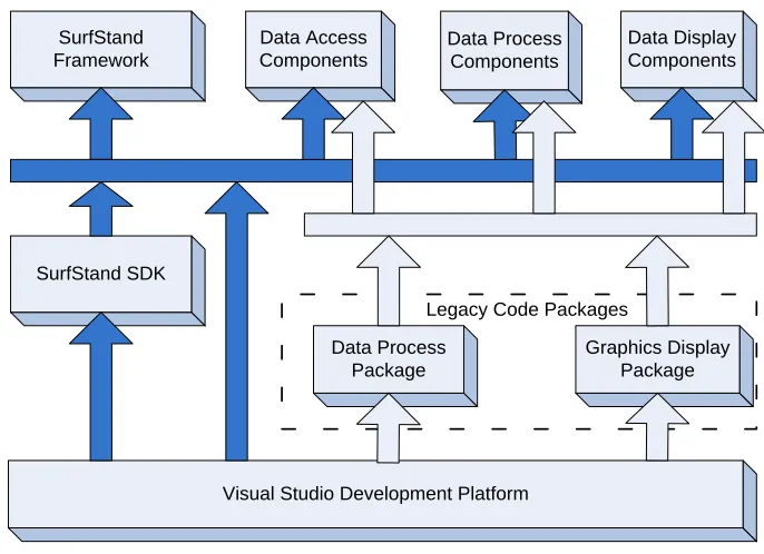
Figure 3.7: System architecture of SurfStand. ... 68
Figure 3.8: Function chart of Data Access Components. ... 70
Figure 3.9: Function chat of Data Process Components. ... 71
Figure 3.10: Data Display Components―3D Display Component... 72
Figure 3.11: Software development model―Waterfall model. ... 74
Figure 3.12: Software development model―Increment model. ... 76
Figure 3.13: Software development model―Spiral model. ... 76
Figure 4.1: Surface data pattern―Grid Data. ... 82
Figure 4.2: Data transfer between surface data file and internal data structure... 87
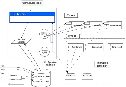
Figure 5.1: Example of Data Process Components―Type A. ... 100
Figure 5.2: Example of Data Process Components―Type B. ... 101
Figure 5.3: Example of Data Process Components―Type C. ... 102
Figure 5.4: Internal command class inheritance hierarchy diagram of developed system. ... 105
Figure 5.5: Relationship between commands and surface verification operators. ... 106
Figure 5.6:Relationship between commands and system functional components. ... 107
Figure 5.7: Class inheritance hierarchy diagram of data process components. ... 108
Figure 5.8 Demonstration of surface segmentation ... 111
Figure 5.9: One boundary curve of a geometrical feature. ... 112
Figure 5.10: Curvature of each point on the boundary curve. ... 113
Figure 5.11: Derivative of curvature along the boundary curve. ... 113
8
Figure 5.13: Characteristics list of geometrical features. ... 115
Figure 6.1: Computer graphics system principle. ... 119
Figure 6.2: Comparison of drawing a pentagon and five points... 122
Figure 6.3: Perspective viewing volume. ... 123
Figure 6.4: Orthographic viewing volume. ... 124
Figure 6.5: The geometry pipeline that achieves the coordinate transformation... 127
Figure 6.6: Default 3D model coordinate system of OpenGL... 128
Figure 6.7: 3D modelling of surface data. ... 129
Figure 6.8: Supported colour maps for surface render. ... 130
Figure 6.9: An example of materials rending―Brass. ... 131
Figure 7.1: A SDF file opened with the SDF file component. ... 134
Figure 7.2 The surface data that is saved with the SDF file component. ... 135
Figure 7.3: 3D display component loaded with ActiveX Control Test Container. ... 136
Figure 7.4: Surface data display with 3D mesh representation type. ... 136
Figure 7.5: Surface data rendered with hot colour map. ... 137
Figure 7.6: Surface data display with yellow rubber material. ... 138
Figure 7.7: Components Configuration dialog. ... 139
Figure 7.8: Open file dialog with supporting SDF and SUR file formats. ... 139
Figure 7.9: An example of surface data imported with SUR file component. ... 140
Figure 7.10: Open file dialog without supporting SUR file format. ... 140
Figure 7.11: The emerging levelling menu item after adding the levelling component. ... 141
Figure 7.12: The surface data that has been processed with levelling component. ... 142
Figure 7.13: The surface data that is displayed with Topview Component. ... 142
Figure 7.14:The surface data that is processed with Bearing curve analysis component. ... 144
Figure 7.15: Compound command creating dialog. ... 145
Figure 7.16: Subcommands modification of Test command. ... 145
Figure 7.17: Test command occurs in the Command setting dialog. ... 146
Figure 7.18: Parameters setting dialog of Gaussian regression filter. ... 146
Figure 7.19: The surface data that is processed with Test command. ... 147
Figure 8.1: Categorisation of system functional components. ... 151
9
List of Tables
Table 2.1: Common model functions for profile fitting. ... 40
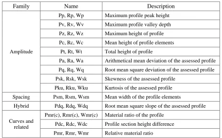
Table 2.2: Standard surface profile parameters. ... 50
Table 2.3: Standard surface areal parameters. ... 51
Table 2.4: Feature parameters defined in ISO 25178-2. ... 52
Table 4.1: Common file formats for surface data storage. ... 83
Table 4.2: Essential elements for every surface data file. ... 84
Table 4.3 Internal surface data structure elements. ... 86
Table 4.4: Arguments description of methods of interface SSFileIO. ... 91
Table 4.5: File header description of SDF surface file. ... 92
Table 4.6: Compression types list. ... 94
Table 4.7: Supported data types list of SDF file format. ... 95
Table 4.8: Checksum types list. ... 95
Table 5.1: Description of member variables and methods of interface ISSCommand. ... 104
Table 5.2: Description of arguments that occurs in SSAnalysisA, SSAnalysisB and SSAnalysisC. ... 109
Table 5.3: Combination patterns for common geometrical features. ... 115
Table 6.1: Property values for the brass material. ... 131
10
List of Acronyms
AFM Atomic Force Microscopy
API Application Programming Interface ARB OpenGL Architecture Review Board
ASCII American Standard Code for Information Interchange ATL Active Template Library
AXCTC ActiveX Control Test Container CBA Component-Based Architecture CBD Component-Based Development CCD Charge Couple Device
COM Component Object Model
CORBA Common Object Request Broker Architecture CPU Central Processing Unit
GPU Graphics Processing Unit IDL Interface Definition Language
ISO International Organization for Standardization JRMP Java Remote Method Protocol
JVM Java Virtual Machine
LS Least Squares
MC Minimum Circum scribed
MI Maximum Inscribed
MZ Minimum Zone
OMG Object Management Group ORB Object Request Broker RC Resistor-Capacitor
11
Chapter 1
Introduction
1.1
Background
The surface of an engineering workpiece can be thought of as the boundary between the
workpiece and the surrounding environment, and it is closely related to the functional
properties of the entire workpiece, such as tribological, thermal, electrical and optical
behaviour [1]. It has been revealed that 90% of all engineering workpiece failures in
practice are surface initiated due to corrosion, erosion, fretting wear, excessive abrasive
and so on [2]. Thus surface topographical features are important factors in determining
the satisfactory performance of a workpiece, and it is significant to understand the
functional properties of surfaces.
Surface metrology is the science of measuring geometrical features on surfaces. The
approach is to measure and characterise surface features in order to be able to understand
how the features are influenced by its history (e.g. manufacture, wear, fracture) and how
it influences its behaviour (e.g. adhesion, gloss, friction) [3]. From the occurrence which
can be traced back to the 1930s up to now, surface metrology has undergone a series of
huge paradigm shifts [4, 5]. Nowadays, it has become one of the fastest-growing areas of
engineering and quality management, and its study is becoming more and more
commonplace in industrial and research environments [6].
To understand and analyse surface features, surface measurement is a critical and
necessary procedure to acquire surface information from engineering workpieces. The
original way to measure surfaces was using the thumbnail and the eye, both of which
were subjective and effective only if used by an experienced practitioner. However, the
texture features of surfaces are too small to be assessed quantitatively by such a ―touch
and see‖ way [7]. Demand for quantitative results led to two parallel branches of
instrumentation; one following the tactile example of the nail, the other mimicking the
eye. Stylus profilometry and optical interferometry are two common techniques used in
carrying out surface metrology. In addition, there are also many other methods for
surface measurement such as using pneumatic technique, capacitance, ultrasound, and so
12
Normally, the aim of surface measurement methods is to acquire the surface information
effectively and accurately. There is no one method that can be adopted to measure all
kinds of surfaces. For a certain surface, the measurement method is decided by many
factors such as precision, scale, material, etc. However, measurement results consist of a
set of coordinates, which cannot be adopted to characterise the surface directly. A series
of data processing based on the measurement data is required to extract surface features.
With the benefit from modern digital technologies, e.g. Computer, which offers adequate
speed of operations and processing, the extraction and characterisation could be realised
by software systems. Nowadays, surface characterisation systems are mainly developed
by instrument companies, and they are usually deployed in surface measurement
instruments. For example, Talymap is such a software system which is primary
embedded in surface measurement instruments manufactured by Taylor Hobson [8]. With
these convenient and efficient systems, metrologists are able to carry out surface
characterisation and evaluation after measurements. Besides, some institutes also develop
their own surface characterisation system [8-10]. Although there are many surface
characterisation systems already, it is still necessary to implement flexible system
architecture. The reason will be elaborated from two different perspectives below.
From the point view of surface metrology, it is expected to get the same characterisation
and evaluation result for a particular measurement data. Conversely, there are always
large variations in the output results among different characterisation systems, which are
caused by a couple of reasons, such as ambiguous definitions, choices of analysis
methods and various implementations. ISO (International Organization for
Standardization) issued a series of characterisation standards which aim to standardise the
characterisation methods. For example, ISO 4287 specifies terms, definitions and
parameters for the determination of surface texture by profiling methods [11], while ISO
25178-2 specifies them by areal methods [12]. However, due to the mathematical
ambiguity of some definitions presented in these ISO standards, there is scope for
different interpretations of how to calculate the parameters. Consequently, software
engineers may design mathematically diverse algorithms to implement the definitions
[13]. That explains why it is hard to get the same result from different characterisation
13
the characterisation results as the communication information of a surface are
incomparable and untraceable, and it would be meaningless to compare analysis results,
which are derived from different characterisation systems.
In addition, surface characterisation and verification results are figured out by several
sequential steps of processing. According to GPS (Geometrical Product Specification)
standards, the whole procedure is recognised as an operator, while each step of
processing is thought of as one operation [2]. In other words, a surface verification
operator is usually composed of a set of sequential operations. Verification results are
closely related to the verification operator. At present, the realisation of surface
characterisation systems primary relies on operations instead of operators. Operators
cannot be provided by existing characterisation systems, and they are generated by
metrologists during the course of surface characterisation and verification. When
evaluating a particular surface, various verification operators are likely to be used for the
same surface by different metrologists, moreover, it is inevitable even though the
metrologists are the same person, therefore, evaluation results will be greatly affected by
the subjective determination. To reduce the influence caused by human factors, it is
essential to provide verification operators for a surface characterisation system.
From the perspective of software engineering, as aforementioned, there are a number of
characterisation systems developed by various companies or research institutes [8-10]. It
is well known that most of the functions of these characterisation systems are similar,
which should be implemented according to ISO standards. As a result, a great deal of
redundant and reduplicated work has been done, and each characterisation system has to
provide such a functional implementation. These characterisation systems suffer from a
couple of insufficient capabilities, which are elaborated from following aspects:
Reusability: Some basic and common functional modules are essential parts for
every surface characterisation system. Since they are developed to satisfy a
specific characterisation system, they cannot be reused by other systems. For one
thing, the development environment of a functional module, such as programming
language, tools and platform, is selected in accordance with the whole
14
another, functional modules are normally tightly coupled with the whole
characterisation system. They are not independent components and cannot
execute separately. When developing a new characterisation system, the
developer has to re-implement the similar and basic functional modules from
scratch instead of reusing existing ones, which will cost much time and effort [14].
Extensibility: Surface characterisation system is apt to be updated with the rapid
innovation of surface metrology techniques; evolving from profile to areal
characterisation, from stochastic to structured surface analysis and from simple
geometries to complex free form geometries. With the development of processing
and manufacturing technologies, novel characterisation techniques are expected to
satisfy new emerging requirements[15, 16]. Hence, not only the conventional
characterisation methods but also some state-of-the-art analysis algorithms and
techniques will be taken into account. However, it will cost too much to embed
those emerging techniques to the existing characterisation systems as developers
are supposed to have good knowledge of the characterisation system architecture.
Even worse, after the extension times and times again, the characterisation system
tends to become unstable and error-prone.
Maintainability: Maintenance is always a significant activity during the whole
life-cycle of modern software systems. It is inevitable to maintain surface
characterisation systems to keep their functionality in line with requirements and
ensure their availability [17]. For existing characterisation systems, code
modification is quite common during the procedure of maintenance as they are
tightly coupled. However, code modification can only be done assuming the
original code has been understood by maintainers. They also need to have
intimate knowledge of the system architecture, and that would cost too much time
and effort for them who have not participated in the design and development of
the system. Because of the different coding style, most software engineers prefer
writing the code themselves rather than reading others‘. With the incessant
modifications, surface characterisation systems will become increasingly
15
maintenance is that any modifications may cause the recompiling and rebuilding
of the whole system, and then redeployment on target computers, even if it is just
a slight modification [18].
Customisation: Generally, functions of surface characterisation systems are
determined by developers, which cannot be changed by end users. As they do not
provide any ―space‖ for users to reconfigure its functions, what users can do is
just to utilise existing analysis functional modules [19]. Sometimes, not all of the
functional modules provided by a characterisation system may be really useful for
some users, and they might want to use their own algorithm or idea to analyse
surfaces. However, it is impossible to embed users‘ algorithms to current
characterisation systems, and they have to develop a simplified version to practise
their algorithms. In other words, users will have to implement many other
functions which are not relevant to the algorithms themselves, such as file access
and data visualisation. That could be notoriously difficult and may lead to plenty
of irrelevant work for users.
As stated above, drawbacks of current surface characterisation systems have significant
effects not only on the realisation of standard surface characterisation process, but also
the renovation of themselves. Due to the fact they are implemented by various companies
and research institutes individually, the evaluation results from different characterisation
systems are not exactly the same, and what is worse is that some of them may be
contradicted with the others. According to the intention of GPS standards, the evaluation
result should be consistent no matter which characterisation system is adopted. Hence,
reducing ambiguous of GPS standard documents and affording relevant functional
modules would conduce to acquire comparable and traceable evaluation results.
Meanwhile, the low capability of functional module reuse, system extension,
maintenance, and user customisation is also a barrier of system evolution and
characterisation technology progress. To overcome aforementioned issues, it is essential
to develop a novel and flexible characterisation system for surface metrology. This
project sets out to realise such a surface characterisation system with the state-of-the-art
techniques of software engineering, and establish an open flexible architecture with the
16
In the realm of surface metrology, the crucial thing is how to acquire surface features and
evaluate surfaces by qualitative or quantitative analysis of these features. Currently, some
researchers have to be involved in the development of characterisation systems, and they
need a deep knowledge of the system architecture. Even worse, they will have to spend
substantial time to evolution and maintenance of the characterisation system [14], which
is not the primary work for a researcher of surface metrology. However, with the flexible
characterisation system, researchers can throw themselves into the research of
characterisation technologies rather than the implementation and maintenance of the
characterisation software system. They just realise their own analysis algorithms or
methods and build them as executable functional modules which can be embedded into
the flexible characterisation system.
1.2
Aim and Objectives
This thesis aims to establish a flexible software system for surface evaluation based on
the investigation and improvement on present surface characterisation techniques. The
most essential difference from current characterisation systems is that the designed
system will be constructed by various independent functional components instead of
being created as a standalone chunk. Namely, the entire system will be divided into one
system framework and a number of functional components: The system framework
mainly manages the interaction between the overall system and end user, event driven
and components management; Functional components, which are loosely coupled with
system framework, will be designed as an independent and executable block. Both the
system framework and functional components will be developed independently and then
can be seamless connected together at run-time.
It is envisaged that this project will contribute to the provision of a common
characterisation system for the researchers of surface metrology. Each user of the user
group can develop its own functional modules or outsource certain functional modules to
third party. The platform can provide a convenient method to share novel algorithms or
techniques and comparisons of analysis results will be realised easily. In order to achieve
17
1) Investigate the standard surface characterisation techniques. Surface parameters are widely accepted for evaluation of surface topography, and most
common parameters for profile and areal have been defined in ISO 4287 and ISO
25178-2 respectively. Generally, there a series of algorithmic operations needs to
be completed prior to calculating parameters, where the whole procedure for
evaluating surfaces can be recognised as a verification operator. To apply this
standard method to evaluate surfaces, it is therefore essential to develop and
understand the meaning of each parameter and the effect of each operation on the
resulting parametric outcome.
2) Design an open architecture for the software system. Open architecture means that the specifications of the architecture are public, and all the parts of the
architecture are loosely coupled. Specific functional analysis modules can be
added, removed or replace dynamically without affecting other parts of the
software system. Based on this open architecture, the ability to extend and
maintain the system no longer belongs to the system creators. Other developers
can also participate and share in the system innovation.
3) Categorise the analysis function modules. One functional module is an implementation of certain operation, and a series of sequenced operations are
composed to be an operator. In a characterisation system, there are many
functional modules. Usually, various functional modules need to be organised and
invoked in a different way. In order to reconfigure them dynamically, it is
necessary that they are discernible for the system framework. Thus, they ought to
be categorised by distinguishing their inherent attributes such as input and output.
4) Formulate the interaction protocols between functional modules and the system framework. As all analysis functional modules will be physically separated from the system framework, in this way the system architecture will not
become increasingly complex in nature. When evaluating surfaces, the standard
interaction protocols are prerequisites to connect functional modules and the
system framework together. These protocols specify how to carry out data
18
5) Develop the system framework and functional modules. As functional modules are independent parts and separated from others, they can be implemented without
taking into account others but only within predefined interaction protocols. The
system framework is an essential part for the entire software system, and it
functions as a container in which functional modules can be executed. Functional
modules are responsible for practical analysis activities, and they can be
reconfigured dynamically.
6) Construct the user customisation mechanism. The development of functional modules are not only realised by system developers but often by system end users.
Although developers can implement as many functional modules as they can, it is
still not enough for all users in that it sometimes requires specific analysis
algorithms for particular surface characterisation. Furthermore, the emergence of
novel analysis methods is ceaseless, and it is impossible for developers to cover
all of them. The customisation mechanism enables users to develop proper
algorithms or methods, for a certain surface evaluation cases, where the
developed functional module can be integrated into the software and can also be
directly distributed to other users without any modification.
The fundamental idea behind the software system is to separate functional modules from
the entire characterisation system absolutely. After achieving the above six objectives, a
novel flexible characterisation system can be established. Future end users can integrate
and customise new functional modules, yet the complexity of system architecture will not
increase when reconfiguring functional modules. In addition, establishing such a flexible
characterisation system is aimed at supplying a powerful software system to characterise
surface textures using multiple and customised functional modules. Every end user can
concentrate on individualised characterisation algorithms and methods, and then develop
his or her own functional modules and distribute them. In essence, the proposed system
will facilitate communications among different organisations and promote the deepening
19
1.3
Approach
During recent decades, with the advancement of computer technology and the consequent
software development is undergoing a huge paradigm shift: From the beginnings of
process-oriented approaches, through to object-oriented and later, to the current
aspect-oriented and component-aspect-oriented, software engineers have been working to simplify the
development, implementation, and maintenance of software applications [20].
At present, object-oriented programming is still widely used in software development.
Nevertheless, it is not convenient and suitable for establishing flexible architecture to
achieve fine-grained cohesion. CBD (Component-Based Development) as the successor
of object-oriented development is normally highly cohesive, and it has become an
increasingly popular approach to facilitate the development of evolving systems as it
promises to address some of the problems of object-oriented development technologies
[21]. The advantages of component-oriented development over object-oriented method
are listed as follows:
Extensibility: Object-oriented applications can normally be adaptive to additional
requirements by modifying some existing code or appending some new codes
[22]. As the generic architecture is not explicit enough, a great deal of detailed
study is required to find out where the amendment is needed. By recompiling and
rebuilding the whole framework, an extended version can be accomplished and
re-released. In contrast with object-oriented, CBA (Component-Based
Architecture) is very systematic and the applications are composed of components,
which are independent blocks. Without modifying the system framework, the
applications can be extended by adding new components or replacing improper
components.
Reusability: It is well known that class is the elementary unit of the
object-oriented development. The reusability of the class is concentrated on, while
encapsulation and inheritance are the mechanisms to facilitate reuse. However,
this is white box reuse and developers need to have a detailed understanding of
the structure of class [23, 24]. It takes much time and effort for developers to
20
solution for the reusability of software development. CBD technology has
enhanced the reusability of software. Components are thought as independent
software modules, and the applications are composed of combinations of various
components.
Maintainability: As the system application is a whole chunk of binary code with
the object-oriented development, it is quite difficult to find out where any bugs
are in the system. In addition, any code modification may cause a system to be
unstable. The objective of the component based software development technology
is to take elements from a collection of reusable software components and build
applications by simply ―gluing‖ them together [25]. Thus, it is the component that
is the unit for maintenance instead of the whole system. After modifying or
replacing the incorrect component, there is no need to re-compile, distribute and
deploy the system again. Each component can be connected seamlessly to the
system, and so the system application is easy to maintain.
Simply, compared to the object-oriented development technique, component-oriented is
supposed to realise a coarse-grained and loosely coupled system architecture, which
supports dynamic function integration. As mentioned previously, ideally system
functions need to keep pace with any innovation in surface analysis and evaluation
techniques, thus component-oriented development is supposed to ensure the flexibility of
the system architecture which facilitates the reconfiguration of system functional modules.
Therefore, the component-oriented development technique is more competent, and it is
adopted here to establish the proposed characterisation system which can satisfy the
indefinite function requirements, so that frequent changes and expansion will not affect
the stability of system architecture [26].
Currently, component based software development has already been supported by
commercial component frameworks such as COM/COM+ (Component Object Model)
[27], CORBA (Common Object Request Broker Architecture) [28] and Java/RMI
(Remote Method Invocation) [29]. The choice of a component-oriented technique that is
more suitable for the surface characterisation software system depends on the application
21
operating systems, CORBA for mission-critical and high-availability applications on
mainframe and UNIX platforms, Java/RMI is best for the Internet and e-commerce
applications that need to be ported across a large number of platforms. The proposed
surface characterisation system is designed to be a stand-alone application and executes
on the windows operating system. Hence, COM/COM+ is the primary
component-oriented technology to be adopted.
One of the most important breakthroughs in software engineering and component based
development is the UML (Unified Modelling Language) [20, 31]. UML provides a broad
and precise notation for component specification, component dependencies, and their
realization through collaborations among objects. The component diagram is used to
model the static implementation view of a system. These features make UML the best
choice to develop components and component oriented applications [32]. Therefore,
UML will be employed during the design and implementation of the proposed flexible
system. In addition, as COM/COM+ is a binary interface standardised for software
componentry, it is also language-neutral and facilitates objects being implemented by
different programming languages, all function modules of the proposed system will be
implemented as system components using the C++ programming language, while the
system framework will be implemented using C# programming language because of its
reflection mechanism [33].
1.4
Thesis Structure
This thesis starts with an extensive literature review of advanced surface characterisation
techniques in the field of surface metrology, and then constructs the flexible
characterisation system with state-of-the-art software development methodologies [34,
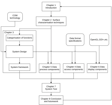
35]. There are 8 chapters in total. Figure 1.1 illustrates the relationships and the
connection between them:
Chapter 1 introduces the background and states the deficiencies of current software
systems for surface characterisation in respect to reusability, extensibility, maintainability
and customisation. The aims, objectives and approach of the research are put forward.
Chapter 2 provides a literature review and introduces common surface characterisation
22
Chapter 3 focuses on the design of flexible system architecture. Firstly, component based
development is discussed, which includes the framework of component based
architecture, current technologies for CBA and its advantages. Then, the flexible surface
characterisation system architecture is designed based on the categorisation of system
functions. Finally, the development models are discussed and applied to the development
of the system framework and functional components.
.
Chapter 1 Introduction
Chapter 2 Surface characterisation techniques
Categorisation of functions COM
technology
System Design
System framework Chapter 4 Data
access components Chapter 5 Data
process components
Chapter 6 Data display components Data format
specifications OpenGL,GDI+,etc.
Chapter 7 System Test
[image:24.612.107.487.223.579.2]Chapter 8 Conclusion and futurework Chapter 3
Figure 1.1: Thesis structure diagram.
Chapter 4 describes the design and development of data access components. This chapter
starts with the introduction of conventional surface file formats. Then, the internal surface
data structure is designed and the interface of data access components is defined.
Moreover, the SDF file component is selected as an example to demonstrate the
23
Chapter 5 presents the design and development of data process components. As the data
process components are more complex than the other two types of functional components,
the categorisation of them is discussed first. Then, the interface of each type of data
process components is defined respectively. Similarly, a case study concerning the
geometrical analysis component is finally given.
Chapter 6 elaborates the design and development of data display components. This
chapter starts with the introduction of computer graphics. Then, the interface of data
display components is defined. Finally, the implementation of 3D display component
using OpenGL technology is presented.
Chapter 7 deals with the system test and evaluation which is carried out by various test
cases and comparison with other systems.
Chapter 8 concludes the outcomes and contributions, and suggests possibilities for future
24
Chapter 2
Surface Characterisation Techniques
2.1
Introduction
Surface metrology, which is the measurement of the deviations of a workpiece surface
from its intended shape, is one of the fastest-growing areas of engineering and quality
management [36]. Surface texture is an important factor in determining how a real object
will interact with its environment, and it has been accepted as being significant in many
fields. What happens during the interaction between two surfaces can affect the
functionality and life span of a product, understanding the role of surface features in the
function of a component is vital for creating and producing effective product designs and
manufacturing protocols.
Using the fingernail and the eye was the original way to measure and assess the quality of
surfaces. However, this is subjective and arbitrary in the sense that evaluation of the
results is mostly determined by the tester. Surface features are usually too small to be
assessed effectively by such a ―touch and sight‖ [7]. The demand for effective methods to
extract these surface features has stimulated engineers to explore new characterisation
methods. Nowadays, surface characterisation techniques have made considerable
progress. Many mathematical algorithms have been adopted to extract the significant
surface topographical features, and these features can be represented and quantified by a
set of characterisation parameters, which are calculated after sequential data processing.
A series of GPS standards have also been released to the guarantee commonality of the
characterisation process. This chapter gives a literature review of such existing surface
characterisation and evaluation techniques.
2.2
Surface Verification Operator
It is well known that every workpiece is anticipated to satisfy all the criteria implied by
its design, and that is the natural purpose of manufacturing. Normally, a workpiece is
formed by different geometrical features and described by the inscription of sizes and
angles in its nominal form. There are many geometrical features available for the
designer to define the workpiece, these are described by various mathematical parameters
25
workpiece is to check whether the tolerances and specifications defined by designer are
met. Intuitively, a surface is a set of infinite points that separate a workpiece from its
surrounding. On a real workpiece only a limited number of points can be used
metrologically. Currently, the skin mode, which is a geometrical model of the physical
interface between a workpiece and its environment, is widely used for the verification
and evaluation of a workpiece [2].
The skin mode presents a description for geometrical product specification and
verification with its associated details and on this basis―every workpiece can be
geometrically defined and considered by applying manipulations of the workpiece
geometry. This determination is based on mathematical rules and definitions. This
therefore means that according to this determination every workpiece can be designed
and on the other hand according to the design it can be measured efficiently. The skin
model defines non-ideal features by consideration of ideal features at the workpiece
surface. A real feature is a non-ideal feature the shape which depends on the production
process and its conditions whereas ideal features exist only in theory [37].
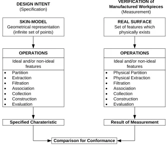
DESIGN INTENT (Specification) VERIFICATION of Manufactured Workpieces (Measurement) SKIN-MODEL Geometrical representation (infinite set of points)
REAL SURFACE
Set of features which physically exists
OPERATIONS
Ideal and/or non-ideal features
Partition
Extraction
Filtration
Association
Collection
Construction
Evaluation
Specified Charateristic Result of Measurement
Comparison for Conformance
OPERATIONS
Ideal and/or non-ideal features
Physical Partition
Physical Extraction
Filtration
Association
Collection
Construction
[image:27.612.137.472.401.692.2] Evaluation
26
Figure 2.1 shows the parallel procedures between ―Design Intent‖ and the ―Verification
of Manufactured Workpieces‖ so that they comply with the design intent [38]. The
Skin-Model is based on some general and basic definitions and using tools, which are named
―Operations‖ that can be compared with mathematical operations using arithmetic
techniques. The operations which are applied within the skin model are [39]:
1) Partition; used to identify bounded features.
2) Extraction; used to identify a finite number of points from a feature, with specific
rules.
3) Filtration; used to distinguish between roughness, waviness, structure, form, etc.
4) Association; used to fit ideal feature(s) to non-ideal feature(s) according to
specific rules, which are called criteria.
5) Collection; used to identify and consider some features together, which together
play a functional role.
6) Construction; used to build ideal feature(s) from other feature(s) whilst respecting
defined constraints.
7) Evaluation; used to identify either the value of a characteristic or its nominal
value and its limit(s). The evaluation is always used after the feature operation(s)
defining one specification or one verification.
In the Skin Model, no ordering of operations is implied in the above list. Various
verification operators can be found by these feature operations applied with different
orders, which are usually determined by the effects of each operation and the actual
requirements. Although there are no perfect verification operators that can be used for all
real workpieces or products, most of them may be verified by using the common operator
consisting of all operations listed in the skin model.
The Skin Model can also be extended and applied for surface characterisation and
evaluation in theory. When verifying a surface, several data processing steps are required
to extract significant surface features. Thus, the whole procedure is considered to be
analogous to a verification operator, while each data processing step is one operation. Not
27
of them are not necessary. For example, the operation ―partition‖ is not suitable for
surface data as the measured surface itself is a bounded feature of a workpiece. In the
field of surface metrology, to achieve a reasonable and logical evaluation, some
additional operations are used to extract specific features of surfaces. Regardless of
whether operations used for surface characterisation are defined in skin model or not,
these operations comprise a concrete surface verification operator. With different
operations or same operations but in different orders, various operators can be formed to
satisfy a variety of surface characterisation requirements.
Theoretically, any surface evaluation results should be acquired from a completed
verification operator and it will be meaningless to compare the evaluation results without
considering which verification operator is used. Whereas, during the procedure of surface
characterisation verification operators are often less emphasised and sometimes neglected.
Instead, the techniques used in each data processing step, namely operations, are
well-developed and widely used for various kinds of surfaces. To enable traceability and
comparability of evaluation results, it is necessary to keep records of all operations
adopted in order to realise the repeatable characterisation of any surfaces. Surface
verification operators can be used to precisely save and express those operations applied
during the surface characterisation process. Therefore, appropriate verification operators
for the realisation of surface characterisation should be encouraged and promoted widely.
At present, although no operators have been defined in ISO standards explicitly, one
operation chain has already been implied in ISO 25178 and it is widely accepted and used
for real surface evaluation. This operation chain can be thought as a standard operator for
general surface characterisation. Each operation involved in this operator has already
been separately defined in relevant GPS standards [11, 12, 40-46]. Generally, there are
four significant kinds of operations in one surface verification operator, and they
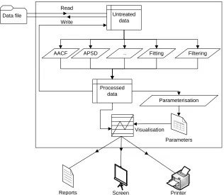
comprise measurement, fitting, filtering and parameterisation. Figure 2.2 shows the
flowchart of the evaluation of a surface with the standard verification operator. In
addition, metrologists can also generate their own verification operators for different
kinds of characterisation cases. Therefore, surface verification operators should be
supported in the characterisation system. Unfortunately, they are neglected in present
28
Surface measurement instruments
Results of evaluation Measurement data Primary surface S-F surface S-L surface Parameters S u rf a c e v e ri fi c a ti o n o p e ra to
rs Data access
[image:30.612.129.483.66.438.2]F-operator L-filter Parameters Calculation ISO5436-2 ISO25178-7 ISO3274 ISO25178-2 ISO13565 ISO16610 series ISO4287 G P S S ta n d a rd s
Figure 2.2: Standard surface verification operator [2].
Surface analysis and characterisation usually starts from the measurement data which is
considered to be the digital representation of the original ―real‖ surface. The
measurement data is acquired from metrology instruments and usually consists of a set of
discrete height information defined over the measurement plane. As various measurement
techniques and measurement environments may lead to different measurement data and
the accuracy and precision of the measurement instruments used have a significant
influence on the final evaluation result, it is necessary to measure a surface with an
appropriate instrument. In the past, a judgement was of the measurement technique
appropriateness from visual inspection of the magnified representation of the surface
which is reconstructed from measurement data. Nevertheless, it might be too simplistic to
29
height data, a set of sequential operations are required to extract salient features from the
measurement data.
The standard surface verification operator mainly focuses on extracting surface roughness
and waviness, and quantifying them for quality assessment. For a surface characterisation
system, the initial step is to import the measured data which is stored in a digital file with
a specific file format. Although profile and areal data formats have already been defined
in ISO 5436-2 and ISO 25178-71 respectively, there are still a number of file formats
widely used, in practice which are usually specified by instrument companies. For
example, SUR is a surface format used by Mountains map and Talymap, while OPD is a
Wyko specified format. It is necessary to have knowledge of the file format specification
in order to access relevant measurement data files. However the fact is that these file
formats can only be accessed by their conterpart surface characterisation systems. This is
mainly caused by two reasons: the file format is not open because of the confidentiality
of business; and it is impossible to include all these file formats in a given
characterisation system. Hence, a standard file format is greatly encouraged for reasons
of the compatibility and interchangeability of surface data files.
5.98m m
5.98m m
687.04um
0.00
257.02um
0.00
F-operator 5.98m
m
5.98m m
Primary Surface S-F Surface
Figure 2.3: F-operator—first order polynomial fitting.
After importing the measurement data to a characterisation system, the reconstructed
surface without any processing is defined as the primary surface. When measuring a
surface, even after careful alignment with the measurement instrument, there is still some
residual slope and slight curvature. So fitting is considered to be the first step of the
30
the F-operator and it removes the form component from the primary surface [12]. Figure
2.3 shows an example of using the first order polynomial fitting to remove the tilt form.
The S-F surface is derived from the primary surface by the fitting operation, and the
subsequent operation is filtering. Filtering is very important in surface analysis, and it is
mostly used as the L-filter defined in ISO 25178-2. The action of filtering is to extract the
significant information from the measurement data for further analysis. The S-F surface
topography can be divided into two parts by filtering, and usually the more significant
part is the high-frequency band which is termed the S-L surface (as shown in Figure 2.4).
As the surface feature of interest may be varying and the requirements of the extraction
can also be diverse, taking advantage of the suitable filter with the right parameters can
contribute to an effective extraction.
L-filter
5.98m
m 5.98mm
5.98m m
5.98m m
0.00 0.00
257.02um
154.53um
S-F Surface S-L Surface
Figure 2.4: L-filter—Gaussian regression filtering.
In the last decade, significant advances have been achieved in filtering techniques.
Although the Gaussian filter is widely used today and is referred to as the standard filter,
it suffers from several shortcomings. The profile has distortion near the edges, and it does
not follow the texture in the presence of large form deviation and is not robust against
outliers. The Spline and Gaussian regression filters overcome the problem of edge
distortion and poor performance in the presence of large form, while the robust Spline
and robust Gaussian regression filters overcome all three problems[47, 48].
Wavelet-based filters provide an efficient way to partition a profile into multiple narrow
wavelength bands. Morphological filters provide an entirely different perspective to
filtering. They are curvature dependent instead of wavelength dependent. Features with
31
with larger curvatures are touched [48, 49]. Therefore, the selection of filter type is
critical when acquiring elements of the surface texture such as waviness and roughness.
Once the S-L surface is obtained, it is then more useful to calculate surface topography
parameters. Parameter calculation is mostly but not always based on the S-L surface
which is normally regarded as the ―expected‖ surface. Most of the profile parameters are
defined in ISO 4287 [11], while the areal parameters are defined in ISO 25178-2 [50].
Different parameters reflect the surface texture from different perspectives. There is no
universal parameter that represents the surface texture well for all cases, but there are
numerous parameters that successfully characterise the surface for special applications.
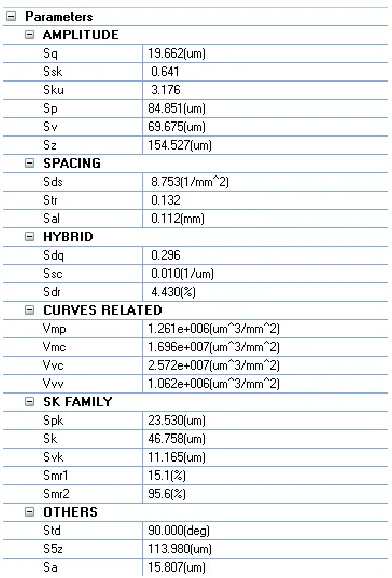
Figure 2.5 shows the result of a typical parameter calculation for the previous S-L surface
[image:33.612.209.405.308.597.2]presented in Figure 2.4.
Figure 2.5: Calculation results of standard surface areal parameters.
These parameters are calculated according to their definitions in ISO 25178-2. For
example, the Sa value, which is the most commonly used parameter in areal surface
texture, is the arithmetic mean of the magnitude of the deviation of the surface from the
32
1 2 1 2
1 0 0
,
L L
a L L
S
f x y f dxdy (2.1)Where f is the height of the mean plane and L1 and L2 are the extent of the sample. F (x,
y) is the surface height at (x, y). takes the absolute value.
This standard verification operator provides a vital and effective method of quantifying
surface topography. Many practical verification operators can be derived from the
standard operator by applying different kinds of implementation technique or changing
the parameters of certain mathematical operations. Moreover, not all surfaces are suitable
to be evaluated by this standard verification operator and its derived operators. In these
cases it may be more logical to create some special verification operators for a specific
case of surface characterisation and evaluation, depending on the functions of the
surfaces to be analysed.
2.3
Surface Measurement
The earliest methods of measuring surfaces were using the thumb nail and the eye.
Although both methods were effective, they were completely subjective, did not provide
quantitative results and required high skill levels. Surfaces are increasingly produced by a
large variety of manufacturing processes, where each process leaves its own fingerprint
on surface of workpieces, it is impossible to utilise subjective methods to assess these
―fingerprints‖ by using such crude techniques. Demands for reliable evaluation results led
to two parallel branches of instrumentation: one following the tactile example of the nail,
the other imitating the eye, namely, the stylus methods and the optical methods. Currently,
these are the two broad solutions for surface measurement, and they evolve to measure
different types of surfaces [6]. There are other methods developed for surface
measurement including capacitance techniques pneumatic methods but these are now
rarely used.
2.3.1 Stylus Methods
Stylus methods were the first techniques developed for surface measurement. In the
second half of the 1930s, a number of companies began to develop instruments to
generate the objective information from the original surface. In 1941 for example, the
33
guises was the first one to introduce a graphical chart representing the roughness profile
[6]. However, the Brush development company in the USA was the first to coin the term
profilometer [4]. From that time, the measurement of surface texture was largely based
on profile profilometr. The surface profilometers instruments did not appear until the
beginning of the 1980s and they were largely based on adaptations of existing
profilometers using extra translation stages and independent references.
α Referenc
e Surface
Measured Surface
Calliper
(a) (b)
α
Measured Surface
Calliper
Figure 2.6: The stylus principle.
The stylus method essentially uses a form of calliper, where one arm makes contact with
the surface to be measured while the other arm contacts a reference surface [52]. The arm
contacting the measured surface ends with a diamond stylus whose tip dimension can
penetrate the detailed geometry of the measured surface. The other arm contacts the
reference surface. Figure 2.6(a) shows the basic configuration. A more common
methodology is to use the measured surface as a reference by using a much blunter stylus
and referencing the measurements to the blunter stylus (the skid) path as shown in Figure
2.6(b). Here the ‗skid‘ technique provides an ‗intrinsic‘ reference. What needs to be
measured is the deviation from the intended surface shape rather than the position or
dimension, so the actual position of the reference relative to the measured surface is not
important [7].
The most important factor of a stylus measurement system is the stylus as the name
implies and it was Schmaltz pushed the idea forward the development of the mechanical
probe [53]. As the tips contact the sample surface, it is necessary to choose hard materials
34
shows two different stylus types. The conical form is the most common stylus type by
now [51].
Cone Pyramid
Figure 2.7: Two types of stylus―Cone and Pyramid [51].
During the measurement, stylus geometry and tip radius needs to be considered as shown
in Figure 2.8. The tip can be infinitely sharp but still not penetrate completely into a
surface groove or valley, in other words, the dimension of the features that can be
measured is determined by the stylus radius. Moreover, if the tip is too sharp, it is much
easier to scratch/damage the measured surface and wear the tip. The selection of a stylus
mainly depends on the degree of spatial resolution desired. For a rough surface whose
roughness is of the order of microns, there is no need to use a very small stylus. In fact, a
stylus with a 10 micron tip radius would ensure reliable measurements and longer tip life.
Stylus
Figure 2.8: Stylus slope effect.
In addition, the process of stylus measurement can be considered as a form of mechanical
filtering. Spatial features smaller than tip radius cannot be measured and consequently
this means that the user will not gain any information that is below the spatial resolution
of the stylus.
In practice for areal measurements, a scanning routine which specifies scanning
parameters such as length, speed and sampling rate needs to be applied to achieve <
![Figure 2.2: Standard surface verification operator [2].](https://thumb-us.123doks.com/thumbv2/123dok_us/325743.1033648/30.612.129.483.66.438/figure-standard-surface-verification-operator.webp)
![Figure 2.9: Path of light in Michelson interferometer [56].](https://thumb-us.123doks.com/thumbv2/123dok_us/325743.1033648/38.612.200.407.147.361/figure-path-light-michelson-interferometer.webp)
![Figure 2.10: Amplitude-wavelength plot of different instruments for surface measurements [61]](https://thumb-us.123doks.com/thumbv2/123dok_us/325743.1033648/40.612.145.469.131.394/figure-amplitude-wavelength-plot-different-instruments-surface-measurements.webp)