HOMEOSTATIC-INSPIRED CONTROLLER ALGORITHM
FOR A HYBRID-DRIVEN AUTONOMOUS UNDERWATER
GLIDER
By
KHALID BIN ISA
Thesis submitted in fulfillment of the requirements
for the degree of
Doctor of Philosophy
iii
TABLE OF CONTENTS
Acknowledgements ii
Table of Contents iii
List of Tables x
List of Figures xii
List of Abbreviatons xix
List of Symbols xxii
Abstrak xxvi
Abstract xxviii
CHAPTER 1 - INTRODUCTION
1.1 Background 1
1.2 Problem Statements 4
1.3 Research Objectives 6
1.4 Research Scopes 6
iv CHAPTER 2 - LITERATURE REVIEW
2.1 Introduction 12
2.2 Historical Overview of AUV and AUG 12
2.2.1 Autonomous Underwater Vehicle (AUV) 14
2.2.2 Autonomous Underwater Glider (AUG) 18
2.3 Autonomous Underwater Glider Designs and Characteristics 21
2.3.1 Mechanical Designs and Characteristics 24
2.3.2 Electronic Designs and Characteristics 26
2.3.3 Control Mechanisms 28
2.3.4 Performance Characteristics 30
2.4 Modelling of AUVs and AUGs 32
2.5 Control Methods of the AUVs and AUGs 34
2.5.1 Proportional-Integral-Derivative (PID) 34
2.5.2 Linear Quadratic Regulator (LQR) 36
2.5.3 Sliding Mode Control (SMC) 37
2.5.4 Adaptive Control 38
2.5.5 Neural Networks Control 39
2.5.6 Fuzzy Logic Control (FLC) 41
2.6 Homeostasis and the Homeostatic Control System 43
2.6.1 Overview of Homeostasis 43
v
2.6.3 The Nervous System 48
2.6.4 The Endocrine System 49
2.6.5 The Immune System 50
2.7 Summary 53
CHAPTER 3 - METHODOLOGY
3.1 Introduction 55
3.2 Research Design 55
3.3 System Design 61
3.3.1 Buoyancy-Driven Mode System 64
3.3.2 Propeller-Driven Mode System 67
3.3.3 Hybrid-Driven Mode System 69
3.4 Summary 69
CHAPTER 4 - MODELLING OF THE HYBRID-DRIVEN UNDERWATER GLIDER
4.1 Introduction 71
4.2 Kinematics Model 71
4.2.1 Reference Frames 72
4.2.2 Kinematics 73
vi
4.2.4 Current Frame 76
4.3 Dynamics Model 78
4.3.1 Glider Configuration and Characteristics 78
4.3.2 Glider Masses Configuration 80
4.3.3 Wing and Rudder Configuration 82
4.3.4 System Inertia Matrix 83
4.3.5 Coriolis and Centripetal Forces and Moments 86
4.3.6 Damping Forces and Moments 88
4.3.7 Restoring Forces and Moments 91
4.4 Hydrodynamics Estimation 92
4.4.1 Glider Geometrical Definitions and Hydrodynamic Components 92 4.4.2 The Lift and Drag Coefficients of the Wing-Body Area from
the Slender-body Theory 94
4.4.3 The Lift and Drag Coefficients of the Tail Area from the
Slender-body Theory 96
4.4.4 The Lift and Drag Coefficients from CFD 97
4.5 Nonlinear Equations of Motion 97
vii
CHAPTER 5 - THE HOMEOSTATIC CONTROLLER DESIGN AND ALGORITHM
5.1 Introduction 101
5.2 Artificial Homeostatic Controller Design 101
5.3 Artificial Neural Network (ANN) 107
5.4 Artificial Endocrine System (AES) 111
5.5 Artificial Immune System (AIS) 114
5.6 Homeostatic Controller Algorithm 119
5.7 Summary 122
CHAPTER 6 - PROTOTYPE DEVELOPMENT AND SYSTEM INTEGRATION
6.1 Introduction 123
6.2 3D Model of The Hybrid-Driven AUG 123
6.3 Mechanical Design and Fabrication 126
6.3.1 Nose, Hull and Tail 128
6.3.2 Wings and Rudder 131
6.3.3 Internal Frame 132
6.3.4 Ballast Pump 133
6.3.5 Internal Sliding Mass 134
viii
6.4.1 Controller Module 136
6.4.2 Sensor Module 138
6.4.3 Internal Actuator Module 140
6.4.4 External Actuator Module 142
6.4.5 Communication Module 143
6.4.6 Data Logger Module 144
6.5 Summary 145
CHAPTER 7 - RESULTS AND DISCUSSION
7.1 Introduction 146
7.2 Hydrodynamics Estimation Simulation 146
7.2.1 Hydrodynamics Analyses Based on Slender-body theory 146
7.2.2 Hydrodynamics Analyses Based on CFD 155
7.2.3 Comparison of Hydrodynamics Coefficients between
Slender-body Theory and CFD 161
7.3 Homeostatic Control System Simulation 165
7.3.1 Open-loop System of the Nonlinear Model 166 7.3.2 Controllability, Observability and Stability Analysis of the
Open-Loop System 168
ix
7.3.4 Analysis and Comparison of Homeostatic Controller
Performance among Different Glider Models 187 7.4 Benchmarking of Homeostatic Controller Performance 196
7.5 Prototype Testing and Experimentation 204
7.5.1 Waterproof and Buoyancy Test 204
7.5.2 Functionality and Reliability Test 206
7.5.3 Operational and Sea Trial Test 214
7.5.4 Real-Time Open-Loop System Test 216
7.5.5 Real-Time Closed-Loop System Test and Validation 222
7.6 Summary 227
CHAPTER 8 - CONCLUSION AND FUTURE WORK
8.1 Conclusion 229
8.2 Future Work 231
REFERENCES 234
x
LIST OF TABLES
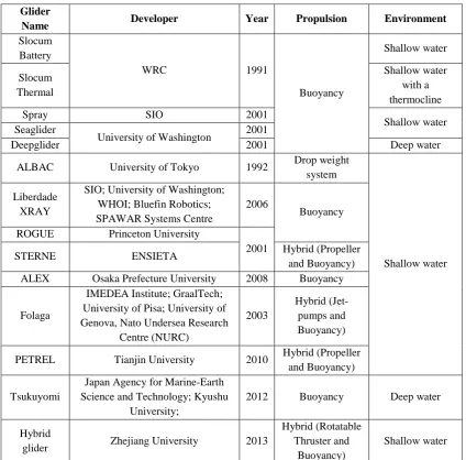
Table 2.1 General descriptions of the AUGs 23
Table 2.2 Mechanical designs and characteristics of the AUGs 25 Table 2.3 Electronic designs and characteristics of the AUGs 27
Table 2.4 Control mechanisms of the AUGs 29
Table 2.5 Performance characteristics of the AUGs 31 Table 2.6 The artificial homeostasis components by Neal and Timmis
(2003) 45
Table 2.7 AUG designs and control methods 54
Table 4.1 Glider characteristics 79
Table 7.1 Drag force coefficient for four velocities of each area 148 Table 7.2 Drag force coefficient for four angles of attack of each area 149 Table 7.3 Lift force coefficient for four velocities of each area 150 Table 7.4 Lift force coefficient for four angles of attack of each area 151
Table 7.5 Linearisation operating point 168
Table 7.6 Controllability and observability over the system order 169 Table 7.7 Desired Euler angles for the simulation 172 Table 7.8 Translation and angular velocities for the straight gliding
motion 177
Table 7.9 Predicted control inputs 180
Table 7.10 Difference percentage of gland stimulation rate between the systems with disturbance and without disturbance 182 Table 7.11 Difference percentage of hormone concentration between the
xi
Table 7.12 Comparison of the weights 187
Table 7.13 Desired Euler angles for the comparison 188
Table 7.14 Desired outputs for the comparison 196
Table 7.15 Actual pitch angle achieved by the controller 198
Table 7.16 Settling time for pitch angle 198
Table 7.17 Comparison of the translation and angular velocities 201 Table 7.18 Comparison of the position of the sliding mass in the
𝑥-direction 203
Table 7.19 Comparison of the ballast masses 203
Table 7.20 Weight distribution 206
xii
LIST OF FIGURES
Figure 1.1 Gliding motion of autonomous underwater glider (AUG) 2 Figure 2.1 The overview of the literature review 13 Figure 2.2 The basic behavioural architecture of the adaptive artificial
neural-endocrine by Timmis et al. (2009) 47 Figure 2.3 Binding of hormones by Castro and Timmis (2002) 50 Figure 2.4 The adaptive immunity mechanism by Castro and Von
Zuben (1999) 52
Figure 3.1 The framework diagram of methodology 56
Figure 3.2 The drawing of AUG 57
Figure 3.3 The general system architecture of the hybrid-driven AUG 62 Figure 3.4 System flowchart of the buoyancy-driven mode 66 Figure 3.5 System flowchart of the propeller-driven mode 68 Figure 3.6 System flowchart of the hybrid-driven mode 70
Figure 4.1 The glider's reference frames 72
Figure 4.2 Glider configuration 78
Figure 4.3 Geometrical definitions of the glider 93 Figure 4.4 Hydrodynamics components of the glider 94 Figure 5.1 The negative feedback of body temperature control system 102 Figure 5.2 The positive feedback of childbirth control system 103 Figure 5.3 The negative feedback of the hybrid-driven AUG motion
control system 104
Figure 5.4 The artificial homeostatic control framework of the glider
xiii
Figure 5.5 The block diagram showing how to design the homeostatic
controller 106
Figure 5.6 The ANN forward model of the glider plant 108 Figure 5.7 The principle of clonal selection by De Castro and Von
Zuben (2000) 116
Figure 5.8 The homeostatic controller algorithm 121 Figure 6.1 The 3D model of the glider using SolidworksTM 124 Figure 6.2 The evaluation of glider mass properties 126 Figure 6.3 Final prototype of the hybrid-driven autonomous underwater
glider 127
Figure 6.4 Nose and echo sounder fabrication 128
Figure 6.5 The hull fabrication 129
Figure 6.6 The tail fabrication 130
Figure 6.7 The configuration of (a) wings, and (b) rudder 131 Figure 6.8 Internal frame of the hybrid-driven AUG 133 Figure 6.9 Ballast pump installation and configuration 134
Figure 6.10 Internal sliding mass installation 135
Figure 6.11 Bottom view of the internal sliding mass 135
Figure 6.12 Controller module 136
Figure 6.13 MATLABTM code to communicate with the Arduino via
serial communication 137
Figure 6.14 Arduino code to read data from MATLABTM 138
Figure 6.15 IMU and Compass 138
xiv
Figure 6.17 Ballast pump control circuit 141
Figure 6.18 Linear actuator control circuit 141
Figure 6.19 Phoenix Ice2 HV40 ESC 142
Figure 6.20 The SC08A servo controller 143
Figure 6.21 The DS-XTend RF module 144
Figure 6.22 SD card data logger 145
xv
Figure 7.19 Drag force coefficient over the velocity of the glider 159 Figure 7.20 Moment coefficient over the angle of attack of the glider 160 Figure 7.21 Moment coefficient over the velocity of the glider 160 Figure 7.22 Lift coefficient comparison between CFD and Slender-body
theory for velocity of 0.5 m/s 161
Figure 7.23 Drag coefficient comparison between CFD and Slender-body
theory for velocity of 0.5 m/s 162
Figure 7.24 Lift coefficient comparison between CFD and Slender-body
theory for AoA of 2o 163
Figure 7.25 Drag coefficient comparison between CFD and Slender-body
theory for AoA of 2o 163
Figure 7.26 Moment coefficient comparison between CFD and Slender-body
theory for AoA of 2o 164
Figure 7.27 Moment coefficient comparison between CFD and Slender-body
theory for velocity of 0.5 m/s 165
Figure 7.28 The open-loop control system of the hybrid-driven AUG 166 Figure 7.29 Simulink model for the linear model extraction 167 Figure 7.30 System poles and zeros of the hybrid-driven mode 170 Figure 7.31 System poles and zeros of the buoyancy-driven mode 171 Figure 7.32 System poles and zeros of the propeller-driven mode 171 Figure 7.33 Training performance of the neural network (NN) 173 Figure 7.34 Training regression of the neural network (NN) 173 Figure 7.35 System poles and zeros of the NN glider model for
hybrid-driven mode 174
xvi
Figure 7.37 The translational velocities for the straight gliding motion 176 Figure 7.38 The angular velocities for the straight gliding motion 176 Figure 7.39 Position and forces of the sliding mass, and mass of the
ballast pump for the straight gliding motion 178 Figure 7.40 Predicted control input for wings and rudder for the straight
gliding motion 179
Figure 7.41 Predicted control input for sliding mass and ballast pump for
the straight gliding motion 179
Figure 7.42 Gland stimulation rate and concentration of the AES 181
Figure 7.43 Initial antibody population 184
Figure 7.44 The best antibody 185
Figure 7.45 Cloned and matured antibody 186
Figure 7.46 Optimised antibody 186
Figure 7.47 Comparison of the pitch angle, surge and heave velocity, and pitch rate between the buoyancy-driven and hybrid-driven
models 189
Figure 7.48 Comparison of the sliding mass and ballast pump outputs
between the buoyancy-driven and hybrid-driven models 190 Figure 7.49 Comparison of the sliding mass and ballast control inputs
between the buoyancy-driven and hybrid-driven models 192 Figure 7.50 Comparison of roll and yaw angles between the propeller-driven
and hybrid-driven models 193
Figure 7.51 Comparison of the surge and sway velocities between the
xvii
Figure 7.52 Comparison of roll and yaw rates between the propeller-driven
and hybrid-driven models 194
Figure 7.53 Comparison of the wings and rudder control inputs between the propeller-driven and hybrid-driven models 195 Figure 7.54 Comparison of the controllers performance on Euler angles 197 Figure 7.55 Comparison of the controllers performance on translational
velocities 200
Figure 7.56 Comparison of the controllers performance on angular
velocities 200
Figure 7.57 Comparison of the controllers' performance on the sliding
mass positions and forces, and the ballast mass 202
Figure 7.58 Waterproof and buoyancy test 205
Figure 7.59 Compass module reliability test 207
Figure 7.60 IMU reliability test of the roll angle 209 Figure 7.61 IMU reliability test of the pitch angle 209
Figure 7.62 Echo sounder reliability test 211
Figure 7.63 Transmitted GPS data 212
Figure 7.64 Threaded rod of the ballast pump 213
Figure 7.65 The motion of the internal sliding mass 213 Figure 7.66 Buoyancy and propeller-driven test at the Penarik Beach 215 Figure 7.67 Propeller-driven test at the sea of Bidong Island 216 Figure 7.68 Buoyancy-driven test at the sea of Bidong Island 216 Figure 7.69 Real-time open-loop system test of the hybrid-driven mode 217 Figure 7.70 Real-time open-loop system data log of the hybrid-driven
xviii
Figure 7.71 Real-time Euler angles from the open-loop system of the
hybrid-driven mode 219
Figure 7.72 Real-time angular velocities from the open-loop system of the
hybrid-driven mode 219
Figure 7.73 Real-time temperature, depth, and front distance from the
open-loop system of the hybrid-driven mode 220 Figure 7.74 Real-time GPS data from the open-loop system of the
hybrid-driven mode 221
Figure 7.75 Real-time homeostatic control system test of the
hybrid-driven mode 223
Figure 7.76 Real-time homeostatic control system test data log of the
hybrid-driven mode 223
Figure 7.77 Real-time Euler angles from the homeostatic control system of
the hybrid-driven mode 224
Figure 7.78 Real-time angular velocities from the homeostatic control
system of the hybrid-driven mode 225
Figure 7.79 Real-time temperature, depth and front distance from the
homeostatic control system of the hybrid-driven mode 226 Figure 7.80 Real-time GPS data from the homeostatic control system of
xix
LIST OF ABBREVIATIONS
2D - Two-Dimensional
3D - Three-Dimensional
Ab - Antibody
ADCP - Acoustic Doppler Current Profiler AES - Artificial Endocrine System
Ag - Antigen
AHRS - Attitude and Heading Reference System AI - Artificial Intelligence
AIS - Artificial Immune System ANN - Artificial Neural Network AoA - Angle of attack
AOSN - Autonomous Oceanographic Sampling System AUG - Autonomous Underwater Glider
AUV - Autonomous Underwater Vehicle BEC - Battery Eliminator Circuit
BPAUV - Battlespace Preparation Autonomous Underwater Vehicle
CA - Centre of Mass
CAD - Computer-Aided Design
CB - Centre of Buoyancy
CFD - Computational Fluid Dynamics CG - Centre of Gravity
CSA - Clonal Selection Algorithm
xx
DC - Direct current
DOF - Degree-of-Freedom DVL - Doppler Velocity Logger ESC - Electronic Speed Control FLC - Fuzzy Logic Control
GA - Genetic Algorithm
GPS - Global Positioning System HDPE - High Density Polyethylene
HF - High Frequency
IDE - Integrated Development Environment IMU - Inertial Measurement Unit
Li-Po - Lithium polymer
LQG - Linear-Quadratic-Gaussian LQR - Linear-Quadratic Regulator MIMO - Multiple-Input-Multiple-Output MLP - Multilayer Perceptron
MMS - Marine Systems Simulator MPC - Model Predictive Control
NACA - National Advisory Committee for Aeronautics NMEA - National Marine Electronics Association OMLPNN - Online Multilayer Perceptron Neural Network
PC - Personal Computer
PD - Proportional-Derivative
PID - Proportional-Integral-Derivative
xxi PWM - Pulse Width Modulation
RC - Radio Control
REMUS - Remote Environmental Monitoring Units
RF - Radio Frequency
ROV - Remotely Operated Vehicle
SCL - Serial clock
SD - Secure Digital
SDA - Serial data signal
SIFLC - Single Input Fuzzy Logic Control SIO - Scripps Institution of Oceanography SISO - Single-Input-Single-Output
SMC - Sliding Mode Control
SODMN - Self-Organization Direction Mapping Network SONCS - Self-Organizing Neural-net Control System SPAWAR - Space and Naval Warfare
SPI - Serial Peripheral Interface
SPURV - Self-Propelled Underwater Research Vehicle UARS - Unmanned Arctic Research Submersible UART - Universal asynchronous receiver/transmitter USBL - Ultra-short Baseline
UUV - Unmanned Underwater Vehicle VHF - Very High Frequency
xxii
LIST OF SYMBOLS
𝐶𝐴(𝑉) - Added Coriolis-centripetal matrix
𝜏𝐴 - Added mass forces and moments
𝑀𝐴 - Added mass inertia matrix
𝐴𝐶𝑡 - Aerodynamic/hydrodynamic centre of tail area
𝐴𝐶𝑤𝑏 - Aerodynamic/hydrodynamic centre of wing-body area
𝛼 - Angle of attack
𝜔2 - Angular velocities
𝐴ℎ𝑡 - Axial force of tail area
𝐴𝑤𝑏 - Axial force of wing-body area
𝑚𝑏 - Ballast point mass
𝑥𝑏𝑦𝑏𝑧𝑏 - Body reference frame axes
𝐵 - Buoyancy
𝐶(𝑉) - Coriolis-centripetal forces and moments
𝐷(𝑉) - Damping forces and moments
𝜏𝐷𝑏 - Damping forces on glider body
𝜏𝐷𝑙𝑤 - Damping forces on left wing
𝜏𝐷𝑟𝑤 - Damping forces on right wing
𝜏𝐷𝑟 - Damping forces on rudder
𝛿𝑙𝑤 - Deflection angle of left wing
𝛿𝑟𝑤 - Deflection angle of right wing
𝛿𝑟 - Deflection angle of rudder
xxiii
𝐶𝐷 - Drag coefficient
𝑚𝑤 - Fixed point mass
𝜏 - Forces and moments vector action on glider body
𝜏𝐹𝐾 - Froude-Kriloff forces
𝑈 - Glider speed
𝑚𝑟𝑏 - Glider total mass
𝑉 - Glider velocity
𝑔 - Gravitational acceleration
𝑤 - Heave
𝑚ℎ - Hull mass
𝑥ℎ𝑐 - Hydrodynamic centre
𝐼𝑐 - Inertia matrix about the centre of gravity
𝐼𝑜 - Inertia matrix about the origin
𝑥𝑖𝑦𝑖𝑧𝑖 - Inertial frame axes
𝑚𝑝 - Internal moving mass
𝑇 - Kinetic enegry
𝐿 - Length of glider body
𝐶𝐿 - Lift coefficient
𝐷 - Linear damping
𝑚 - Mass of fluid displaced
𝑃𝑚 - Middle point position
𝐶𝑀 - Moment coefficient
𝑥𝑚 - Moment reference location
xxiv
𝐷𝑛(𝑉) - Nonlinear damping matrix
𝑁ℎ𝑡 - Normal force of tail area
𝑁𝑤𝑏 - Normal force of wing-body area
𝜃 - Pitch angle
𝑞 - Pitch rate
𝐴𝑝 - Planform area
𝜏𝑃 - Propeller forces
𝑟 - Radius
𝐴𝑟 - Reference area
𝑉𝑟 - Relative velocities and accelerations to water currents
𝑔(𝑛) - Restoring forces and moments
𝐶𝑅𝐵(𝑉) - Rigid-body Coriolis-centripetal matrix
𝑀𝑅𝐵 - Rigid-body inertia matrix
∅ - Roll angle
𝑝 - Roll rate
𝑚𝑝𝑦 - Rotating moving mass
𝐽(𝜂) - Rotation and transformation matrix of Euler angles
𝛿 - Rotation angle of the wings and rudder
𝑅 - Rotation matrix
𝑅𝑙𝑤 - Rotation matrix of left wing
𝑅𝑟𝑤 - Rotation matrix of right wing
𝑅𝑟 - Rotation matrix of rudder
𝜔�2 - Skew-symmetric matrix of angular velocities
xxv
𝑃𝑝 - Sliding mass net forces
𝑚𝑝𝑥 - Sliding moving mass
𝑆𝑏 - Surface of glider body
𝑆𝑟 - Surface of rudder
𝑆𝑤 - Surface of wings
𝑢 - Surge
𝑣 - Sway
𝑀 - System inertia matrix
𝜔1 - Translational velocities
𝑟𝑏 - Vector of ballast mass position
𝑟𝑐𝑏 - Vector of centre of buoyancy position
𝑟𝑐𝑔 - Vector of centre of gravity position
𝛩 - Vector of Euler angles
𝑏 - Vector of glider position
𝑟𝑝 - Vector of internal moving mass
𝑉𝑐 - Velocities and accelerations of water currents
𝑉𝑐ℎ - Volume of cylindrical hull
𝑉𝑒ℎ - Volume of ellipsoidal hull
∇ - Volume of glider body
𝜌 - Water density
𝑊 - Weight
𝑠 - Wing half-span
𝜓 - Yaw angle
xxvi
ALGORITMA PENGAWAL BERINSPIRASIKAN HOMEOSTATIK UNTUK PELUNCUR BAWAH AIR BERAUTONOMI YANG DIPACU SECARA
HIBRID
ABSTRAK
xxvii
xxviii
HOMEOSTATIC-INSPIRED CONTROLLER ALGORITHM FOR A HYBRID-DRIVEN AUTONOMOUS UNDERWATER GLIDER
ABSTRACT
xxix
model predictive control (MPC); 9 seconds faster than the linear-quadratic regulator (LQR); 6.5 seconds faster than the neural network (NN) controller; and 3.75 seconds faster than the neuroendocrine controller. In addition, the homeostatic controller was able to optimise the ballast mass and distance of the sliding mass in order to achieve the desired pitch angle by shortening the sliding mass distance up to 53.7% and reducing the ballast mass up to 17.7% when compared with the LQR and MPC. Overall, the homeostatic controller has achieved the best performance compared with the LQR, MPC, NN and neuroendocrine controllers. Furthermore, the validation analyses between the simulation and experimental results have shown that the homeostatic control system produces very satisfactory performance, with the homeostatic controller able to achieve the desired angle.
1 CHAPTER 1
INTRODUCTION
1.1 Background
The oceans play an essential role in the future existence of all human beings. The bountiful oceanic resources such as food, oil, and gas have inspired humans to explore the ocean and marine environment for the benefit of mankind. Although the animate and inanimate ocean's resources are critical to human life, the ocean can also threaten human life through natural phenomena such as tsunamis and underwater earthquakes. These effects have made many researchers take progressive action to explore the full depths of the ocean resources as well as to monitor ocean activities.
2
As a consequence, the interest in developing autonomous underwater gliders (AUGs) as a new breed of AUVs has experienced a substantial increase due to the high demand in long-term underwater exploration applications. Existing AUGs such as Slocum (Webb et al., 2001), Spray (Sherman et al., 2001), Seaglider (Eriksen et al., 2001), and Deepglider (Osse and Eriksen, 2007) were developed as tools for oceanographic applications. They were designed to meet the demand for underwater vehicles with low energy consumption that could be used for long-term deployment.
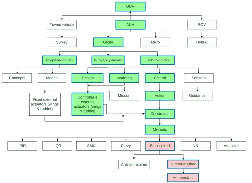
[image:30.595.118.520.424.587.2]The typical design of the AUG is buoyancy-driven, having fixed wings, internal masses, a ballast pump, and a rudder. Thus, the buoyancy-driven AUG moves vertically through the ocean water column by controlling their pitching angle and depth through the internal masses and ballast pump, respectively. Figure 1.1 shows the motion of a buoyancy-driven autonomous underwater glider.
Figure 1.1: Gliding motion of autonomous underwater glider (AUG)
3
have limited external moving surfaces; and have major constraints for manoeuvring and control.
In terms of controller methods, numerous classical and modern control systems have been used to control AUVs and AUGs. Simple proportional-integral-derivative (PID) controllers and linear-quadratic regulators (LQR) have been used to control most existing gliders attitude and motion (Bachmayer et al., 2003; Kan et al., 2008; Leonard and Graver, 2001; Mahmoudian and Woolsey, 2008; Seo et al., 2008; Wang et al., 2009). The nonlinear robust control method such as sliding mode control (SMC) has also been implemented to control underwater gliders (Jun et al., 2009; Yang and Ma, 2010). However, the main drawback in SMC is the chattering effect, which can degrade the performance of the system, and may even lead to instability. Although these controller methods have already demonstrated acceptable control performance, the underwater environment imposes several restrictions on the design of the glider and its controller. Due to the nonlinearity and complexity of the glider dynamics and underwater environment, the glider should be truly autonomous, which means that it will operate steadily and adapt to its environment. In order to have those abilities, biologically-inspired control systems should be explored.
4
homeostasis, which maintains a stable state in the face of massively changing conditions.
1.2 Problem Statements
The problem statements of this research work are divided into two aspects: the controller and the underwater glider platform. Thus, the problem statements of this research work are as follows:
1.2.1 The high nonlinearity of the glider dynamics and underwater disturbances limit the controller adaptability while maintaining the overall stability
Although researchers have previously proposed and implemented several controller methods to control AUVs and AUGs, they still face difficulties in tuning the controller gains to maintain overall stability and high quality response when the control performance degrades due to significant changes in the vehicle dynamics and its environment. The high nonlinearity and time-variance of underwater vehicle dynamics, and unpredictable underwater disturbances such as the fluctuating ocean currents are the main reasons that make it difficult to control underwater vehicles such as the underwater glider (Amin et al., 2010a; Budiyono, 2009; Yuh, 2000). Thus, it is highly desirable to design a controller that is self-tuning and has an adaptive ability to deal with these constraints.
5
and to adapt to the changing conditions. Several researchers have used neural networks to control AUVs (Ishii and Ura, 2000; Li and Lee, 2005; van de Ven et al., 2005; van de Ven et al., 2007). Although the neural network has the ability to overcome the constraints, it has a low convergence rate (Bao et al., 2011). In addition, none of the previous research works have implemented neural networks to control underwater gliders.
1.2.2 Under-actuated platform with limited external control surfaces reduces the
underwater glider efficiency in terms of speed and manoeuvrability
6 1.3 Research Objectives
The main objective of this research is to design a homeostatic controller algorithm for a hybrid-driven autonomous underwater glider. Thus, the sub-objectives are:
i. To develop a mathematical model of a hybrid-driven autonomous underwater glider.
ii. To design, develop and implement a homeostatic controller algorithm of the glider motion control system for the highly nonlinear ocean environment.
iii. To design and develop the hybrid-driven autonomous underwater glider platform for oceanographic sensing applications.
1.4 Research Scopes
7
approach and the presence of water currents as a disturbance has been taken into account. Several assumptions have also been accounted for in order to model the glider mathematically. These assumptions are as follows:
i. The centre of gravity (CG) is assumed to be located slightly under the centre of buoyancy (CB) for the purpose of achieving a stable, full-submerged underwater glider.
ii. Wind shearing effects are neglected in order to model the water currents.
iii. The fixed point mass in the glider mass configuration is assumed to be zero.
iv. In order to derive the Froude-Kriloff forces, the rigid body of the glider is assumed to be neutrally buoyant and is considered a homogeneously-distributed mass.
8
In the controller algorithm phase, three artificial systems are required to design the homeostatic controller algorithm. These three systems are an artificial neural network (ANN), an artificial endocrine system (AES), and an artificial immune system (AIS). The ANN is designed as the controller backbone; the AES is designed as the weight tuner; and the AIS is designed as the optimiser. These three systems are combined into a single system to control the glider's overall motion. The algorithm has been simulated by using MATLABTM. However, in order to analyse and benchmark the performance of this controller, a performance comparison among the LQR, model predictive control (MPC), neural network (NN) control, neuroendocrine controller, and homeostatic controller has been carried out. Several limitations and considerations have been made in order to design, develop and analyse the homeostatic controller. These limitations and considerations are as follows:
i. Only the Euler angles are considered as the desired outputs. ii. The glider position is neglected as the parameter of interest.
iii. The water currents are considered to be unmeasured disturbances, and the velocity of the water currents is assumed to be greater than zero but less than the glider velocity.
iv. Every neuron of the ANN is assumed to be affected by one artificial hormone of the AES.
9
controller module, power module, sensor module, and data logger module, is installed, configured and assembled into the glider structure. The system integration process is completed after the functionality of the mechanical and electronics parts have been tested independently. Then, several experimental tests of the system are conducted. The experimental testing is divided into two types: sea test and diving pool test. These tests are conducted in order to examine the performance of the glider system in terms of buoyancy, stability, operation, motion and to validate controller performance by comparing the experimental results with the simulation results.
1.5 Thesis Outline
Overall, this thesis has eight chapters and is organized as follows. Chapter 1 presents the introduction of this research work. Section 1.1 describes the research background. The problem statements are described in Section 1.2. Section 1.3 presents the research objectives, while Section 1.4 describes the research scope in order to fulfil the research objectives. Finally, Section 1.5 presents the thesis outline.
10
Chapter 3 presents the methodology of the research work, which covers the aspects of modelling, controller design, prototype development, system design, the integration process and testing. Section 3.2 describes the overall implementation process of the research work. The system design, which covers the general system architecture of the glider and the system flowchart for each driving mode, is presented in Section 3.3.
Chapter 4 extensively describes the modelling of the hybrid-driven autonomous underwater glider. Section 4.2 discusses the generic kinematics model of the glider. The dynamics model of the glider is presented in Section 4.3. Section 4.4 describes the hydrodynamics estimation of the glider. Finally, the nonlinear equations of motion for the hybrid-driven glider model are presented in Section 4.5.
Chapter 5 presents the design and algorithm of the homeostatic controller. Section 5.2 describes the overall design and framework of the homeostatic controller. Section 5.3 discusses the artificial neural network (ANN) that was designed as the backbone of the homeostatic controller. The artificial endocrine system (AES) that was designed as the weight tuner for the controller is presented in Section 5.4. Section 5.5 discusses the artificial immune system (AIS) that was designed as the optimizer for the controller. Lastly, Section 5.6 illustrates the algorithm of the homeostatic controller.
11
Chapter 7 presents the results and discussion of the research work. Section 7.2 discusses the simulation results of hydrodynamics estimation. Section 7.3 presents the simulation results of the homeostatic control system. In Section 7.4, the benchmarking of controller performance analysis for several controller methods including the homeostatic controller is presented. The prototype testing and experimental results in the diving pool and sea trial, which include the analysis of the real-time closed-loop system test and validation are discussed in Section 7.5. Finally, a summary is presented in Section 7.6.
12 CHAPTER 2
LITERATURE REVIEW
2.1 Introduction
The literature review discusses in detail the AUV and AUG technologies; this includes a historical overview, designs and characteristics, modelling, and control methods. Additionally, the process of homeostasis and the topic of homeostatic control systems are discussed extensively. Figure 2.1 shows the overview of the literature review.
2.2 Historical Overview of AUV and AUG
13 UUV
Towed vehicle AUV ROV
Glider Micro
Survey Hybrid
Propeller-driven
Design Models
Buoyancy-driven
Concepts
Hybrid-driven
Modeling Control
Constraints
Motion Guidance Mission
Sensors
Methods
PID LQR SMC Fuzzy Bio-inspired NN Adaptive
Animal-Inspired Human-Inspired
Homeostatic Controllable
external actuators (wings
& rudder) Fixed external
[image:41.842.169.681.70.442.2]actuators (wings & rudder)
14
An UUV is a mobile underwater robot that is able to perform tasks in areas of underwater operation that may be restricted or hazardous for humans. According to Roberts and Sutton (2006), the first UUV was designed by Whithead in 1868 as a self-propelled torpedo. Subsequently, the UUV had been commercialized in the 1970s, with commercial UUVs being divided into two classes: autonomous underwater vehicles (AUVs) and remotely operated vehicles (ROVs).
ROVs have an open-frame structure and are tethered by an umbilical cable. The umbilical cable is used to supply power to the vehicle and to transfer data and commands. The ROV is the most commercial UUV. It has been used extensively to perform underwater tasks in the offshore industry such as oil and gas facility installation, oil rigs inspection, cable or pipeline inspection and lay-out, scientific sampling, search and rescue operations, and mine search in military operations. According to Christ and Wernli (2007), the ROV technology reached maturity in the 1980s and was established as commercial UUV technology by the early 1990s. However, ROVs are limited to a few applications, which are related to deeper water environments due to the very high operational costs, difficulties of handling the long cable, operator fatigue and safety issues (Yuh, 2000). As a consequence of these limitations, the demand for AUVs increased dramatically.
2.2.1 Autonomous Underwater Vehicle (AUV)
15
sensors. AUVs have many advantages in executing difficult underwater operations. The main advantage is that the AUV is operated autonomously, which means without human control. Thus, it is capable of performing dangerous tasks that humans are not able to do efficiently. Currently, AUVs are used for many applications such as a scientific surveys, oceanographic sampling, under-ice surveys, and military operations (Antonelli et al., 2008).
In the 1970s to 1980s, testbeds of AUVs had been developed in order to define the potential of these autonomous underwater platform systems. In the 1970s, the underwater vehicle of Unmanned Arctic Research Submersible (UARS) and Self-Propelled Underwater Research Vehicle (SPURV) were developed by the University of Washington. These vehicles were used to gather data in the Arctic region (Blidberg, 2001). Other testbeds development platforms were also fabricated, and there were some successes and many failures. The main problem was the limited computer technology available during that time.
16
After the twentieth century, the first truly commercial AUVs have become commercially available due to the demand for AUV technology for the purpose of commercial underwater applications. There were more than 46 AUV models in 1999 (Budiyono, 2009; Yuh, 2000), and today there are hundreds of different operational AUVs have been designed, most of which are experimental (Alam et al., 2014).
Initially, AUVs were very large vehicles that were torpedo-shaped or submarine-shaped. These vehicles were equipped with navigation systems, 3D Doppler velocity loggers (DVL), six degree of freedom (6-DOF) inertial measurement units (IMU), and a suite of sensors. Currently, AUVs can be divided into four categories: micro AUVs, survey AUVs, hybrid AUVs, and underwater gliders.
The micro AUV is a tiny vehicle that weighs less than 5 kg and has been developed to deploy one specific sensor at a time (Rodríguez and Piera, 2005). Several types of micro AUVs have been developed; for example, the Ranger (Hobson et al., 2001), the HUSNA-1 (Wick and Stilwell, 2001), and the Serafina (Zimmer, 2006). These AUVs share a similar function and mechanical design with the survey AUV, which was designed as a cylindrical hull with a single tail-mounted propeller. They are very small in diameter and length which is around 9 cm and 1 m, respectively. Commonly, the majority of underwater research that has focused on swarm behaviour has used the micro AUV as a platform.
17
Monitoring Units (REMUS) (Allen et al., 1997), Fetch (Patterson and Sias, 1999) and ISiMI (Jun et al., 2009), have 1 m length and 15-20 cm diameter. These AUVs were extremely useful in several areas such as search and rescue, mapping chemical plumes, military reconnaissance, and profiling the water column of the ocean for scientific and acoustic measurements. REMUS was initially designed by Woods Hole Oceanography Institute (WHOI) and then by the HYDROID Corporation. There are over 70 REMUS designed for coastal environment operations; these vehicles cover the depth between 100 and 6000 m (Stokey et al., 2005).
Meanwhile, the medium survey AUVs have 0.5 m diameter and length of 2 m. Examples of these vehicles include Dorado (Sibenac et al., 2002), Battlespace Preparation Autonomous Underwater Vehicles (BPAUV) (Rish III et al., 2001), and Odyssey III (Damus et al., 2002). The medium size AUVs are used in various applications, which include oceanographic mapping using side scan sonar. These AUVs are designed for deep water applications that have a working depth range between 4500 and 6000 m.
18
The third class of AUV is the hybrid AUV. It is a new breed of AUV that integrates the aspects of the AUV and the ROV. There are several hybrid AUVs that have been designed such as Alive (Evans et al., 2001), Swimmer (Evans et al., 2003), and Cetus (Trimble, 1998). The purpose of developing the hybrid AUV is due to some emerging applications requiring a vehicle to have rapid hovering and station keeping capabilities. For example, in some applications the vehicle needs to profile the water column vertically at a specific position. The conventional AUV cannot perform this operation. Thus, in order to have the hovering, station keeping and vertical profiling capabilities, the hybrid AUV is a suitable platform.
2.2.2 Autonomous Underwater Glider (AUG)
The AUG is the fourth and most recent class of AUV. The development of the AUG has been driven by the need to develop a low-cost, energy efficient, and autonomous underwater platform that can be used for underwater operations for long periods of time. This underwater platform evolved from the autonomous instrumented profiling floats that have been used by oceanographers for collecting oceanographic data (Graver, 2005; Rudnick et al., 2004). The floats have buoyancy actuators so that they can ascend and descend vertically, but the motion cannot be controlled because it drifts with the ocean currents once these vehicle are released.
19
when Doug Webb approached Stommel with the idea of a thermally-powered glider (Eriksen, 2003; Graver, 2005). The glider was named by Stommel as Slocum after Joshua Slocum, the first man who traveled alone around the world in a small sailboat known as Spray. According to Webb, unlike the floats, a glider with wings and tail could permit the glider to glide horizontally through vertical motion and to control its position and depth. In addition, by moving the internal mass inside the glider's hull, the glider could control its pitch and roll angle. Thus, this permits the glider to ascend and descend like a float, drifting with the current, but allowing the motion and path to be controlled.
In 1990, Stommel and Webb secured a research grant to develop a battery-powered glider. The grant was awarded by the Office of Naval Technology. In 1991, the prototype of the battery-powered glider was tested in Wakulla Springs Florida and Seneca Lake New York, where the glider successfully made 29 dives in Wakulla Springs and 14 dives in Seneca Lake for a depth of 20 m (Graver, 2005; Simonetti, 1992; Webb and Simonetti, 1997). All of the main features on this battery-powered glider prototype, which had an electric buoyancy pump, fixed wings and tail, and a moving mass, can be seen in today's underwater gliders.
20
gliders, their size, weight and configuration are slightly different. However, each of these gliders has the same objective, which is to meet the demand for a vehicle with low power consumption that could be used for long-term oceanographic operations. Most of these gliders are 20-30 cm in diameter and not more than 2 m in length.
The concept of gliding to reduce energy while diving through the water column of the oceans is also used by marine mammals such as dolphins, seals, and whales. These animals compress their bodies and lungs to make them heavy so that they are able to glide longer and dive deeper (Graver, 2005; Mahmoudian, 2009). This concept has also inspired numerous institutes to develop underwater gliders for research purposes such as the ALBAC (Kawaguchi et al., 1993), ROGUE (Graver, 2005), Alex (Arima et al., 2008, 2009), Liberdade XRAY (Jenkins et al., 2003; Wood, 2009), WaveGlider (Wood, 2009), ITB-SGAUV (Sagala and Bambang, 2011) and USM Glider (Ali Hussain et al., 2010).
Today, the development of underwater gliders has evolved from the buoyancy-driven mechanism to the hybrid-driven mechanism, which means that the glider is able to propel itself via buoyancy and/or propeller. The first hybrid glider, which is known as STERNE, was developed at the Ecole Nationale Superieure D'Ingenieurs (ENSIETA), in Brest, France, under the French Ministry for Defense (Graver, 2005; Moitie and Seube, 2001). STERNE is designed for surveying applications by gliding using its ballast tank and moving mass, or by hovering using its thruster.
21
Coot. The Folaga was designed with an actuation system that integrates the actuator set for propulsion and manoeuvring with buoyancy change and dislocation of mass (Caffaz et al., 2010). Then in 2009, a winged hybrid glider PETREL was designed and tested in Tianjin University, China (Wang et al., 2011; Wu et al., 2010). Although the power consumption of the buoyancy-driven AUG was less than that of the propelled AUV, it was obvious that the AUGs had limitations in terms of speed and manoeuvrability due to the limited propulsion forces and external control surfaces.
2.3 Autonomous Underwater Glider Designs and Characteristics
This section discusses the designs and features of the existing AUGs, which group includes the hybrid-driven AUGs. The objective of this discussion is to guide the design of the hybrid-driven AUG so that the mathematical model, controller algorithm and prototype development of the glider could be developed.
The gliding flight of existing underwater gliders such as Slocum, Spray and Seaglider is buoyancy-driven, which means that they do not use thrusters or propellers. They have a cylindrical or ellipsoidal hull with nose and tail, wings, a rudder, a ballast pump, internal moving masses, and batteries as a power system. Internal electronic components include the sensors, microcontroller, communication module and data logger.
22
ballast pump, and the pitch is changed by controlling their internal moving mass. Conventionally, existing gliders have fixed wings, and they control their attitude (such as roll and pitch) by moving their internal masses and a rudder (Graver, 2005). They are relatively slow-moving due to conserved power, so that they could be used for long-duration missions. Their maximum speeds are 0.5 knot, and most of the power is used for ballast pumping (Jenkins et al., 2003).
23
Table 2.1: General descriptions of the AUGs Glider
Name Developer Year Propulsion Environment
Slocum Battery
WRC 1991
Buoyancy Shallow water Slocum Thermal Shallow water with a thermocline
Spray SIO 2001
Shallow water Seaglider
University of Washington 2001
Deepglider 2001 Deep water
ALBAC University of Tokyo 1992 Drop weight
system
Shallow water Liberdade
XRAY
SIO; University of Washington; WHOI; Bluefin Robotics; SPAWAR Systems Centre
2006
Buoyancy
ROGUE Princeton University
2001
STERNE ENSIETA Hybrid (Propeller
and Buoyancy)
ALEX Osaka Prefecture University 2008 Buoyancy
Folaga
IMEDEA Institute; GraalTech; University of Pisa; University of Genova, Nato Undersea Research
Centre (NURC)
2003
Hybrid (Jet-pumps and Buoyancy)
PETREL Tianjin University 2010 Hybrid (Propeller
and Buoyancy)
Tsukuyomi
Japan Agency for Marine-Earth Science and Technology; Kyushu
University;
2012 Buoyancy Deep water
Hybrid
glider Zhejiang University 2013
Hybrid (Rotatable Thruster and
Buoyancy)
Shallow water
24
manoeuvrability due to the limited external control surfaces such as controllable wings and rudders.
2.3.1 Mechanical Designs and Characteristics
The review of the mechanical designs of the AUGs covers the hull, wings, rudder or vertical stabiliser, weight and payload. Table 2.2 presents the mechanical designs and characteristics of the AUGs. Basically, most of the reviewed underwater gliders, except the Liberdade XRay, have a cylindrical shape. The length of the hull of these gliders is between 1 m to 4.5 m, and the range of the hull's diameter is between 20 cm to 60 cm. Meanwhile, the range of the weight is between 10 kg to 900 kg. Most of these gliders have fixed wings and vertical stabiliser (rudder). The wings provide hydrodynamic lift to propel the vehicle forward as it descend and ascend.
234 REFERENCES
Acosta, G. G., Leon, J. F., and Mayosky, M. A. (2010). Artificial immune system inspired behavior coordination for autonomous mobile robot trajectory generation. 2010 IEEE Congress onEvolutionary Computation (CEC). pp. 1–6. Aickelin, U., and Dasgupta, D. (2005). Artificial Immune Systems. In E. Burke and
G. Kendall (Eds.), Search Methodologies SE - 13 (pp. 375–399). Springer US. Alam, K., Ray, T., and Anavatti, S. G. (2014). A brief taxonomy of autonomous
underwater vehicle design literature. Ocean Engineering. 88(0): 627–630. Al-Enezi, J., Abbod, M., and Alsharhan, S. (2010). Artificial Immune Systems -
Models, algorithms and applications. International Journal of Research and Reviews in Applied Sciences (IJRRAS). 3(2): 118–131.
Ali Hussain, N. A., Chung, T. M., Arshad, M. R., and Mohd-Mokhtar, R. (2010). Design of an underwater glider platform for shallow-water applications.
International Journal of Intelligent Defence Support Systems. 3(3): 186–206. Allen, B., Stokey, R., Austin, T., Forrester, N., Goldsborough, R., Purcell, M., and
von Alt, C. (1997). REMUS: a small, low cost AUV; system description, field trials and performance results. OCEANS ’97. MTS/IEEE Conference Proceedings. pp. 994-1000.
Alvarez, A., Caffaz, A., Caiti, A., Casalino, G., Clerici, E., Giorgi, F., Gualdesi, L., et al. (2004). Design and realization of a very low cost prototypal autonomous vehicle for coastal oceanographic missions. Proc. IFAC Conf. Control Applications in Marine Systems, CAMS’04, Ancona, Italy. pp. 471–476.
Alvarez, A., Caffaz, A., Caiti, A., Casalino, G., Gualdesi, L., Turetta, A., and Viviani, R. (2009). Folaga: A low-cost autonomous underwater vehicle combining glider and AUV capabilities. Ocean Engineering. 36(1): 24–38. Amin, R., Khayyat, A. A., and Osgouie, K. G. (2010a). Neural networks modeling of
autonomous underwater vehicle. 2010 IEEE/ASME International Conference on Mechatronics and Embedded Systems and Applications (MESA). pp. 14–19. Amin, R., Khayyat, A. A., and Osgouie, K. G. (2010b). Neural networks control of
autonomous underwater vehicle. 2010 2nd International Conference on Mechanical and Electronics Engineering (ICMEE). vol. 2. pp. 117–121.
235
Antonelli, G. (2007). On the Use of Adaptive/Integral Actions for Six-Degrees-of-Freedom Control of Autonomous Underwater Vehicles. IEEE Journal of Oceanic Engineering. 32(2): 300–312.
Antonelli, G, Chiaverini, S., Sarkar, N., and West, M. (2001). Adaptive control of an autonomous underwater vehicle: experimental results on ODIN. IEEE Transactions on Control Systems Technology. 9(5): 756–765.
Antonelli, Gianluca, Fossen, T., and Yoerger, D. (2008). Underwater Robotics. In B. Siciliano and O. Khatib (Eds.), Springer Handbook of Robotics SE - 44 (pp. 987–1008). Springer Berlin Heidelberg.
Arima, M., Ichihashi, N., and Ikebuchi, T. (2008). Motion characteristics of an underwater glider with independently controllable main wings. Oceans 2008 - MTS/IEE Kobe Techno-Ocean. pp. 951–957.
Arima, M., Ichihashi, N., and Miwa, Y. (2009). Modelling and Motion Simulation of an Underwater Glider with Independently Controllable Main Wings. Oceans 2009 - Europe. pp. 472–477.
Asakawa, K, Nakamura, M., Kobayashi, T., Watanabe, Y., Hyakudome, T., Ito, Y., and Kojima, J. (2011). Design concept of Tsukuyomi-Underwater glider prototype for virtual mooring. OCEANS, 2011 IEEE - Spain. pp. 1-5.
Asakawa, Kenichi, Kobayashi, T., Nakamura, M., Watanabe, Y., Hyakudome, T., Itoh, Y., and Kojima, J. (2012). Results of the First Sea-test of Tsukuyomi. In
Ocean 2012. pp. 4–8.
Astrov, I., and Pedai, A. (2011). Multirate depth control of an AUV by neural network predictive controller for enhanced situational awareness. 2011 5th International Symposium on Computational Intelligence and Intelligent Informatics (ISCIII). pp. 47–52.
Avila-Garcia, O., and Cañamero, L. (2004). Using hormonal feedback to modulate action selection in a competitive scenario. From Animals to Animats 8. pp. 243– 252.
Bachmayer, R., Graver, J. G., and Leonard, N. E. (2003). Glider control: a close look into the current glider controller structure and future developments. Proceedings of OCEANS 2003. vol. 2. pp. 951–954.
Bao, L., Junhong, W., and Huachao, Q. (2011). A novel neural network inspired from Neuroendocrine-Immune System. The 2011 International Joint Conference on Neural Networks (IJCNN). pp. 2382-2386.
236
Barros, E. A., Dantas, J. L., Pascoal, A. M., & de Sa, E. (2008). Investigation of normal force and moment coefficients for an AUV at nonlinear angle of attack and sideslip range. IEEE Journal of Oceanic Engineering. 33(4): 538-549. Bender, A., Steinberg, D. M., Friedman, A. L., and Williams, S. B. (2008). Analysis
of an Autonomous Underwater Glider. In Australasian Conference on Robotics and Automation. pp. 1–10.
Besedovsky, H. O., and Rey, A. Del. (1996). Immune-neuro-endocrine interactions: facts and hypotheses. Endocrine reviews. 17(1): 64–102.
Bhatta, P., and Leonard, N. E. (2002). Stabilization and coordination of underwater gliders. Proceedings of the 41st IEEE Conference on Decision and Control.
vols. 1-4. pp. 2081–2086.
Blidberg, D. R. (2001). The development of autonomous underwater vehicles (auvs); a brief summary. IEEE ICRA. vol. 4.
Bradley, D., and Tyrrell, A. (2002). A hardware immune system for benchmark state machine error detection. CEC ’02. Proceedings of the 2002 Congress on Evolutionary Computation, 2002. vol. 1. pp. 813–818.
Budiyono, A. (2009). Advances in unmanned underwater vehicles technologies : Modeling , control and guidance perspectives. Indian Journal of Geo-Marine Sciences. 38(3): 282–295.
Budiyono, A. (2011). Model predictive control for autonomous underwater vehicle.
Indian Journal of Geo-Marine Sciences. 40(2): 191–199.
Caffaz, A., Caiti, A., Casalino, G., and Turetta, A. (2010). The Hybrid Glider/AUV Folaga. Robotics & Automation Magazine, IEEE. 17(1): 31-44.
Caiti, A., and Calabro, V. (2010). Control-oriented modelling of a hybrid AUV. 2010 IEEE International Conference onRobotics and Automation (ICRA). pp. 5275– 5280.
Campa, G., Innocenti, M., and Nasuti, F. (1998). Robust control of underwater vehicles: sliding mode control vs. mu synthesis. OCEANS ’98 Conference Proceedings. vol. 3. pp. 1640–1644.
Canon, W. B. (1932). The Wisdom of Body (Rev. and E., p. 281). New York: Norton. Castro, L. N., and Von Zuben, F. J. (2000). The clonal selection algorithm with
engineering applications. Proceedings of GECCO. pp. 36–42.
237
Castro, L. N., and Von Zuben, F. J. (1999). Technical Report, Artificial Immune Systems: Part I – Basic Theory and Applications. pp. 1–87.
Chellabi, A., and Nahon, M. (1993). Feedback linearization control of undersea vehicles. OCEANS ’93. Engineering in Harmony with Ocean. Proceedings. vol. 1. pp. I410–I415.
Chingtham, T. S., Sahoo, G., and Ghose, M. K. (2010). An Artificial Immune System Model for Multi Agents Resource Sharing in Distributed Environments.
(IJCSE) International Journal on Computer Science and Engineering. 02(05): 1813–1818.
Chiu, F. C., Guo, M. F., Guo, J., and Lee, S. K. (2008). Modular Modeling of Maneuvering Motions of an Underwater Glider. Oceans 2008. vols. 1-4. pp. 503–510.
Choi, S. K., Takashige, G. Y., and Yuh, J. (1994). Experimental study on an underwater robotic vehicle: ODIN. Proceedings of the 1994 Symposium on Autonomous Underwater Vehicle Technology, 1994. AUV ’94. pp. 79–84. Christ, R. D., and Wernli Sr, R. L. (2007). The ROV Manual A User Guide for
Observation-Class Remotely Operated Vehicles (pp. 320). Butterworth-Heinemann, Elsevier Ltd.
Cohen, I. R. (2007). Real and artificial immune systems: computing the state of the body. Nature Reviews Immunology. 7(7): 569–574. Nature Publishing Group. Cristi, R., and Healey, A. J. (1989). Adaptive Identification and Control of an
Autonomous Underwater Vehicle. Proceedings of the 6th International Symposium on Unmanned Untethered Submersible Technology. pp. 563–572. Curtin, T., Bellingham, J., Catipovic, J., and Webb, D. (1993). Autonomous
Oceanographic Sampling Networks. Oceanography. 6(3): 86–94.
Damus, R., Manley, J., Desset, S., Morash, J., and Chryssostomidis, C. (2002). Design of an Inspection Class Autonomous Underwater Vehicle. OCEANS ’02 MTS/IEEE. pp. 180-185.
Dasgupta, D, Ji, Z., and Gonzalez, F. (2003). Artificial immune system (AIS) research in the last five years. The 2003 Congress on Evolutionary Computation, CEC ’03. vol. 1. pp. 123–130.
Dasgupta, D. (1999). An Overview of Artificial Immune Systems and Their Applications. In Dipankar Dasgupta (Ed.), Artificial Immune Systems and Their Applications SE - 1 (pp. 3–21). Springer Berlin Heidelberg.
238
DeBitetto, P. A. (1995). Fuzzy logic for depth control of Unmanned Undersea Vehicles. IEEE Journal of Oceanic Engineering. 20(3): 242–248.
Dong, E., Guo, S., Lin, X., Li, X., and Wang, Y. (2012). A neural network-based self-tuning PID controller of an autonomous underwater vehicle. 2012 International Conference on Mechatronics and Automation (ICMA). pp. 898– 903.
Dougherty, F., Sherman, T., Woolweaver, G., and Lovell, G. (1988). An autonomous underwater vehicle (AUV) flight control system using sliding mode control.
OCEANS ’88. A Partnership of Marine Interests. Proceedings. vol. 4. pp. 1265–1270.
Dyke, J. G., and Harvey, I. R. (2006). Pushing up the daisies. 10th International Conference on the Simulation and Synthesis of Living Systems. pp. 426–431. Dyke, J., and Harvey, I. (2005). Hysteresis and the limits of homeostasis: from
daisyworld to phototaxis. Proceedings of the 8th European conference on Advances in Artificial Life. pp. 241–251.
Eriksen, C. C, Osse, T. J., Light, R. D., Wen, T., Lehman, T. W., Sabin, P. L., and Ballard, J. W. (2001). Seaglider: a long-range autonomous underwater vehicle for oceanographic research. IEEE Journal of Oceanic Engineering. 26(4): 424– 436.
Eriksen, C. C. (2003). Autonomous Underwater Gliders. Technical Report, Autonomous and Lagrangian Paltforms and Sensors (ALPS) Workshop (pp. 1– 5). Sea Lodge, La Jolla CA.
Etkin, B., and Reid, L. D. (1995). Dynamics of Flight: Stability and Control (3rd Editio., (pp. 400). Wiley.
Evans, J. C., Keller, K. M., Smith, J. S., Marty, P., and Rigaud, O. V. (2001). Docking techniques and evaluation trials of the SWIMMER AUV: an autonomous deployment AUV for work-class ROVs. OCEANS, 2001. MTS/IEEE Conference and Exhibition. pp. 520-528.
Evans, J., Redmond, P., Plakas, C., Hamilton, K., and Lane, D. (2003). Autonomous docking for Intervention-AUVs using sonar and video-based real-time 3D pose estimation. OCEANS 2003. Proceedings. vol. 4. pp. 2201-2210.
Ezequiel A. Di Paolo. (2000). Homeostatic Adaptation to Inversion of the Visual Field and Other Sensorimotor Disruptions. From Animals to Animals: Proceedings of the 6th International Conference on the Simulation of Adaptive Behavior. pp. 440–449.
Fan, S. and Woolsey, C. (2014). Dyanmics of Underwater Gliders in Currents.
239
Fjellstad, O.-E., and Fossen, T. I. (1994). Position and attitude tracking of AUV’s: a quaternion feedback approach. IEEE Journal of Oceanic Engineering. 19(4): 512–518.
Forrest, S., Hofmeyr, S. A., and Somayaji, A. (1997). Computer immunology.
Communications of the ACM. 40(10): 88–96.
Forrest, S., Perelson, A. S., Allen, L., and Cherukuri, R. (1994). Self-nonself discrimination in a computer. 1994 IEEE Computer Society Symposium on Research in Security and Privacy, 1994. Proceedings. pp. 202–212.
Fossen, T. I. (1994). Guidance and control of ocean vehicles. New York. John Wiley and Sons.
Fossen, T. I. (2002). Marine control systems: Guidance, navigation and control of ships, rigs and underwater vehicles. Marine Cybernetics Trondheim.
Fossen, T. I. (2011). Handbook of marine craft hydrodynamics and motion control. John Wiley & Sons.
Fujii, T. (1995). Neural networks for ocean engineering. IEEE International Conference onNeural Networks, 1995. Proceedings, vol. 1. pp. 216–219.
García-Córdova, F., and Guerrero-González, A. (2011). A Biologically Inspired Neural Network for Autonomous Underwater Vehicles. In J. Cabestany, I. Rojas, & G. Joya (Eds.), Advances in Computational Intelligence SE - 21 (vol. 6691, pp. 166–173). Springer Berlin Heidelberg.
Geisbert, J. S. (2007). Hydrodynamic Modeling for Autonomous Underwater Vehicles using Computational and Semi-empirical Methods. Thesis. Virginia Polytechnic Institute and State University, Virginia.
Gertler, M., and Hagen, G. R. (1967). Standard equations of motion for submarine simulation. DTIC Document.
Goheen, K. R., and Jefferys, E. R. (1990). Multivariable self-tuning autopilots for autonomous and remotely operated underwater vehicles. IEEE Journal of Oceanic Engineering. 15(3): 144–151.
Graver, J. G., and Leonard, N. E. (2001). Underwater glider dynamics and control.
12th international symposium on unmanned untethered submersible technology.
pp. 1742–1710.
Graver, J. G. (2005). Underwater Gliders: Dynamics, Control and Design. Thesis. Princeton University.
240
Griffiths, Gwynn, Jones, C., Ferguson, J., and Bose, N. (2007). Undersea gliders.
Journal of Ocean Technology. 2(2): 64–75.
Guo, J., Chiu, F. C., and Chieh-Chih, W. (1995). Adaptive control of an autonomous underwater vehicle testbed using neural networks. OCEANS ’95. MTS/IEEE. Challenges of Our Changing Global Environment. Conference Proceedings.
vol. 2. pp. 1033–1039.
Guo, J., and Huang, S. H. (1996). Control of an autonomous underwater vehicle testbed using fuzzy logic and genetic algorithms. Proceedings of the 1996 Symposium on Autonomous Underwater Vehicle Technology, AUV ’96. pp. 485–489.
Hagan, M. T., Demuth, H. B., and Jesús, O. D. (2002). An introduction to the use of neural networks in control systems. International Journal of Robust and Nonlinear Control. 12(11): 959-985.
Haktanirlar Ulutas, B., and Kulturel-Konak, S. (2011). A review of clonal selection algorithm and its applications. Artificial Intelligence Review. 36(2): 117–138. Harvey, I. (2004). Homeostasis and rein control: From daisyworld to active
perception. Proceedings of the Ninth International Conference on the Simulation and Synthesis of Living Systems, ALIFE. pp. 309–314.
Healey, A. J., and Lienard, D. (1993). Multivariable sliding mode control for autonomous diving and steering of unmanned underwater vehicles. IEEE Journal ofOceanic Engineering. 18(3): 327-339.
Hills, S. J., and Yoerger, D. R. (1994). A nonlinear sliding mode autopilot for unmanned undersea vehicles. OCEANS “94. ‘Oceans Engineering for Today’s Technology and Tomorrow”s Preservation.’ Proceedings. vol. 3. pp. 93–98. Hobson, B., Schulz, B., Janet, J., Kemp, M., Moody, R., Pell, C., and Pinnix, H.
(2001). Development of a micro autonomous underwater vehicle for complex 3-D sensing. OCEANS, 2001. MTS/IEEE Conference and Exhibition. vol. 4. pp. 2043-2045.
Hoerner, S. F., and Borst, H. V. (1985). Fluid-Dynamic Lift. (H. V. Borst, Ed.) (Second Edi.). Hoerner Fluid Dynamics.
Hoerner, and Sighard, F. (1975). Fluid-Dynamic Lift. Brick Town, NJ: Hoerner Fluid Dynamics.
241
Hussain, N. A. A., Arshad, M. R., and Mohd-Mokhtar, R. (2011). Underwater glider modelling and analysis for net buoyancy, depth and pitch angle control. Ocean Engineering. 38(16): 1782–1791.
Ichihashi, N., Ikebuchi, T., and Arima, M. (2008). Development of an Underwater Glider with Independently Controllable Main Wings. In J. S. Chung, S. T. Grilli, S. Naito, & Q. Ma (Eds.), Proceedings of the Eighteenth International Offshore and Polar Engineering Conference. pp. 156–161.
Innocenti, M., and Campa, G. (1999). Robust control of underwater vehicles: sliding mode vs. LMI synthesis. Proceedings of the 1999 American Control Conference. vol. 5. pp. 3422–3426.
Ishaque, K., Abdullah, S. S., Ayob, S. M., and Salam, Z. (2010). Single Input Fuzzy Logic Controller for Unmanned Underwater Vehicle. Journal of Intelligent and Robotic Systems. 59(1): 87–100.
Ishii, K, Fujii, T., and Ura, T. (1994). A quick adaptation method in a neural network based control system for AUVs. Proceedings of the 1994 Symposium on Autonomous Underwater Vehicle Technology, AUV ’94. pp. 269–274.
Ishii, K, Fujii, T., and Ura, T. (1995). An on-line adaptation method in a neural network based control system for AUVs. IEEE Journal of Oceanic Engineering.
20(3): 221–228.
Ishii, K, Ura, T., and Fujii, T. (1994). A feedforward neural network for identification and adaptive control of autonomous underwater vehicles. IEEE World Congress on Computational Intelligence., 1994 IEEE International Conference onNeural Networks. vol. 5. pp. 3216–3221.
Ishii, Kazuo, and Ura, T. (2000). An adaptive neural-net controller system for an underwater vehicle. Control Engineering Practice. 8(2): 177–184.
Jagadeesh, P., Murali, K., and Idichandy, V. G. (2009). Experimental investigation of hydrodynamic force coefficients over AUV hull form. Ocean Engineering. 36(1): 113–118.
Jalving, B. (1994). The NDRE-AUV flight control system. IEEE Journal of Oceanic Engineering. 19(4): 497–501.
Jenkins, S. A., Humphreys, D. E., Sherman, J., Osse, J., Jones, C., Leonard, N., Graver, J., et al. (2003). Technical Report, Underwater Glider System Study. Jerne, N. K. (1973). The Immune System. Scientific American. 229(1): 52–60.
242
Ji-Hong, L., Pan-Mook, L., and Sang Jeong, L. (2002). Neural net based nonlinear adaptive control for autonomous underwater vehicles. Proceedings of IEEE International Conference on Robotics and Automation ICRA ’02. vol. 2. pp. 1075–1080.
Jorgensen, L. H. (1973). A method for estimating static aerodynamic characteristics for slender bodies of circular and noncircular cross section alone and with lifting surfaces at angles of attack from 0o to 90o (pp. 1–17).
Jun, B.-H., Park, J.-Y., Lee, F.-Y., Lee, P.-M., Lee, C.-M., Kim, K., and Lim, Y.-K. (2009). Development of the AUV “ISiMI” and a free running test in an Ocean Engineering Basin. Ocean Engineering. 36(1): 2–14.
Kan, L., Zhang, Y., Fan, H., Yang, W., and Chen, Z. (2008). MATLAB-based simulation of buoyancy-driven underwater glider motion. Journal of Ocean University of China. 7(1): 113–118.
Kawaguchi, K., Ura, T., Tomoda, Y., and Kobayashi, H. (1993). Development and Sea Trials of a Shuttle Type AUV “ ALBAC”. Eighth International Symposium on Unmanned Untethered Submersible Technology. pp. 7–13.
Koh, T. H., Lau, M. W. S., Low, E., Seet, G., Swei, S., and Cheng, P. L. (2002). A study of the control of an underactuated underwater robotic vehicle. IEEE/RSJ International Conference on Intelligent Robots and Systems. vol. 2. pp. 2049– 2054.
Lee, P.-M., Hong, S.-W., Lim, Y.-K., Lee, C.-M., Jeon, B.-H., and Park, J.-W. (1999). Discrete-time quasi-sliding mode control of an autonomous underwater vehicle. IEEE Journal of Oceanic Engineering. 24(3): 388–395.
Lee, W., and Kang, G. (1998). A fuzzy model-based controller of an underwater robotic vehicle under the influence of thruster dynamics. 1998 IEEE International Conference on Robotics and Automation. Proceedings. vol. 1. pp. 750–755.
Leonard, N. E., and Graver, J. G. (2001). Model-based feedback control of autonomous underwater gliders. IEEE Journal of Oceanic Engineering. 26(4): 633–645.
Li, J. H., and Lee, P. M. (2005). A neural network adaptive controller design for free-pitch-angle diving behavior of an autonomous underwater vehicle. Robotics and Autonomous Systems. 52(2–3): 132–147.